Abstract
In this paper, thermo-elastic stress analysis of rotating variable thickness annular disk made of polar orthotropic functionally graded material (FGM) is presented. Elasticity modulus, density and thick-ness of the disk are assumed to vary radially according to a power law function. The material of the disk is assumed to be temperature dependent and different temperature distributions are assumed for variation of the temperature in radial direction. Radial stress and radial deformation of the disk with Clamped- Free (C-F) and Free-Free (F-F) boundary conditions are obtained using the numerical finite difference (FD) method. It is concluded that, by increasing the temperature variation, the radial stress and displacement increase. It is also observed that the radial stress in the rotating FG disk is more than the radial stress in rotating homogeneous disk and by increasing the FG index, the location of maximum stress in the disk shifts toward the outer surface. Also, the effects of temperature variation along the radius and orthotropy of the material on the radial stress and deformation are evaluated and concluded that their effect are significant. The results are compared with the available results in the literature and the good agreement between the present results and results in the literature shows the accuracy of FD method in thermo-elastic analysis of rotating FG orthotropic disk of variable thickness.
1. Introduction
Functionally graded materials (FGMs) are a type of composite materials that attracted considerable attention in recent years due to their thermo-mechanical properties. The concept of FGM was first considered in Japan in 1984 during a space plane project, where a combination of materials used would serve the purpose of a thermal barrier capable of withstanding a surface temperature of 2000 K and a temperature gradient of 1000 k across a 10 mm section [1]. FG material are being used in different engineering applications such in aerospace, medicine, defense, energy and opto-electronics [2].
Rotating functionally graded disks find their application in marine structures, aerospace structures, flywheels and internal combustion engines. In many of these applications, the structure is under thermal and mechanical loading at the same time and the material should be capable of operating under such severe loading [3, 4].
The mechanical strength of the reinforced and anisotropic disks is much higher than that of the isotropic steel disks of the same geometry; in addition, the weight of the former is several times lower [5]. Also, the literature review indicates that even though the elastic stress analysis of rotating isotropic disk has been carried out by many researchers in different problems, the disk made of anisotropic material has not been studied in such detail.
Asghari et al. [6] presented a 3D semi-analytical solution for obtaining elasticity response of the rotating FG disks. They investigated effect of various parameters on the stresses and radial deformation. Bayat et al. [7] analyzed the elastic response of rotating annular and solid FG disks with variable thickness. They solved the equation of motion for annular disk using both a semi-analytical method and analytical method. They assumed two mechanical properties gradation for the disks and investigated effect of various mechanical and geometric properties on the stresses and radial displacement of the rotating FG disk. Zafarmand et al. [8] presented the solution of rotating FG circular thick disks with variable thickness. They investigated the displacements and stresses for four different thickness profiles. They assumed that the elasticity modulus and density vary radially by a power-law function. Peng et al. [9] analyzed the elastic stress in rotating sandwich solid FG disk with three-layer composites. They investigated effect of FG index and rotational speed on the stresses and displacement. Eraslan et al. [10] presented a closed-form solution for rotating homogeneous annular disks having nonlinear parabolic thickness profiles. They used Tresca yield criteria with the assumption of linear hardening material for elastic-plastic analysis. Callioglu et al. [11] studied elastic-plastic response of rotating isotropic FG disks. They computed the stresses in the disks developing an analytical solution and compared the results to those of FEM. They considered yielding behavior of the material to be non-work hardening. Callioglu et al. [12] analyzed the stress of rotating FG disks, numerically and analytically. They used Ansys software to analyze the stress using finite element method and solved the equations by exact method. They investigated the effects of the graded index on the stresses and displacements. Gutzwiller et al. [13, 14] developed a computer software for automated design optimization of rotating bladed disks of variable thickness. They used finite difference method to find the stresses and displacements. Shahriari et al. [15] applied differential quadrature method to investigate the vibration of rotating bladed disk used in gas turbine engines. They considered the disk to be flexible with the same material as the real gas turbine disk and the blades of the bladed disks to be rigid.
Nie et al. [16] investigated the thermomechanical response of rotating FG disks of variable thickness. They solved the ordinary differential equation analytically and numerically through the differential quadrature method. Tutunka et al. [17] investigated the effect of anisotropy of polar orthotropic rotating disks in presence of instability. They concluded that inclusion of the displacement in the centrifugal force results in instability at certain rotational speeds. Peng et al. [18] studied the elastic problem of rotating polar orthotropic FG disk. They investigated effect of orthotropy and FG gradient on the radial and hoop stress distribution. Callioglu et al. [19] analyzed elastic-plastic response of rotating curvilinearly orthotropic disks. They analytically obtained the elastic, plastic and residual stress components at different rotating speeds. Nie et al. [20] studied material tailoring in three types of composites, namely polar orthotropic material, fiber-reinforced composite with fibers in concentric circles and fiber-reinforced composite with fibers aligned along helices.
In high temperature applications, the mechanical structure is under thermal loading in addition to the other mechanical loads. For such applications, FGMs can be used efficiently, due to their high strength under thermal loading [21, 22]. Carrera et al. [23] proposed a 1D FE method for 3D thermo- elastic analysis of rotating disk. They considered four types of temperature variation along the radius of the disk and validated their results through comparing them with those of finite difference method and analytical method. Kouchakzadeh et al. [24] and Entezari et al. [25] presented analytical solutions for the problem of generalized coupled thermo-elasticity in rotating disks subjected to mechanical and thermal shock loads. Callioglu et al. [26] introduced a closed--form solution for rotating orthotropic disc under thermal loading. They considered the temperature distribution to vary parabolically from inner surface to outer surface along the radial sections. They investigated the effect of functionally grading properties of the material of the performance of the cylinder as a sensor or actuator and concluded that a better performance can be achieved using FG material.
Thermo-elastic analysis of rotating FG isotropic circular and annular disk was studied in [27-31]. Different numerical and analytical methods were employed in these papers but none of these references worked on elastic problem of anisotropic disks. Gong et al. [32] applied finite volume method to study the thermo-elastic problem of rotating three-dimensional FG disk.
Reviewing the above literature review and the other possible available papers in the literature, it is clear that the stress analysis of rotating FG orthotropic disk under thermal loading has not been investigated yet. In this paper, finite difference method is used for solving the equations of motion of rotating FG polar orthotropic annular plates with variable thickness under thermal loading. The thermal loading is defined by temperature distribution and different temperature distributions along the radius are considered in the numerical analyses. The plane stress condition is assumed for the rotating disk and the variation of the Young’s modulus, density and thickness of the disk in the radial direction are assumed to be graded by power-law function. The boundary conditions of the disk are assumed to be Clamped-Free (C-F) and Free-Free (F-F). The effects of the graded index, temperature variation in the radial direction and orthotropy of the material on the radial stress and displacement are evaluated. After comparing the results with the results in the literature, the accuracy of the numerical analyses is confirmed.
2. Governing equations
An annular plate with outer radius , inner radius , thickness and outer surface thickness , which is rotating with angular velocity is shown in Fig. 1.
Fig. 1Rotating annular plate
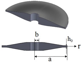
The thickness can be variable in the radial direction. Considering the variation of the thickness, the plane stress equilibrium equation in the radial direction is:
where is the radial stress, is the circumferential stress, is the thickness, is rotating speed of the plate and stands for the density. Considering the axisymmetric condition for the plate (), the Kirshoff strain-displacement relations become [33]:
where is the radial strain, is the tangential strain and is the shear strain in the plane of the plate and is radial displacement. The stress tensor has both the mechanical and thermal components due to existence of the thermal loading in the problem:
The elastic stiffness tensor relating the stresses to the strains in its most general form is shown below [13]:
The stress-strain relation can be written as the following [34]:
Considering the plane stress assumption in the plate, the stress components in out of plane direction are equal to zero:
Considering , the expressions for the thermal and mechanical strain components in out of plane direction is obtained. The remaining non-zero strain components are as the following:
where , and are respectively radial, tangential and out of plane strains due to thermal loading. Combining Eqs. (4), (5) and (6), the stresses in the rotating disk in a general form is found as:
where , , are the stiffness terms [13]:
In orthotropic materials, the elasticity moduli in radial and tangential direction and the Poisson ratios are related to each other by the following Equation [18, 35]:
where and are radial and tangential elasticity modulus, respectively. Considering the above Equation for and and the stress-strain elasticity tensor for transversely isotropic materials, the stiffness constants for the transversely isotropic material are [13]:
Substituting Eq. (8) into Eq. (1), the equilibrium equation is obtained in terms of radial displacement and the obtained equation should be solved considering the relevant boundary conditions. The following equations present the boundary equations of the problem.
Clamped-Free (C-F):
Free-Free (F-F):
3. Finite difference method
In the finite difference method, the disk is discretized along () radial stations. The method consists of developing an expression for the radial stress, employing three consecutive points [13]. At the end of the process, there are equations for the inner points and two known radial stress boundary equations for the inner and outer surface of the disk. The radial displacements are the unknown variables in the final matrix Eq. (14). In this paper, the stiffness terms (, , , ), thickness (), stresses () and displacement () are the functions of the radius (). Fig. 2 shows the numbering Scheme used in the method.
Fig. 2Numbering scheme in radial direction
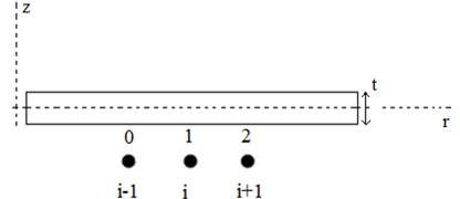
The radial stress can be estimated over intervals [1-2] and [0-1] from Eq. (5):
in which:
where 2, 1 and 1, 0. Similar expressions can be written for.
Integrating Eq. (1), and the second equation of Eq. (8) over intervals [1-2] and [0-1] and making use of the above expressions, we arrive at:
where:
Now, expressions can be developed for in intervals [1-2] and [0-1]. Omitting from Eq. (14) and Eq. (17) and substituting Eq. (19) in the resulted equation, the following expression for in terms of known quantities in the interval [1-2] is derived:
Also, omitting from Eq. (15) and Eq. (18) and substituting Eq. (20), the following relation for in the interval [0-1] is found:
Equating the right side of Eq. (22) and (23) and substituting , , , an equation with unknowns , , is obtained. The following equation leads to a system of () equations. The two remaining equations come from the discretization of the boundary conditions [13]:
In order to obtain the two remaining equations, the boundary conditions should be discretized. For the clamped boundary condition in inner or outer surfaces, the radial displacement in boundary surfaces should be zero and for the free boundary condition, the radial stress should be zero.
Applying the displacements of nodal points (), (), () and the displacements of nodal points 1, 2, 3 to Eq. (8), the discrete form of the boundary equations are as follows:
Clamped-Free (C-F):
Free-Free (F-F):
The discussed discretization leads to system of linear equations with the radial displacement () as the unknown variable. Once the radial displacement in nodal points is calculated, the radial stress can be found using Eq. (22) or Eq. (23).
4. FGM properties and thickness profile
For the numerical analyses, the disk is made of FG material that is pure ceramic in the inner surface and pure metal in the outer surface of the disk. The mechanical properties of the disk are assumed to vary by the following Equations in the radial direction:
where , and are the density of the ceramic (outer surface), radial elasticity modulus of the ceramic and thermal expansion in radial direction of the ceramic, respectively and , and are the corresponding material properties of metal and is FG graded index. Considering the orthotropy of the material, the mechanical properties in the radial and tangential directions are not equal and are related to each other by the following Equation [18, 35]:
The thickness of the disk is assumed to vary by a power-law function along the radial direction:
where is the thickness, is thickness in the outer radius and is thickness power index.
4.1. Thermal properties and thermal loading
The mechanical properties of ceramic and metal in the surfaces of the disc are considered temperature dependent. Temperature dependency of the material of the outer and inner surfaces is governed by Eq. (35) [36]:
where , , , and are tabulated in Table 1 [36] and can be elastic modulus, density and thermal expansion. The material properties of the ceramic and metal depend on the temperature by Eq. (35) and the disc is subjected to thermal load featuring a steady state temperature distribution along it’s radius expressed by Eq. (36):
where is temperature of the ceramic, is the temperature change from the inner surface to the outer surface and is temperature variation power index. Different temperature distributions are considered in the analyses by changing the parameter .
Table 1Temperature coefficients of material properties [36]
Material | Properties | |||||
SUS304 | (Pa) | 2.0104e+11 | 0 | 0.000308 | –6.53e-07 | 0 |
(K-1) | 1.23e-05 | 0 | 0.000809 | 0 | 0 | |
(kg/m3) | 8166 | 0 | 0 | 0 | 0 | |
Si3N4 | (Pa) | 3.4843e+11 | 0 | -0.00031 | 2.16e-07 | –8.95e-11 |
(K-1) | 5.87e-06 | 0 | 0.00091 | 0 | 0 | |
(kg/m3) | 2370 | 0 | 0 | 0 | 0 |
5. Validation
Prior to presentation of numerical results for thermo-elastic analysis of rotating FG orthotropic disk, the accuracy of the method should be verified. Two case studies are considered here for validation of the results. In Case (a), the stress analysis results for rotating FG isotropic disk are compared with those reported in [12]. The material properties of the disk are considered the same as the material and geometric properties of the disk in [12]. In Case (b), the results of the stress analysis of rotating FG polar orthotropic disk are compared with data in [18]. The material and geometric properties also in this case are considered the same as material and geometric properties considered in [18]. In both these cases, the thickness of the disk is taken to be uniform and the material gradation functions are power-law functions as the following. It should be mentioned that the material gradation functions for validation are different from the functions used in numerical analyses (Section 4):
where is graded index and is the outer radius. In case (a), the material is considered to be isotropic, therefore, and are equal to each other in case (a).
5.1. Case (a) validation
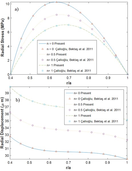
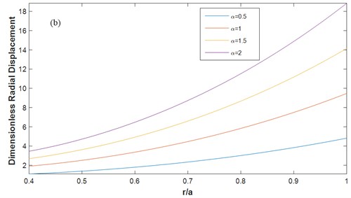
In this case, the disk is isotropic, and the radial and tangential elasticity modulus are equal. The disk is not under thermal loading and the material parameters are temperature independent. The material for the outer surface of the disc is aluminum alloy (7075-T6) with Young modulus of 72 GPa (in Eq. (37)) and the mass density of 2800 kg/m3 and the thickness of the disk is uniform. The Young modulus and density of the disc vary in the radial direction in accordance with Eq. (37). The rotating speed of the disk is 15000 rpm and the boundary conditions of the disk is Free-Free (F-F). The number of points in the grid in FD method for all the analyses is 100 points. The results of the displacement and stresses do not change considerably when the number of grid points increases to more than this number of points and convergence of the results are guaranteed. The radial stress and radial displacement of the disk are obtained using FD method and the results are compared with the results in [12]. Figs. 3 shows the comparison of the results for the radial stress and radial displacement. Fig. 3(a) shows the variation of radial stress () in the radial direction with (F-F) boundary conditions for 0, 0.5, 1. As it is observed from Fig. 3, there is a good agreement between the present results and those of [12], in which the solution is obtained by numerical and analytical methods.
Fig. 3Comparison of radial a) stress b) displacement variation
5.2. Case (b) validation
In this case, the dimensionless radial stress and displacement of the rotating FG polar orthotropic disc with uniform thickness and with F-F boundary conditions are obtained using FD method and the results are compared with the results reported in [18]. The material properties considered in this case are presented in Table 2 [18].
Table 2Material properties of the disk for comparison case (b)
An injection molded Nylon [37] (outer surface) | A glass-fiber/ Epoxy prepreg [26] (inner surface) | ||
Elasticity modulus (GPa) | 12 | 21.8 | |
20 | 26.95 | ||
Poisson ratio | 0.35 | 0.15 | |
Density (kg/m3) | 1600 | 2030 |
The dimensionless radial stress and radial displacement are defined as the following in this case:
where is the tangential elasticity modulus in the outer surface, is dimensionless radial stress and is dimensionless radial displacement. The dimensionless radial stress and displacement are obtained using FD method in this paper and the results are compared with the numerical and exact results [18] in Table 3. As one may observe, there is a very good agreement between the results which shows the accuracy of the present method.
Table 3Comparison of the stress and displacement in comparison case (b)
0.4 | 0.5 | 0.6 | 0.7 | 0.8 | 0.9 | 1.0 | |||
–1 | Exact [18] | 0 | 0.1780 | 0.2100 | 0.1852 | 0.1346 | 0.0709 | 0 | |
Numerical [18] | 0 | 0.1781 | 0.2099 | 0.1856 | 0.1349 | 0.0711 | 0 | ||
Present | 0 | 0.1778 | 0.2100 | 0.1852 | 0.1346 | 0.0709 | 0 | ||
Exact [18] | 0.2678 | 0.2553 | 0.2561 | 0.2622 | 0.2685 | 0.2708 | 0.2661 | ||
Numerical [18] | 0.2678 | 0.2554 | 0.2563 | 0.2625 | 0.2686 | 0.2709 | 0.2661 | ||
Present | 0.2679 | 0.2553 | 0.2562 | 0.2623 | 0.2685 | 0.2709 | 0.2661 | ||
0 | Exact [18] | 0 | 0.1066 | 0.1409 | 0.1369 | 0.1084 | 0.0617 | 0 | |
Numerical [18] | 0 | 0.1067 | 0.1409 | 0.1367 | 0.1086 | 0.0618 | 0 | ||
Present | 0 | 0.1064 | 0.1408 | 0.1369 | 0.1084 | 0.0616 | 0 | ||
Exact [18] | 0.3295 | 0.3141 | 0.3138 | 0.3186 | 0.3228 | 0.3228 | 0.3160 | ||
Numerical [18] | 0.3295 | 0.3142 | 0.3141 | 0.3189 | 0.3229 | 0.3229 | 0.3160 | ||
Present | 0.3297 | 0.3142 | 0.3139 | 0.3187 | 0.3229 | 0.3229 | 0.3160 | ||
1 | Exact [18] | 0 | 0.0619 | 0.0916 | 0.0984 | 0.0852 | 0.0525 | 0 | |
Numerical [18] | 0 | 0.0620 | 0.0917 | 0.0984 | 0.0853 | 0.0526 | 0 | ||
Present | 0 | 0.0618 | 0.0916 | 0.0984 | 0.0852 | 0.0525 | 0 | ||
Exact [18] | 0.4015 | 0.3824 | 0.3802 | 0.3827 | 0.3840 | 0.3811 | 0.3718 | ||
Numerical [18] | 0.4015 | 0.3826 | 0.3805 | 0.3828 | 0.3841 | 0.3812 | 0.3718 | ||
Present | 0.4016 | 0.3825 | 0.3803 | 0.3827 | 0.3841 | 0.3812 | 0.3719 | ||
2 | Exact [18] | 0 | 0.0347 | 0.0577 | 0.0687 | 0.0654 | 0.0440 | 0 | |
Numerical [18] | 0 | 0.0348 | 0.0578 | 0.0687 | 0.0654 | 0.0441 | 0 | ||
Present | 0 | 0.0347 | 0.0577 | 0.0687 | 0.0653 | 0.0440 | 0 | ||
Exact [18] | 0.4794 | 0.4562 | 0.4512 | 0.4504 | 0.4483 | 0.4421 | 0.4303 | ||
Numerical [18] | 0.4794 | 0.4561 | 0.4514 | 0.4506 | 0.4484 | 0.4422 | 0.4302 | ||
Present | 0.4795 | 0.4563 | 0.4513 | 0.4505 | 0.4483 | 0.4421 | 0.4303 | ||
6. Numerical results and discussion
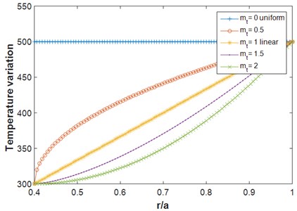
For the numerical analysis, Eqs. (29)-(31) are used for mechanical properties variation along the radius of the disk and Eqs. (32)-(33) are used for orthotropic properties of the disk. Eq. (34) is also used for considering the thickness variation of the disk. Fig. 4 shows temperature distributions along the radius with different thermal parameters based on Eq. (36). It should be mentioned that the inner surface is pure ceramic and outer surface is pure metal.
Fig. 4Temperature variation along the radius
The dimensionless radial stress and radial displacement are defined:
where is density of the metal (outer surface) and is tangential elasticity modulus of the metal. The dimensionless radial stress and displacement are obtained using the FD method and the effects of different thermo-mechanical properties on the stress and displacement are evaluated.
The rotating speed of the disk is 1000 rad/s and the inner/outer radius ratio is 0.4 in all the numerical analyses. Fig. 5 shows the variation of dimensionless radial stress and radial displacement (Eq. (40) and (41)) for the rotating polar orthotropic FG disk with variable thickness for different values of temperature variation between the inner and outer surfaces ( in Eq. (36)). The boundary conditions are C-F, the thickness variation and the temperature variation in the radial direction are linear (, ). Fig 6 shows the same figure but for F-F boundary conditions. The temperature of ceramic in the inner surface is 300 K and the metal temperature depends on the value of temperature change between the inner and outer surfaces. As shown in Figs. 5-6, increasing the temperature variation, the radial stress and displacement start to grow. Also, it can be observed from Fig. 6 that at higher temperature variations in F-F disk, the location of maximum radial stress in the disk shifts toward the inner surface. It is concluded that the variation of the temperature along the radius can cause an increase in the radial stress and displacement in both the C-F and F-F boundary conditions.
Fig. 7 shows the radial stress and displacement of the rotating orthotropic FG disk for different temperature variations along the radius with C-F and F-F boundary conditions. The temperature difference between the inner and outer surfaces are 200 K where the different temperature variations in radial direction are plotted in Fig. 4. As shown in Fig. 7, increasing the temperature variation power index () in rotating C-F disk, the radial stress and displacement decrease. The stress in the inner surface and the displacement in the outer surface for larger values of are lower. It is also observed in Fig. 7 that the radial stress increases when the temperature is varied along the radius () compared to when the temperature is held constant in the radial direction (). In contrary, the radial displacement in F-F rotating disk decrease when the temperature is varied in the radial direction and by increasing , the radial displacement decrease.
Fig. 5Dimensionless radial a) stress b) displacement for different values of the temperature variation C-F (α= 0.5, β= 0.5, n=1, m1= 1, mt= 1)
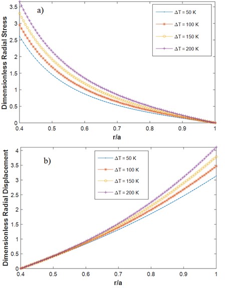
Fig. 6Dimensionless radial a) stress b) displacement for different values of temperature variation F-F (m1= 1, mt= 1, α= 0.5, β= 0.5, n= 1)
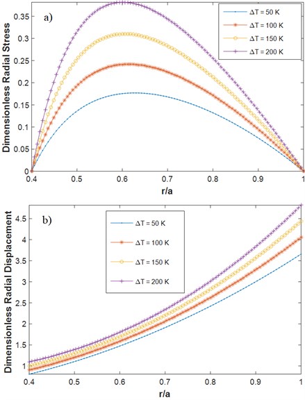
Fig. 7Dimensionless radial: a) stress (C-F), b) displacement (C-F), c) stress (F-F) d) displacement (F-F) for different temperature variation profiles (different mt’s according to Fig. 5) in radial direction C-F (m1= 1, ΔT= 200 K, α= 0.5, β= 1, n= 1)
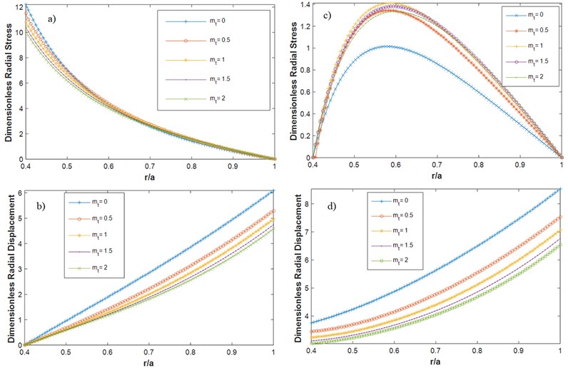
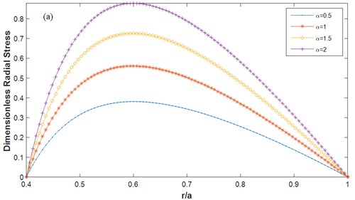
Fig. 9Dimensionless radial a) stress b) displacement for different α F-F (m1= 1, ΔT= 200 K, β= 0.5, mt= 1, n= 1)
The effect of FG index on the radial stress and displacement of the rotating FG orthotropic uniform disk under thermal loading with F-F boundary conditions can be observed in Fig. 8. It is shown that the radial stress and radial displacement in the rotating FG disk is decreased by the increase in FG index. It is also observed that the rate of variation of the radial displacement from the inner surface to the outer surface decrease significantly by increasing the FG index.
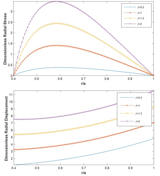
In order to investigate the effect of orthotropy on the stress and displacement of the rotating FG disk, the influence of parameters and on the results is evaluated. The material with 1 denotes an isotropic material. Fig. 9 shows the radial stress and displacement of the rotating FG orthotropic uniform disk under thermal loading with F-F boundary conditions for different values of orthotropic parameter . The parameter is equal to 0.5, and the temperature variation in the disk is linear (). As observed from Fig. 9, for lower values of parameter , the radial stress and displacement increase significantly. It should be mentioned that the same trend is observed for the disk with C-F boundary conditions, but the relevant results are not presented here for the sake of briefness. Fig. 10 shows the results similar to the results of Fig. 9, but for different values of orthotropic parameter . The same trend is observed for the variation of . It should be again mentioned that the same trend is observed for the C-F boundary condition but its results are not presented for the brevity.
Fig. 10Dimensionless radial a) stress b) displacement for different β F-F (m1= 1, ΔT= 200 K, α= 0.5, mt=1, n= 1)
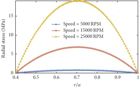
The effects of rotating speed on the stress in the rotating disk is also presented in Fig. 11. In Fig. 11, the variation of radial stress of a rotating FG disk for different values of rotating speed is shown. As it is expected, by increasing the rotating speed of the rotating FG disk, the stress in the disk is increased. It should be mentioned that in this figure, the material of the disk is considered isotropic but the result for orthotropic material was also obtained and the same trend was concluded.
Fig. 11The radial stress versus radius with different rotating speeds (m1= –1, ΔT= 0, α=β= 1, mt= 1, n= 1)
7. Conclusions
In this paper, the numerical finite difference method was employed to analyze the thermo-elastic stress and deformation of rotating FG polar orthotropic disk with variable thickness. The material of the disk was considered temperature dependent and different temperature variations along the radius of the disk were considered for the analyses. Radial stress and radial displacement of the rotating disk with C-F and F-F boundary conditions were calculated using the FD method. The effects of various mechanical properties on the radial stress and radial deflection were investigated. The following results are the summary of the most important results of the paper.
1) It was concluded that the variation of the temperature along the radius can cause the increase in radial stress and displacement in rotating FG orthotropic disk.
2) The radial stress increases when the temperature is varied along the radius () compared to when the temperature is kept constant in the radial direction ().
3) The rate of variation of the radial displacement from the inner surface to the outer surface decrease significantly through increasing the FG index.
4) The orthotropy of the material of the disk has a significant effect on the displacement and stress distribution of the disk. It is concluded that the desired stress and displacement in the rotating FG disk can be obtained with manufacturing orthotropic disks.
References
-
Ruys A., Sun D. Functionally graded materials (FGM) and their production methods. 2002, http://www.azom.com/article.aspx.
-
Mahamood R. M., et al. Functionally graded material: an overview. Proceedings of the World Congress on Engineering, 2012.
-
Bayat M., et al. Mechanical and thermal stresses in a functionally graded rotating disk with variable thickness due to radially symmetry loads. International Journal of Pressure Vessels and Piping, Vol. 86, Issue 6, 2009, p. 357-372.
-
Jalali M. H., Zargar O., Baghani M. Size-dependent vibration analysis of FG microbeams in thermal environment based on modified couple stress theory. Iranian Journal of Science and Technology, Transactions of Mechanical Engineering, Vol. 43, 2019, p. 761-771.
-
Nemirovskii Y. V., et al. Rational profiling of reinforced rotating disks. Mechanics of Composite Materials, Vol. 38, 2002, p. 1-16.
-
Asghari M., et al. A three-dimensional elasticity solution for functionally graded rotating disks. Composite Structures, Vol. 92, 2010, p. 1092-1099.
-
Bayat M., Sahari B. B., Hamouda A. M. S., Mahdi E. Analysis of functionally graded rotating disks with variable thickness. Mechanics Research Communications, Vol. 35, 2008, p. 283-309.
-
Zafarmand H., et al. Analysis of two-dimensional functionally graded rotating thick disks with variable thickness. Acta Meccanica, Vol. 225, Issue 2, 2014, p. 453-464.
-
Peng Xu Long, et al. Effects of gradient on stress distribution in rotating functionally graded solid disks. Journal of Mechanical Science and Technology, Vol. 26, 2012, p. 1483-1492.
-
Eraslan A. N. Elastic-plastic deformations of rotating variable thickness annular disks with free, pressurized and radially constrained boundary conditions. International Journal of Mechanical Sciences, Vol. 45, Issue 4, 2003, p. 643-667.
-
Çallıoğlu H., Demir E., et al. Elastic-plastic stress analysis of rotating functionally graded discs. Thin-Walled Structures, Vol. 94, 2015, p. 38-44.
-
Callioglu H., et al. Stress analysis of functionally graded rotating discs: analytical and numerical solutions. Acta Mechanica Sinica, Vol. 27, 2011, p. 950-955.
-
Gutzwiller D. Automated Design, Analysis, and Optimization of Turbomachinery Disks, in Aerospace Engineering. University of Cincinnati, 2009.
-
Gutzwiller D. P., et al. Rapid low fidelity turbomachinery disk optimization. Advances in Engineering Software, Vol. 41, 2010, p. 779-791.
-
Shahriari B., Jalali M. H., Karamooz Ravari M. Vibration analysis of a rotating variable thickness bladed disk for aircraft gas turbine engine using generalized differential quadrature method. Proceedings of the Institution of Mechanical Engineers, Part G: Journal of Aerospace Engineering, Vol. 231, Issue 14, 2017, p. 2739-2749.
-
Nie G. J., et al. Stress analysis and material tailoring in isotropic linear thermoelastic incompressible functionally graded rotating disks of variable thickness. Composite Structures, Vol. 92, 2010, p. 720-729.
-
Tutuncu N. Effect of anisotropy on inertio-elastic instability of rotating disks. International Journal of Solids and Structures, Vol. 37, 2000, p. 7609-7616.
-
Peng X. L., et al. Elastic analysis of rotating functionally graded polar orthotropic disks. International Journal of Mechanical Sciences, Vol. 60, 2012, p. 84-91.
-
Callıoglu H., Tarakcılar A. Elastic–plastic stress analysis of an orthotropic rotating disc. International Journal of Mechanical Sciences, Vol. 48, 2006, p. 985-990.
-
Nie G. J., Batra R. C., et al. Material tailoring for orthotropic elastic rotating disks. Composites Science and Technology, Vol. 71, 2011, p. 406-414.
-
Jalali M. H., et al. Free vibration analysis of rotating functionally graded annular disc of variable thickness using generalized differential quadrature method. Scientia Iranica, Vol. 25, Issue 2, 2018, p. 728-740.
-
Jalali M. H., et al. Evaluation of dynamic behavior of a rotor-bearing system in operating conditions. World Academy of Science, Engineering and Technology, International Journal of Mechanical, Aerospace, Industrial, Mechatronic and Manufacturing Engineering, Vol. 8, Issue 10, 2014, p. 1675-1679.
-
Carrera E., Filippi M., Kouchakzadeh M. A., et al. 3D thermoelastic analysis of rotating disks having arbitrary profile based on a variable kinematic 1D finite element method. Journal of Thermal Stresses, Vol. 39, 2016, p. 1572-1587.
-
Kouchakzadeh M. A., et al. Analytical solution of classic coupled thermoelasticity problem in a rotating disk. Journal of Thermal Stresses, Vol. 38, 2015, p. 1269-1291.
-
Entezari A., et al. Analytical solution of generalized coupled thermoelasticity problem in a rotating disk subjected to thermal and mechanical shock loads. Journal of Thermal Stresses, Vol. 39, 2016, p. 1588-1609.
-
Callioglu H. Stress analysis of an orthotropic rotating disc under thermal loading. Journal of Reinforced Plastic and Composites, Vol. 23, 2004, p. 1859-1867.
-
Kursun A., Tetik T., et al. Stress analysis of functionally graded disc under thermal and mechanical loads. Procedia Engineering, Vol. 10, 2011, p. 2949-2954.
-
Hassani A., Mahdavi E., Alashti R. A., Farrahi G., et al. Thermo-mechanical analysis of rotating disks with non-uniform thickness and material properties. International Journal of Pressure Vessels and Piping, Vol. 98, 2012, p. 95-101.
-
Dai T., et al. Thermo-elastic analysis of a functionally graded rotating hollow circular disk with variable thickness and angular speed. Applied Mathematical Modelling, Vol. 40, 2016, p. 7689-7707.
-
Hosseini Kordkheili S. A., et al. Thermoelastic analysis of a functionally graded rotating disk. Composite Structures, Vol. 79, 2007, p. 508-516.
-
Azadi M. D. M. Temperature and thickness effects on thermal and mechanical stresses of rotating FG-disks. Journal of Mechanical Science and Technology, Vol. 25, 2011, p. 827-836.
-
Gong J. F., Xuan L. K., et al. Thermoelastic analysis of three-dimensional functionally graded rotating disks based on finite volume method. Proceedings of the Institution of Mechanical Engineers: Journal of Mechanical Engineering Science, Vol. 228, Issue 4, 2013, p. 583-598.
-
Jalali M. H., Shahriari B. Elastic stress analysis of rotating functionally graded annular disk of variable thickness using finite difference method. Mathematical Problems in Engineering, Vol. 2018, 2018, p. 1871674.
-
Ding H., Zhang L., et al. Elasticity of Transversely Isotropic Materials. Springer, Netherlands, 2006.
-
Shi Rong Li, Lian Sheng Ma, et al. Vibration of thermally post-buckled orthotropic circular plates. Journal of Thermal Stresses, Vol. 30, 2007, p. 43-57.
-
Reddy J. N., et al. Thermo-mechanical analysis of functionally graded cylinders and plates. Journal of Thermal Stresses, Vol. 21, 1998, p. 593-626.
-
Çallıoğlu H. Thermal stress analysis of curvilinearly orthotropic rotating disks. Journal of Thermoplastic Composite materials, Vol. 20, 2007, p. 357-369.
About this article

