Abstract
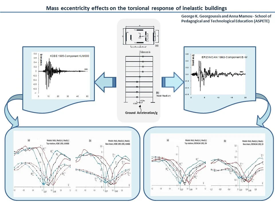
This paper investigates the role of accidental mass eccentricities on the inelastic torsional behaviour of multi-storey asymmetric buildings with a mixed type lateral load resisting system subjected to the Erzincan-1992 and Kobe-1995 ground motions. The numerical modelling results show that the effects of spatial variations of mass eccentricities are lower and smoother in the inelastic rather than the elastic state of deformation, but both the elastic and inelastic torsional response is pointing to the same optimum location of the key element for which the torsional response of the structure is minimized.
Highlights
- The effects of spatial variations of mass eccentricities are not significantly different in the elastic and inelastic state of deformation
- Both the elastic and inelastic torsional response are pointing to the same optimum location of the key lateral load resisting element, for which the torsional response of the structure is minimized
- The inelastic torsional response was generally smoother than the elastic response
- The inelastic results are indicating an extended range of possible locations of the key element, for which insignificant changes in the torsional response of the structure occurred
1. Introduction
The term “accidental mass eccentricity” originates from many uncertainties such as non-uniform mass and stiffness distributions, and possible rotational effects of the ground motion. Stiffness uncertainties may increase the structural deformations, to 5 and 10 per cent, for reinforced concrete and steel buildings respectively [1]. Spatial variations of mass eccentricities may significantly increase the dynamic structural response of buildings as compared to the results obtained from a static structural analysis [2]. Recent research studies on inelastic systems, based on the provisions of current design codes, demonstrated that the benefits of the inelastic analyses may be small, compared to designs where the accidental eccentricity was not taken into account [3-7]. It was therefore suggested that accidental design eccentricities may not be taken into account or perhaps replaced by simpler design guidelines. The definition a vertical axis in multistory buildings for which any in-plane applied lateral loading, causes minimum torsion response is an old and open issue. Defining the center of rigidity (CR) in one-story systems may be a relatively straightforward procedure, as it is essentially the center of lateral stiffness, but its definition, in the various floors of a multistory building is not an equally straightforward task. The “rigidity centers” (CRs) were proposed as a reference axis for structural applications [8], but, except for the case of proportionate structures, these points are load dependent and their space distribution is highly irregular, even in uniform structures composed of different types of bents.
Acknowledging the deficiencies of using the CRs as a basis for assessing the torsional response of building structures, a number of researches proposed alternative methods to define the reference points for implementing the torsional code provisions [9-12]. The main objective of these studies was to determine the location of a vertical axis for which any in-plane applied lateral loading, the torsional distortion on the structure would be minimized. This axis constitutes an optimum torsion axis (OTA) and can be either determined using the approximate method of the continuous medium [13, 14], which defines the OTA as the vertical axis passing through the center of rigidity (m-CR) of an equivalent (modal) single story system, or alternatively, using the discrete element approach (stiffness method), which is familiar to practicing engineers [15]. When all the centers of masses on the various floors lie on the optimum torsion axis, the seismic response of structural buildings is essentially translational and such a structural configuration may be easily obtained with a suitable arrangement of the key lateral load resisting bent (key structural element).
In a recent paper, which investigated the role of accidental mass eccentricities on the elastic torsional response of buildings, it was shown that (i) a structural configuration of practically translational response may also be attained by a suitable relocation of the key element and (ii) by reversing the spatial distribution of floor masses, the same response is achieved when the key structural element is shifted to a symmetrical location with respect to its nominal location, when no mass eccentricities are accounted for [16]. This paper extends the analysis into the inelastic region by investigating the role of accidental mass eccentricities on the inelastic torsional response of 9-storey asymmetric buildings.
2. Numerical example
The plan configuration of the investigated 9-storey concrete building is presented in Fig. 1. It consists of an orthogonal floor plan of 18×12 m and the total mass per floor is 154 kNs2/m(assuming a total gravity load density of 7 kN/m2). The story height is 3.5 m and the concrete modulus of elasticity is assumed equal to 20x106 kN/m2, typical for concrete structures. The lateral resistance along the -direction is provided by four resisting elements: a flexural shear wall, W, with a cross section of 35×350 cm, a coupled wall bent, CW, composed of two walls of 35×270 cm at a distance of 5 m, connected by lintel beams 30×80 cm at the floor levels and, also, by two moment resisting frames, FR, composed by two columns of 70×70 cm, 6 meters apart, connected by beams of a cross section 40×70 cm. The lateral resistance along the -axis is provided by a pair of flexural shear walls, Wx, of a cross section 35×450 cm. The strength distribution of the various bents of the investigated building was based on static considerations about the response of its symmetrical counterpart, where all the floors are restrained against any rotation. The non-linear properties of the structural elements were assigned using the ultimate capacity design assumption (strong columns-weak beams) and the strength capacities of the various members were evaluated by means of a static (linear) analysis under an external lateral loading with floor forces having the shape of the ‘inverted triangle’ and summing to a base (design) shear, , equal to 20 % of the total weight.
Fig. 1a) Plan configuration of example structure (all dimensions in meters), b) the mass eccentricity model: MassEc(+)
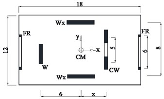
a)
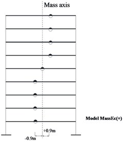
b)
For practical reasons the reinforcement detailing was the same for all beams and at the locations of plastic hinges the moment-rotation relationship was assumed to be bilinear, with a post-yielding stiffness ratio equal to 1 % and the maximum plastic rotation capacity was 0.015 rads at the ultimate bending moment.
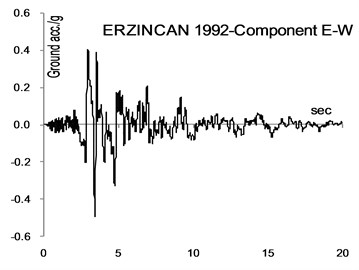
Three different models of the example building of Fig. 1(a) were analyzed using the SAP structural analysis program for the Kobe 1995 (component KJM000) and Erzincan 1992 (component EW) ground excitation (Figs. 2 and 3) scaled to PGA = 0.5 g. In the first model (labelled NoEc) all the centres of floor masses are aligned along the vertical line passing through the centroids of the floor plans (nominal location of all floor masses). In the second model (MassEc(+)) the centres of all floor masses are shifted along the -direction to the locations shown in Fig. 1(b). This is a model with a typical spatial distribution of accidental mass eccentricities. In all three cases, the mass polar moment of inertia was equal to that of the system when no mass eccentricities were taken into account. In the third model (MassEc(-)) the mass eccentricities shown in Fig. 1(b) are reversed.
Fig. 2Ground motions considered
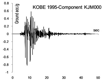
Fig. 3Ground motions considered
3. Discussion of results
The time history analysis was performed using the numerical implicit Wilson- time integration method, with the parameter taken as 1.4, while the damping matrix was assumed to be stiffness and mass proportional (the damping ratio was taken equal to 5 % for the first and third coupled periods of vibration). In order to assess the optimum location of the CW bent, for which the torsional response of the structure was minimized, the numerical analysis was performed for any possible location, , of the CW bent between –7.5 m to +7.5 m, along the -axis. In normalized coordinates: (where is the radius of gyration of the floor mass about CM) the location of CW is varying from –1.2 to 1.2.
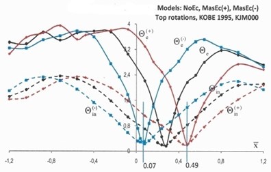
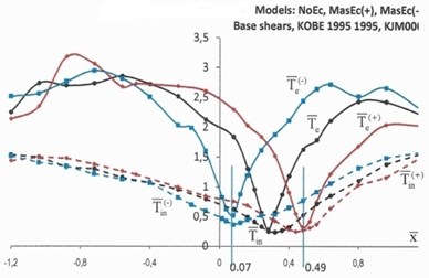
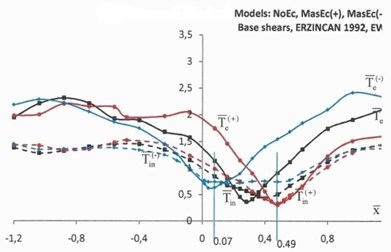
The elastic and inelastic response of the structure in terms of the top rotations, , and normalized base torques is illustrated in Figs. 4 and 5. The elastic response in Figs. 4 and 5 is denoted by solid lines, while the inelastic response is denoted by dotted lines. The black lines denote the response of NoEc models, the red lines show the response of the models with mass eccentricities distribution as shown in Fig. 1(b) (MassEc(+)), while the blue lines show the response of the models with reversed mass eccentricities (MassEc(-)).
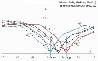
The inverted peak of the elastic response of the structure in terms of top rotations and base torques indicates an optimum location of the coupled wall bent CW for which the torsional response of the structure is minimized. This is more pronounced for the structural response under the Kobe ground excitation (solid lines Fig. 4) and to a lesser extent for the structural response under the Erzincan ground excitation (solid lines Fig. 5), where the curves are relatively smoother. The elastic response of the MassEc(+) (red solid curves) and reversed mass eccentricity model MassEc(-) (blue solid curves) are pointing to almost symmetrical locations, with respect to the nominal location of the CW bent in the NoEc model (black solid curves). A small shift of the coupled wall bent CW from its optimum location results in large torsional distortions, which reduce as the CW bent moves further away from the optimum location. The elastic response under the Kobe ground excitation (Fig. 4) has a rather steep dip in the vicinity of the optimum location of coupled wall bent CW, but the response becomes smoother and even flattens out for larger shifts of this bent. This is less pronounced for the elastic response of the Erzincan ground excitation (Fig. 5). Note here that according to analysis outlined in [16] the optimum locations, in terms of the normalized coordinate, , of the key element (CW bent) in the mass eccentric systems of MassEc(+) and MassEc(-) are respectively equal to 0.49 and 0.07 and these locations are shown in Figs. 4 and 5 by separate lines. For model NoEc, the corresponding optimal location of CW bent is found to be equal to 0.28.
Fig. 4Top rotations, Θ (×10-2 rads), and normalized base torques, T-, of models NoEc (black lines), MassEc(+) (red lines) and MassEc(-) (blue lines) responding as elastic (labeled by the subscript “e”) and inelastic (labeled by the subscript “in”) systems under the ground excitation of Kobe 1995
a)
b)
Fig. 5Top rotations, Θ (×10-2 rads), and normalized base torques, T-, of models NoEc (black lines), MassEc(+) (red lines) and MassEc(-) (blue lines) responding as elastic (labeled by the subscript “e”) and inelastic (labeled by the subscript “in”) systems under the ground excitation of Erzincan 1992
a)
b)
The inelastic response of the investigated models in terms of both top rotations and base torques, is generally smoother than the elastic torsional response, which confirms the results on inelastic asymmetric building, which showed that structural systems continue to deform in a translational mode after yielding had occurred [18, 19]. Both elastic and inelastic results generally point to the same optimum location of the coupled wall bent CW for which the torsional response of the structure is minimized, extending the observations made on the elastic and inelastic response of systems with no mass eccentricities [20]. At the locations of the coupled wall bent CW for which the torsional response of the structure is minimized, the elastic response of the structure is essentially translational and its subsequent, similar, inelastic response may be interpreted as follows: when the elastic response is translational, the seismic forces acting on a medium or low height structures are essentially proportional to the first translational mode of vibration. Therefore, a strength assignment obtained from a planar static analysis under a set of lateral loads simulating the aforementioned mode of vibration represents a system for which all potential plastic hinges are almost instantly formed at the critical cross sections.
Based on the results of Figs. 4 and 5 it may be concluded that the variation of the inelastic response in terms of base torques, in the range of normalized coordinates, , of CW from 0.07 to 0.49 is insignificant and practically any location of CW within this interval may potentially be an optimum location of the CW bent. In other words, when a building is pushed beyond its elastic limits under a strong ground motion, a structural design based on the nominal locations of the floor masses may adequately predict the optimum location of the key CW bent.
4. Conclusions
This paper investigates the role of accidental mass eccentricities on the inelastic torsional response of 9-storey asymmetric buildings, subjected to the Kobe 1995 (component KJM000) and Erzincan 1992 (component EW) ground excitations. The numerical modelling results show that spatial variations of mass eccentricities did not significantly differentiate the trend of the elastic from the inelastic response of the structure, with both the elastic and inelastic torsional response pointing to the same optimum location of the coupled wall bent CW for which the torsional response of the structure was minimized. The inelastic torsional response of the investigated buildings was generally smoother than the elastic response, with the inelastic results indicating an extended range of possible locations of the couple wall bent CW, for which minor changes in the torsional response of the structure occurred.
References
-
De-La-Llera J. C., Chopra A. K. Accidental torsion in buildings due to stiffness uncertainties. Earthquake Engineering and Structural Dynamics, Vol. 23, 1994, p. 117-136.
-
De-La-Llera J. C., Chopra A. K. Estimation of accidental torsion effects for seismic design of buildings. Journal of Structural Engineering, Vol. 121, Issue 1, 1995, p. 102-114.
-
Stathopoulos K. G., Anagnostopoulos S. A. Accidental design eccentricity: Is it important for the inelastic response of buildings to strong earthquakes? Soil Dynamics and Earthquake Engineering, Vol. 30, Issue 9, 2010, p. 782-797.
-
Anagnostopoulos S. A., Kyrkos M. T., Stathopoulos K. G. Earthquake induced torsion in buildings: critical review and state of the art. Earthquakes and Structures, Vol. 8, Issue 2, 2015, p. 305-377.Anagnostopoulos S. A., Kyrkos M. T., Papalymperi A., Plevri E. Should accidental eccentricity be eliminated from Eurocode 8? Earthquakes and Structures, Vol. 8, Issue 2, 2015, p. 463-484.
-
Bosco M., Ferrara G. A. F., Ghersi A., Marino E. M., Rossi P. P. Seismic assessment of existing R.C. framed structures with in-plan irregularity by nonlinear static methods. Earthquakes and Structures, Vol. 8, Issue 2, 2015, p. 401-422.
-
Bosco M., Ghersi A., Marino E. M., Rossi P. P. Generalized corrective eccentricities for nonlinear static analysis of buildings with framed or braced structure. Bulletin of Earthquake Engineering, Vol. 15, Issue 11, 2017, p. 4887-4913.
-
Cheung V.-W.-T., Tso W. K. Eccentricity in irregular multi-story building. Canadian Journal of Civil Engineering, Vol. 13, 1986, p. 46-52.
-
Makarios T., Anastassiadis K. Real and fictitious elastic axis of multi-storey buildings: theory. The Structural Design of Tall and Special Buildings, Vol. 7, Issue 1, 1998, p. 33-45.
-
Makarios T., Anastassiadis K. Real and fictitious elastic axis of multi-storey buildings: applications. The Structural Design of Tall and Special Buildings, Vol. 7, Issue 1, 1998, p. 57-71.
-
Marino E. M., Rossi P. P. Exact evaluation of the location of the optimum torsion axis. The Structural Design of Tall and Special Buildings, Vol. 13, 2004, p. 277-290.
-
Basu D., Jain S. K. Alternative method to locate center of rigidity in asymmetric buildings. Earthquake Engineering and Structural Dynamics, Vol. 36, 2007, p. 965-973.
-
Georgoussis G. K. Modal Rigidity Center: its use for assessing elastic torsion in asymmetric buildings. Earthquakes and Structures, Vol. 1, Issue 2, 2010, p. 163-175.
-
Georgoussis G. K. An approach for minimum rotational response of medium-rise asymmetric structures under seismic excitations. Advances in Structural Engineering, Vol. 19, Issue 3, 2016, p. 420-436.
-
Georgoussis G. K. Locating optimum torsion axis in asymmetric buildings subjected to seismic excitation. Proceedings of the Institution of Civil Engineers – Structures and Buildings, Vol. 171, Issue 9, 2018, p. 688-695.
-
Georgoussis G. K., Mamou A. The effect of mass eccentricity on the torsional response of building structures. Structural Engineering and Mechanics, Vol. 67, Issue 6, 2018, p. 671-682.
-
Georgoussis G. K., Mamou A. The effect of mass eccentricity on the torsional response of inelastic buildings – a case study. Proceedings of the Institution of Civil Engineers Structures and Buildings, under review, 2019, (in press).
-
Kan C. L., Chopra A. K. Torsional coupling and earthquake response of simple elastic and inelastic systems. Journal of the Structural Division, Vol. 107, Issue 8, 1981, p. 1569-1588.
-
Ghersi A., Rossi P. P. Influence of bi-directional ground motions on the inelastic response of one-story in-plan irregular systems. Engineering Structures, Vol. 23, 2001, p. 579-591.
-
Georgoussis G. K. Minimizing the torsional response of inelastic multistory buildings with simple eccentricity. Canadian Journal of Civil Engineering, Vol. 42, Issue 11, 2015, p. 966-969.
Cited by
About this article

This work has been (co-)financed by the Greek School of Pedagogical and Technological Education through the operational program “Research strengthening in ASPETE” – Project SSKK (80144).
