Abstract
A backfilling hydraulic support with six pillars used for working face roof support and goaf backfilling in coal mine is designed, and the structure and working principle of the backfilling hydraulic support are described. In order to improve the working stability of backfilling hydraulic support, the differential equations of motion and the state space model of backfilling hydraulic support are established based on Lagrange method and space coordinate system. According to the support structure and related parameters, the differential equation of motion of the system is solved by MATLAB. The influence law of disturbance frequency and amplitude on the top beam vertical vibration, roll and pitch vibration is obtained. The results show that the vertical vibration and roll vibration of the top beam are more severe in the low frequency range. And the degree of vibration gradually decreases as the disturbance frequency increases. As the disturbance amplitude increases, the vibration of the top beam is more severe. The vibration of the backfilling hydraulic support and the deformation distribution nephogram of the top beam are obtained by the finite element analysis, the validity of the dynamic model is verified by finite element simulation. The results provide the basis for the optimization design and the stability evaluation of backfilling hydraulic support.
1. Introduction
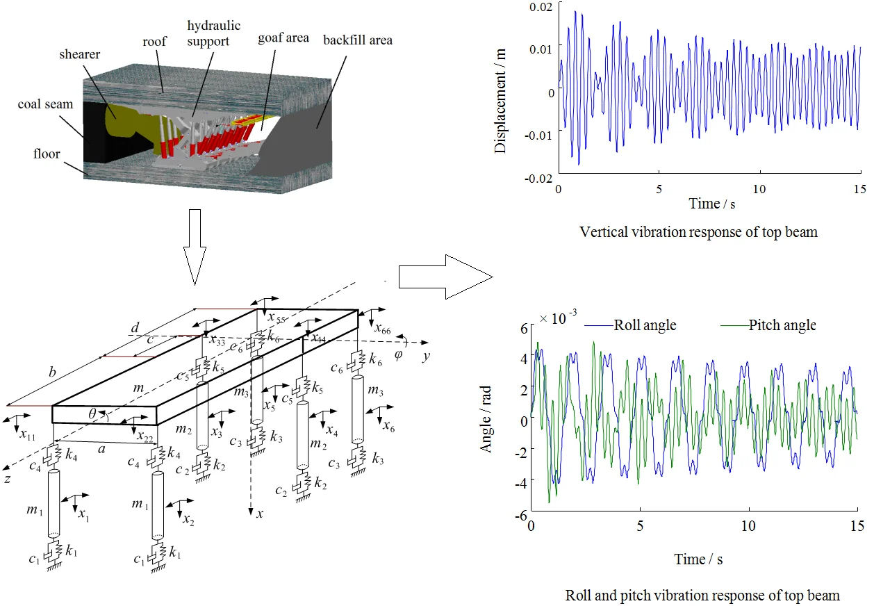
In order to realize the safe production of coal mine and the green mining of coal mine, people pay more and more attention to the backfilling technology of fully mechanized mining [1, 2]. As one of the important equipment in backfilling mining technology, backfilling hydraulic support can play the role of traditional hydraulic support in fixing support, isolating mining area and goaf. The conveying mechanism and tamping mechanism can be arranged on the backfilling hydraulic support to transport and tamp the filling materials, which can improve the stress state of overlying strata and restrain the roof subsidence [3]. The application of backfilling support in fully mechanized face is shown in Fig. 1.
The performance of backfilling the hydraulic support has an important impact on the normal operation of the relevant equipment, which is related to the safe production of the entire mine. Therefore, many experts and scholars have studied the backfilling of hydraulic supports. Zhou Yuejin analyzed the force of the top beam of the hydraulic support, the movement process of the main components of the backfilling hydraulic support was simulated, and the corresponding motion characteristic curve was obtained [4]. Xu Junming analyzed the structure of the backfilling hydraulic support, established a mechanical relationship model between the backfilling hydraulic support and the surrounding rock [5, 6]. Through the tilting and sliding experiments of hydraulic support on the test bench, Gongpeilin concluded that the mining height, inclination angle, height of center of gravity of the support have important influence on the tilting and sliding of the support [7, 8]. By analyzing the interaction between the hydraulic support and the direct jack, Qi Fangkun established the force model of the four-pillar backfilling support and calculates the working resistance of the pillar and the jack [9]. The above research mainly focuses on the analysis of the structural stress of the backfilling hydraulic support and its relationship with the surrounding rock, and there are few studies on dynamic models and dynamic characteristics of backfilling hydraulic support.
The structure and working principle of backfilling hydraulic support with six pillars are analyzed in this paper. The multi-freedom vibration model and the state space model of the backfilling hydraulic support are established. The differential equations are solved by numerical integration method, and the dynamic response of the backfilling hydraulic support under different excitations is obtained.
Fig. 1Application of backfilling support in working face
2. The structure of backfilling hydraulic support with six pillars
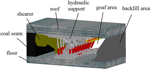
The backfilling hydraulic support with six pillars is a special hydraulic support that integrates the functions of support and backfilling [10, 11].It is mainly composed of telescopic beam, top beam, pillar four-bar linkage mechanism, tamping institution, filling scraper conveyor, support base, etc. The structure and three-dimensional model of the backfilling hydraulic support are shown in Fig. 2.
Fig. 2The Three-dimensional model of backfilling hydraulic support with six pillars
The top beam is supported by the front and center pillars and is balanced by a four-bar linkage. The rear top beam and the top beam are hinged to each other, the beam bears the pressure of the roof through the support of pillars and controls the roof subsidence before backfilling. A backfilling conveyor is suspended on the rear top beam to realize backfilling in goaf. The tamping institution is articulated with the support base, the pendulum beam jack controls the tamping mechanism to swing up and down, the tamping jack controls the tamping beam to expand and contract, and the filling material is tamped through the shovel. In order to improve the support strength of the rear top beam, the hydraulic support adds two rear pillars to the back of the support, and the support resistance of the top beam increases, which can reduce the roof subsidence and improve the backfilling effect.
3. Establishment of dynamic model
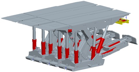
The dynamic model of the backfilling hydraulic support with six pillars is shown in Fig. 3. , , , , , are damping coefficient of the backfilling hydraulic support; , , , , , are stiffness coefficient of are damping coefficient of the backfilling hydraulic support; , , , are the total mass of the top beam and the concentrated mass of the top beam to the pillar, kg; , are pitch moment and roll moment of inertia, kg·m2; , , and are the width of the top beam and the center of the top beam to the distance between the front, middle and rear pillars, mm; are vertical displacement of top beam centroid, mm; is vertical displacement of concentrated mass under left front beam, mm; is vertical displacement of concentrated mass under right front girder, mm; is vertical displacement of concentrated mass under left middle front beam, mm; is vertical mass displacement under the right middle front beam,mm; is vertical mass displacement under left rear beam ,mm; is vertical mass displacement under right rear girder, mm; and are side slope angle and top beam elevation angle of top beam, °; are vertical displacement of joint between top beam and pillar, mm.
The backfilling hydraulic support with six pillars is a multi-structure system. In order to describe the convenience of the system movement, generalized coordinates can be used to represent the independent parameters in the motion of the system. The vertical displacement of joint between top beam and pillar can be represented by generalized coordinates [12]:
Fig. 3The dynamic model of backfilling hydraulic support with six pillars
According to the Lagrangian equation [13], the system vibration differential equation is established by using the system kinetic energy , potential energy and energy loss functions .
The kinetic energy of the system is:
Potential energy of the system is:
Energy dissipation function is:
Lagrange equation expression is:
Substituting Eqs. (2)-(4) into the Lagrangian equation gives the equation of motion of the system as:
Top beam roll motion differential equation:
Top beam pitching motion differential equation:
The dynamic differential equations of Eqs. (6)-(8) can be expressed in matrix form [14]:
The mass matrix in the formula is:
The stiffness matrix in the formula is:
The damping matrix in the formula is:
In order to facilitate the solution of dynamic differential equations, Eq. (9) can be expressed by state variables, and the mathematical model of system state variables is:
where is displacement of structure, is velocity of structure, is matrix of system, is input matrix, is output matrix.
4. Simulation analysis
There are 9 degrees of freedom and 14 state variables in the backfilling hydraulic support system, which are: the vertical mass displacement under the beam and its corresponding vertical velocity, the vertical displacement of the top beam centroid position and its movement speed, top beam roll angle and its angular velocity, top beam pitch angle and its angular velocity. Taking a backfilling hydraulic support as the research object, the relevant parameters are shown in Table 1.
Table 1Related parameters of backfilling hydraulic support with six pillars
Parameter | Value |
Total beam mass / kg | 5.0×10³ |
Concentrated mass of top beam relative to front pillar / kg | 1.5×10³ |
Concentrated mass of top beam relative to center pillar / kg | 1.7×10³ |
Concentrated mass of rear pillar relative to rear pillar /kg | 2.1×10³ |
Front base damping coefficient / (N·s·m-1) | 1.0×10³ |
Medium base damping coefficient / (N·s·m-1) | 1.5×10³ |
Rear base damping coefficient / (N·s·m-1) | 1.2×10³ |
Front pillar damping coefficient / (N·s·m-1) | 400 |
Neutral pillar damping coefficient / (N·s·m-1) | 600 |
Rear pillar damping coefficient / (N·s·m-1) | 500 |
Front base stiffness coefficient / (N·s·m-1) | 1.0×10⁶ |
Middle base stiffness coefficient / (N·s·m-1) | 1.2×10⁶ |
Rear base stiffness coefficient / (N·s·m-1) | 5.0×10⁵ |
Front pillar stiffness coefficient / (N·s·m-1) | 6.0×10⁵ |
Neutral pillar stiffness coefficient / (N·s·m-1) | 5.0×10⁵ |
Rear pillar stiffness coefficient / (N·s·m-1) | 7.0×10⁵ |
Top beam pitching moment of inertia / (N·s·m-1) | 8.2×10³ |
Top beam roll moment of inertia / (N·s·m-1) | 9.5×10³ |
Distance between left and right pillars / mm | 1.6×10³ |
Top beam center of mass to front pillar distance / mm | 3.0×10³ |
Top beam center to center pillar distance / mm | 0.5×10³ |
Top beam center of mass to rear pillar distance / mm | 2.6×10³ |
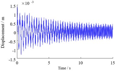
The vibration of the coal shearer when cutting the coal and rock, operation of backfilling conveyor and tamping institution will affect the hydraulic support. These vibration sources propagate through coal and rock mass in the form of stress waves to the hydraulic support. Because of the complex nature of coal and rock mass, the disturbance of the hydraulic support has strong randomness. In the dynamic analysis of hydraulic support, the external excitation can be simplified to harmonics with different amplitudes, frequencies and phase angles. According to the research in the literature [15-17], it is known that the dominant frequency of the disturbance generated by the coal shearer cutting is within the low frequency bandwidth of less than 120 rad/s, the backfilling conveyor and the compaction of the compactor also have low frequency properties. Based on the system of differential equations and state space models, the fourth-order-five-order Runge-Kutta algorithm is used to solve the differential equations. The time-domain response of the vertical vibration of the top beam at 20 rad/s is shown in Fig. 4.The original static equilibrium of the hydraulic support is broken by the disturbance, the top beam has a transient violent vibration within 0-0.35 s, the maximum amplitude is about 17.7 mm, and then the vibration frequency and the disturbance frequency are gradually consistent under the action of hydraulic damping. The violent vibration easily causes the fatigue of the connecting pin between the top beam and the pillar. In order to reduce the vibration of the top beam, the number and position of hydraulic pillars can be optimized.
Fig. 4Vertical vibration response of top beam
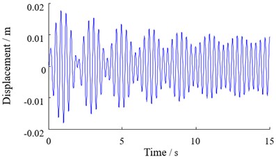
Fig. 5Roll and pitch vibration response of top beam
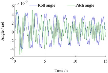
The time domain response of the top beam to pitch and roll vibration is shown in Fig. 5. It can be seen from Fig. 5 that the pitch vibration of the top beam has a great fluctuation under the action of disturbance, and its maximum amplitude is about 5.5×10⁻³ rad .The roll vibration is relatively small, and its maximum amplitude is about 4.3×10⁻³rad. Under the continuous action of disturbance the lateral amplitude of the top beam is slightly higher than the pitch amplitude, but the degree of vibration can be maintained in a controllable range. It will not have a destructive effect on the system.
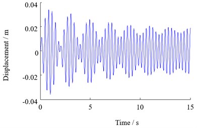
In order to study the influence of disturbance frequency on the hydraulic support, the dynamic characteristics of the top beam are studied when the disturbance frequency varies from 20 to 80 rad/s, and the vibration response of the top beam is obtained as shown in Fig. 6. It can be seen from Fig. 6 that the top beam has a nonlinear violent vibration at the initial moment. As the disturbance frequency increases, the change in the displacement of the top beam caused by the vibration is reduced, and the amplitude eventually exhibits a periodic variation within a certain range.
The vibration of the top beam under different disturbance frequencies is obtained by the statistics of the top beam displacement, the roll angle and the pitch angle when the disturbance is changed in the range of 20 rad/s-80 rad/s as shown in Fig. 7. It can be seen that the vertical vibration of the top beam decreases gradually with the increase of the disturbance frequency, but the amplitude of the decrease tends to be gentle; the variation trend of the lateral vibration of the support is similar to that of the vertical vibration, but the variation of pitching vibration with the change of the frequency is not particularly obvious.
Fig. 6Vertical vibration response of top beam with different disturbance frequency
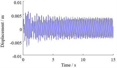
a) 40 rad/s
b) 60 rad/s
c) 80 rad/s
Fig. 7The relationship between the beam vibration and disturbance frequency
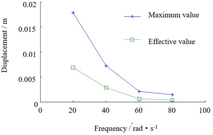
a) Variation of top beam displacement with disturbance frequency
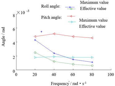
b) The variation of the top beam angle with disturbance frequency
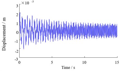
Fig. 8Vertical vibration response of top beam with different disturbance amplitude
a) 15×103N
b) 20×103N
Fig. 9The relationship between the beam vibration and disturbance amplitude
a) Variation of top beam displacement with disturbance amplitude
b) Variation of top beam angle with disturbance amplitude
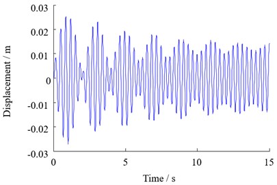
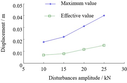
The dynamic characteristics of the system are studied when the external disturbance is 15 kN, 20 kN and 25 kN respectively. The vertical vibration response of the lower beam is obtained as shown in Fig. 8. It can be seen that as the amplitude of the disturbance increases, the vibration of the top beam is more severe.
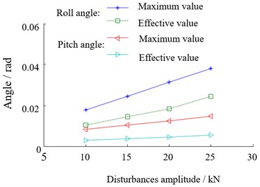
Based on the statistics of the top beam displacement, roll angle and pitch angle, the vibration of the top beam under different disturbances changes as shown in Fig. 9. Vertical, lateral and pitch vibration of the top beam become more and more severe with the increase of the external disturbance, and the maximum amplitude of increase is more obvious than the effective value. The magnitude of external disturbance has a more significant effect on the vertical and lateral vibration of the top beam, but less on the pitching vibration.
5. Finite element analysis
According to the design drawings, the backfilling hydraulic support is modeled by Solidworks software, and then imported into ANSYS software through special interface. The model is meshed as shown in Fig. 10. When the disturbance frequency is 80 Hz, the deformation distribution of the top beam is shown in Fig. 11. The large deformation area mainly concentrates in the middle of the top beam, and presents a symmetrical variation law.
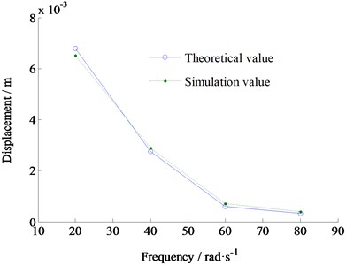
By applying external disturbances of different frequencies, the variation of the displacement of the top beam with frequency is obtained as shown in Fig. 12. It can be seen that the results obtained by the theoretical model are basically consistent with the results obtained obtained by the finite element method, which proves the correctness of the model.
Fig. 10Mesh generation of backfilling hydraulic support with six pillars
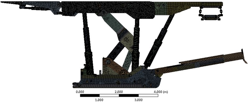
Fig. 11Deformation distribution of top beam
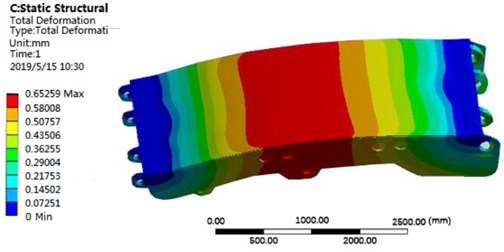
Fig. 12Comparison of the results of two methods
6. Conclusions
A roof support and backfilling equipment for the goaf was designed. The structure of the backfilling hydraulic support with six pillars and its working principle are introduced. The important effect of backfilling hydraulic support on improving the stress state of the overburden layer above the goaf and restraining the subsidence of the roof was expounded.
Based on the Lagrangian method, a differential equation of motion and a state space model of backfilling hydraulic support were established. The fourth-fifth order Runge-Kutta algorithm were used to solve the differential equation, and the dynamic response of the support under different disturbance frequencies and amplitudes was obtained. It is found that the vertical, lateral and pitch vibrations of the top beam fluctuate greatly at the moment of disturbance, then gradually stabilize and exhibit periodic vibration consistent with the disturbance frequency. With the increase of disturbance frequency, the vertical and roll vibration of the top beam decreases gradually, while the change of disturbance frequency has little effect on the pitch vibration of the top beam.
Through the finite element analysis of the model of the backfilling hydraulic support, the deformation distribution nephogram of the top beam is obtained. The results show that the finite element analysis data are consistent with the theoretical analysis data, which proves the correctness of the dynamic model.
References
-
Senapati P. K., Mishra B. K. Design considerations for hydraulic backfilling with coal combustion products (CCPs) at high solids concentrations. Powder Technology, Vol. 229, Issue 6, 2012, p. 119-125.
-
Karfakis M. G., Bowman C. H., Topuz E. Characterization of coal-mine refuse as backfilling material. Geotechnical and Geological Engineering, Vol. 214, Issue 2, 1996, p. 129-150.
-
Li L., Aubertin M. An improved analytical solution to estimate the stress state in subvertical backfilled stopes. Canadian Geotechnical Journal, Vol. 45, Issue 45, 2008, p. 1487-1496.
-
Zhou Y. J., Zhang J. X., Nie S. J., et al. Mechanical analysis and kinematic simulation of a hydraulic support used in backfilling and the coal mining face. Journal of China University of Mining and Technology, Vol. 41, Issue 3, 2012, p. 366-370.
-
Xu J. M., Tan F. Q., Feng J. U., et al. Principle and structure of backfill supports with six props. China Mining Magazine, Vol. 20, Issue 4, 2011, p. 101-104.
-
Xu J. M., Zhang J., Zhou N., et al. Effect factors on equivalent mining height in fully mechanized backfilling mining with solid materials. China Coal, Vol. 37, Issue 3, 2011, p. 66-68.
-
Gong P., Jin Z. Research on influencing factors of tilt for fully-mechanized mining support with large mining height. Journal of Taiyuan University of Technology, Vol. 32, Issue 6, 2001, p. 666-669.
-
Jiang D. H., Gong P. L., Du Z. D. Confirmation of rating working resistance of hydraulic support in residual coal mining passed through empty roadway group. Coal Mine Machinery, Vol. 36, Issue 2, 2015, p. 210-212.
-
Qi F. K., Zhou Y. J., Wang E. Q., et al. Mechanical analysis of new backfill hydraulic support with four pillars. Mining Research and Development, Vol. 36, Issue 1, 2016, p. 90-93.
-
Miao X. X., Zhang J. X. Key technologies of integration of coal mining-gangue washing-backfilling and coal mining. Journal of China Coal Society, Vol. 39, Issue 8, 2014, p. 1424-1433.
-
Zhang Q., Zhang J., Tai Y., et al. The theoretical research on basic characteristics of backfilling hydraulic support and its application. Journal of Mining and Safety Engineering, Vol. 31, Issue 6, 2014, p. 845-851.
-
Lu J. N., Mao J., Xie M., et al. Dynamics model of advanced powered support in heading under full support situation. Journal of China Coal Society, Vol. 40, Issue 1, 2015, p. 50-57.
-
Fang Z. F., Deng Z. X. Research on the state space model of vehicle vibration system. China Mechanical Engineering, Vol. 16, Issue 4, 2005, p. 353-354.
-
Yang S., Wang T. Y. Dynamic modeling and analyzing of a large-scale nonlinear resonance screen. Journal of China Coal Society, Vol. 34, Issue 3, 2009, p. 405-409.
-
Zhang Q., Zhang J. X., Ju F., et al. Backfillbody’s compression ratio design and control research insolid backfill coal mining. Journal of China Coal Society, Vol. 39, Issue 1, 2014, p. 64-71.
-
Tiryaki B., Hekimoglu O. Z. Effects of drum vibration on performance of coal shearers. Transactions of the Institution of Mining and Metallurgy, Vol. 106, 1997, p. 91-94.
-
Luan L. J., Fan Fu M., Gao J. S., et al. Design and research on discharge hole of porous bottom unloading conveyor. Coal Mine Machinery, Vol. 37, Issue 11, 2016, p. 5-7.
Cited by
About this article

The authors are grateful for the funding of this work by National Natural Science Foundation of China (No. 51674134) and Scientific and Technological Research Projects of Henan Province (182102210606).
