Abstract
In order to study the layout and developments of pressure pulsation of the main flow passage component in magnetic drive pump, the full flow field numerical research of magnetic drive pump was done with CFX software, the pressure pulsation character of cooling circulating channel and external characteristic curve of pump were obtained. The reliability of the numerical calculation method is verified by the external characteristic test, and the pressure pulsation characteristics in the main flow components of the magnetic drive pump are studied. The results show that the main source of pressure pulsation in magnetic drive pump is the dynamic and static interference between impeller channel, pressurized water chamber and baffle tongue; the main frequency of cooling circulating channel is blade frequency and the pressure fluctuation amplitude of cooling circulation channel decreases with the increase of flow and the propagation of pressure fluctuation in cooling circulation channel weakens the intensity of pressure fluctuating.
Highlights
- The reliability of the numerical calculation method is verified by the external characteristic test.
- The pressure pulsation characteristics in the main flow components of the magnetic drive pump are studied.
- The main source of pressure pulsation in magnetic drive pump is the dynamic and static interference between impeller channel, pressurized water chamber and baffle tongue.
- The pressure pulsation amplitude at the reflow hole and pump inlet is small, and the pressure pulsation attenuation at each monitoring point in the reflow hole is obvious.
- The pressure pulsation in the cooling circulating flow passage mainly comes from the dynamic and static interference between the impeller channel, the pressurized water chamber and the baffle tongue.
1. Introduction
The unsteady time-series interaction between the impeller and the pressurized water chamber, the water flow impact at the inlet of the blade, the pressure change caused by the off-flow at the outlet of the blade and the discontinuity of the flow caused by cavitation when the blade deviates from the optimum operating condition, cause pressure changes, etc. all these factors may lead to the constant change of the medium pressure in the magnetic drive pump with time, that is to say, it appears: Pressure pulsation [1-4]. Pressure pulsation in magnetic drive pump can be divided into three types according to its manifestation: shaft frequency multiple-frequency pulsating, blade frequency multiple-frequency pulsating and random pulsation. The frequency of shaft frequency multiple-frequency pulsating is multiple of rotational frequency or shaft frequency, the frequency of blade frequency multiple-frequency pulsating is integral multiple of blade frequency or blade frequency, and the frequency of random pulsation approximate to white noise [5-7].
It was found that the main causes of pressure pulsation in magnetic drive pump are the static and dynamic interference in the magnetic drive pump and the uneven outflow of impeller channel, by summarizing the research on pressure pulsation in magnetic drive pump field by many scholars at home and abroad [8-13]. The appearance of pressure pulsation will lead to vibration, noise and hydraulic excitation of the whole pump set, and in serious cases, it will lead to local cavitation-erosion or resonance in the pump set, which will affect the stable operation of the pump set [14, 15]. In addition, in the magnetic drive centrifugal pump, the pressure pulsation generated by the static and dynamic interference will propagate along with the cooling circulating medium in the cooling channel. If the pressure pulsation can’t be rapidly attenuated, it will bring a large alternating load to the isolation sleeve and bearing, and then lead to the wear and fatigue failure of the various over-current components and other security risks. Therefore, it is of great significance to study the distribution law of pressure pulsation in cooling circulating passages of magnetic drive pump.
Previous studies on magnetic pump mainly focus on the transmission characteristics of magnetic coupling, eddy current heating of isolation sleeve and operation monitoring [16-22], and there are few studies on the cooling loop of magnetic pump. Tong Xiaoyu et al. [23] discussed the optimal design of the internal circulation amount and circulating aperture of the magnetic pump, and verified the different apertures through examples. Kong Fanyu et al. [24] combined the cooling loop with the axial force balance design and applied it to the high-speed magnetic pump, achieving good engineering application results. Liu Jianrui et al. [25] simulated the flow field of the inner loop of the magnetic pump, indicating that the viscous bottom layer of the medium at the bottom of the isolation sleeve is the main cause of vaporization of volatile medium. Many scientific researchers have analyzed different flow fields and temperature fields, providing useful references for the design of magnetic pump cooling loop [26-28].
In this paper, the unsteady numerical calculation method is adopted to obtain the pressure pulsation values of each monitoring point under different working conditions, and the distribution and variation law of pressure pulsation characteristics in the main flow passage components of the magnetic-driven centrifugal pump are analyzed and studied in depth.
2. Research object
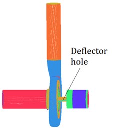
The basic design parameters of the magnetic driving centrifugal pump are: Flow 250 m3/h, Lift 36 m, rated speed 1450 r/min, efficiency 71 %. The calculation area of magnetic drive centrifugal pump includes the inlet extension section, impeller, pressurized water chamber, magnetic drive coupling, pump front-cavity, pump back-cavity, bearing clearance, deflector hole, reflux hole, pump outlet extended section and so on. In this paper, Pro/E software is used to conduct three dimensional modeling of all over flow parts of the magnetic drive pumps, ICEM-CFD software is used to divide grids, the 3D solid model of the main overcurrent parts is shown in Fig. 1, the grid layout is shown in Fig. 2.
Fig. 1The regions and mesh generation of magnetic drive pump
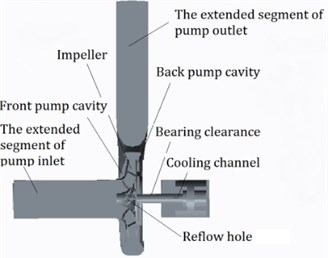
Fig. 2The meshing figure
At present, the calculated values of lift and efficiency are mostly used as the judgment criteria in the numerical simulation of pump. When the number of grids keeps increasing and the calculated values of lift and efficiency gradually become stable, it indicates that the calculation results are no longer affected by the number of grids and it is not necessary to continue to increase the number of grids. Therefore, in this paper, the efficiency and head under the design condition of magnetic driven centrifugal pump are adopted as the evaluation criteria of grid independence, and 6 schemes with different amounts of grids are divided, as shown in Table 1. As can be seen from Table 1, when the total number of grids is greater than 5618310, the calculated values of lift and efficiency no longer change significantly with the number of grids. In order to ensure the accuracy of numerical calculation and to save calculation cost and time, plan 5 was finally selected for subsequent calculation, and the total number of calculation grids for magnetic driven centrifugal pump was determined to be 5618310.
Table 1Grid scheme
Scheme | 1 | 2 | 3 | 4 | 5 | 6 |
Bearing clearance | 23846 | 41725 | 76138 | 128637 | 190380 | 371560 |
Pump inlet | 15608 | 32491 | 73592 | 135871 | 173502 | 289683 |
Deflector hole | 8905 | 18307 | 26819 | 39756 | 50803 | 82937 |
Reflow hole | 15472 | 27697 | 39671 | 59824 | 90857 | 156870 |
The total number of grid | 865644 | 1527165 | 2480569 | 3716032 | 5618310 | 8027541 |
Lift / m | 37.39 | 36.82 | 36.53 | 36.17 | 36.03 | 36.02 |
Efficiency / % | 78.25 | 77.32 | 76.36 | 75.11 | 74.43 | 74.41 |
2.1. Numerical calculation and analysis method
Unsteady computation takes the result of steady flow field as the initial condition. In the unsteady calculation, the rotational position of the impeller's rotational domain relative to the stationary domain corresponds to the time step one by one. The results of the previous step are used as the initial values for the next step. Therefore, in order to guarantee the accuracy and efficiency of unsteady numerical computation, it is necessary to choose the appropriate calculation step, refer to the calculation settings in reference [31-33], In order to ensure the accuracy of unsteady numerical calculation, the sampling frequency of real-time pressure value is 20 times of blade passing frequency. Impellers’ rotational speed 1450 r/min, take the impeller 360 degrees for a calculation cycle . It can be calculated 0.041379 s, take one step at a time 3.448e-4, a cycle takes 120 time steps, and the impeller rotates 3 degrees at each time step, the total time taken in this paper is 10. Simulation results show that, the variation of unsteady flow field after 4 cycles meets the periodic requirement, and the last monitoring point of calculation cycle is extracted to analyze the pressure fluctuation. There are two main methods to deal with the data of pressure fluctuation calculated by unsteady values: time-domain analysis and frequency-domain analysis. Frequency domain analysis is mainly to transform the originally collected signal into frequency domain signal for analysis and processing through Fourier transform of the monitoring value of monitoring point, so as to quickly find the correlation between the collected signals. In time-domain analysis, the concept of pressure fluctuation coefficient is introduced in order to more intuitively reflect the change of pressure fluctuation at monitoring points and avoid the interference of static pressure value of monitoring points on the judgment of pressure fluctuation [34-36]. The formula is:
In the form of: is the static pressure value at the monitoring point, is the average pressure in a rotating period, is the medium density, is the circumferential velocity at the outlet of the impeller.
The commercial CFD software can provide different turbulence model for researchers to study the flow field of pump at present. The four kinds of turbulence models were adopt for the calculation of inter flow in magnetic drive pump, and the comparative results between numerical calculation and test results with different turbulence models under design condition were shown in Table 2.
Table 2The results of numerical calculation compared with test results with different turbulence model
Turbulence model | Standard - | RNG - | Standard - | SST - | Test result |
Lift /m | 36.82 | 36.79 | 35.96 | 36.03 | 36.31 |
Efficiency / % | 74.71 | 74.63 | 74.57 | 74.43 | 71.18 |
As we can see from Table 1, the numerical results with Standard - model, SST - model are most close to the test value, and the results with Standard - model and RNG - model are higher than test value. SST - model has obvious advantages in the calculation of tip clearance flows with smaller size, and the numerical calculation of total flow field in magnetic drive pump involves too much calculations about tip clearance flows with smaller size, so the SST - model was adopted as the turbulence model in this paper.
The inlet boundary condition was set as the mass flow rate boundary condition, and the outlet boundary condition was the pressure boundary condition, then the solid wall was set as no slip wall, and automatic wall function method was adopted near the wall. The impeller was set as rotary body, then the cooling channel, front pump cavity, back pump and bearing clearance were cavity non-rotary body. The wall surfaces of cooling channel, front pump cavity, back pump cavity and bearing clearance in contact with rotating parts were set as rotating surfaces whose rotary speed was pump speed, and the wall surfaces in contact with fixing parts were stationary surfaces. The rotor-stator interactional surfaces between rotary body and non-rotary body were adopt as frozen rotor, and it plays an important role for dynamic static coupling between rotary body and non-rotary body. GGI mode of CFX software was chosen for the relation between interface grids, and the thermal model was selected for heat transfer.
3. Setting of monitoring points
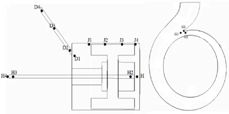
In order to accurately grasp the transient flow characteristics of magnetic drive pump under different working conditions, monitoring points are arranged in each main flow channel to monitor the pressure fluctuation. It can be seen from the above literature that the main cause of pressure pulsation in the magnetic drive pump is the rotor-stator interference within the magnetic drive pump, so three monitoring points, G1, G2 and G3, are arranged near the volute tongue of the pressurized water chamber to monitor the pressure fluctuation caused by the dynamic and static interaction between the volute tongue and the impeller near the volute tongue. Monitoring points D1, D2, D3, D4, J1, J2, J3, J4 and H1, H2, H3, H4 are arranged in the deflector hole, the gap between isolation sleeve and the reflux hole respectively to monitor the development and change of pressure fluctuation in the cooling circulating channel. Monitoring points I1 and I2 are arranged near the inlet of impeller to monitor the pressure fluctuation at the inlet of magnetic drive centrifugal pump. The distribution and location of some main monitoring points are shown in Fig. 3.
Fig. 3The layout of the supervision point in magnetic drive pump
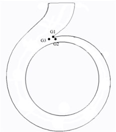
a) The layout of the supervision point in volute
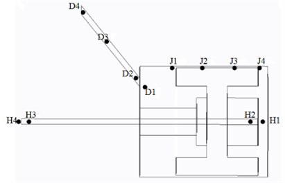
b) The layout of the supervision point in cooling circulating channel
4. Analysis of external characteristics
Fig. 4 is a comparison chart of unsteady numerical calculation, constant numerical calculation and test result curve of magnetic drive centrifugal pump. As shown in Fig. 4, the results of unsteady numerical calculation and constant numerical calculation do not differ much from those of test results, and the general trend of change and mutual coincidence are preferably. Under the design condition, the constant numerical calculation and unsteady numerical calculation are very close to the test head value, and the efficiency value of unsteady numerical calculation efficiency is more close to the test value. It shows that the unsteady numerical calculation can better reflect the internal flow state of the magnetic drive centrifugal pump, the numerical calculation results are relatively accurate, and the numerical calculation method is reliability.
Fig. 4The unsteady numerical results of magnetic drive pump
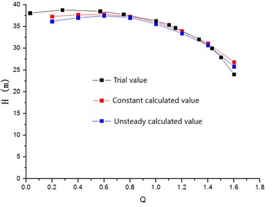
a)- characteristic curves
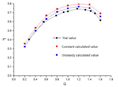
b)- characteristic curves
5. Study on pressure pulsation characteristics
5.1. Study on pressure pulsation near the volute tongue
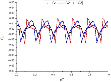
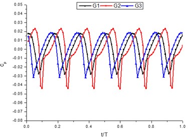
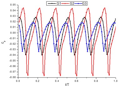
The time-domain diagram of pressure fluctuation coefficient near the volute tongue under different working conditions is shown in Fig. 5. As can be seen from Fig. 5, the pressure fluctuation coefficients of each monitoring point have obvious periodic changes under three working conditions, and the changes are similar, that is, the pressure fluctuation coefficients of each monitoring point show six wavy shape changes in a rotating period. The amplitude of pressure fluctuation coefficient at G2 point is larger than that at G1 point and G3 point, indicating that the turbulence characteristics at G2 point are more obvious, and the pressure fluctuation characteristics near G2 point are more obvious than those at other monitoring points.
With the increase of flow rate, the amplitude of pressure fluctuation coefficient at G1, G2 and G3 points increases gradually. The amplitude of pressure fluctuation coefficient at G3 point changes slightly, and the amplitude of pressure fluctuation at G2 point and G1 point changes greatly. The larger the flow rate, the greater the difference between the G2 point and the pressure fluctuation amplitude of G1 and G3 points. At 0.6, the fluctuation coefficients of G2 point are different from those of G1 and G3, the amplitude of pressure fluctuation coefficients of G2 point is the largest and that of G1 point is the smallest. At 1.0, the amplitude of pressure fluctuation coefficient of G2 is the largest, and the amplitude of pressure fluctuation coefficient of G1 and G3 is basically the same. At 1.4, the amplitude of pressure fluctuation coefficient of G2 is the largest, and the amplitude of pressure fluctuation coefficient of G1 is greater than that of G3, which is mainly because of the G3 point is located in the front of the volute tongue. When the impeller rotates to the volute tongue, the medium flowing out of the impeller channel at high speed sweeps through the G3 monitoring point first. Because the G3 monitoring point is located in the front of the volute tongue, the impeller channel has not interfered with the volute tongue, so the pressure fluctuation amplitude is small. As the impeller continues to rotate, the impeller channel sweeps through G1 point, and the impeller channel begins to dynamic and static interaction with the volute tongue. At this time, the amplitude of pressure fluctuation at G1 point increases. With the impeller continues to rotate, the impeller channel first passes through G2 point after sweeping the volute tongue. Therefore, G2 point is most affected by the static and dynamic interference between the impeller channel and the volute tongue, the amplitude of pressure pulsation coefficient and its amplitude variation is the greatest. Based on the above analysis and the same number of waveforms and impellers in a cycle, it can be inferred that the pressure fluctuation near the volute tongue is mainly caused by the static and dynamic interaction between the impeller channel and the volute tongue during the rotating process of the impeller, that is, each channel of the impeller is equivalent to a source of dynamic and static interaction on the volute tongue.
Fig. 5The time-domain plot of pressure fluctuation intensity coefficient near volute tongue under different conditions
a) 0.6
b) 1.0
c) 1.4
Compared with the three operating points of 0.6, 1.0 and 1.4, as the flow rate changes, the amplitude of pressure fluctuation coefficient at G2 point varies greatly. Combining with the analysis of Fig. 8, it can be concluded that this is mainly due to the pressure alternating change caused by the interaction between impeller and volute tongue near G2 point. The time step position of G1 and G3 point pressure fluctuation coefficient has basically remained unchanged. Comparing with 0.6 and 1.0, the time step of pressure fluctuation coefficient amplitude at G2 point changes greatly with the flow rate. Comparing with 1.0 and 1.4, the time of amplitude of pressure fluctuation coefficient at G2 has not changed, and the variation law of pressure fluctuation coefficient waveform at G2 is gradually similar to that at G1 and G3. The analysis shows that the main reason is that the medium flow in impeller and pressurized water chamber is more disordered under the condition of small flow rate, and there may be more unstable flow phenomena such as reflux, off-flow and secondary flow near G2 point, which results in the variation rule of pressure fluctuation of G2 point is different from that of G1 and G2 point under the condition of small flow rate. Under the design and large flow conditions, the flow channel of impeller and pressurized water chamber is gradually filled with medium, and the flow of medium is more regular. The variation rule of pressure fluctuation coefficient of G2 is similar to that of G1 and G3.
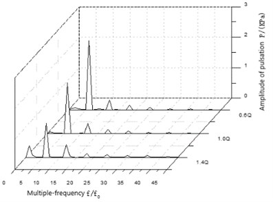
Fig. 6The wave in frequency domain of pressure fluctuation near volute tongue under different conditions
a) 0.6
b) 1.0
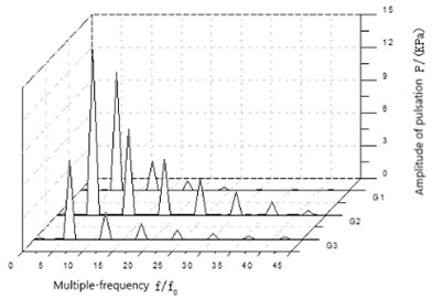
c) 1.4
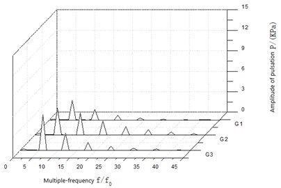
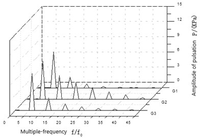
Fig. 6 is a frequency domain diagram of pressure fluctuation on each monitoring point near the volute tongue under different working conditions. As shown in Fig. 6, the main pulsation frequency of pressure pulses on each monitoring point near the volute tongue is 6 ( 1450/60). When the frequency of each frequency division signal is the multiple of the blade frequency of the impeller, the pressure fluctuation amplitude of each frequency division appears peak value. With the increase of frequency, the pressure fluctuation amplitude of each frequency division signal decreases gradually until 0. Under the condition of small flow rate, the pressure fluctuation amplitude at the main frequency of monitoring point G3 is the largest, and that at G1 is the smallest. In addition, there are more low-frequency signals arisen at each monitoring point when small flow conditions are running (1), With the increase of flow rate, the low-frequency signal gradually disappears, and the amplitude of pressure fluctuation of G1, G2 and G3 main frequencies and each frequency division signal gradually increases. Among them, the amplitude of pressure fluctuation of G2 is the most obvious. The amplitude of pressure fluctuation at G2 point is basically the same as that at G1 and G3 under design condition. At high flow condition, the amplitude of pressure fluctuation at G2 point is much larger than that at G1 point and G3 point. To sum up, the main frequency of monitoring points near the volute tongue is impeller blade frequency. Under design and large flow conditions, according to the sequence of passage of impeller, the amplitudes of main frequency pressure fluctuation at each monitoring point are G3, G1 and G2, respectively. G3 is the smallest and G2 is the largest. This shows again that the pressure fluctuation source near the volute tongue is the dynamic and static interaction between impeller channel and volute tongue.
5.2. Study on pressure pulsation in deflector hole
The time-domain diagram of pressure pulsation coefficient of each monitoring point in the deflector hole under different working conditions is shown in Fig. 7. As can be seen from Fig. 7, the pressure pulsation coefficient of each monitoring point in the deflector hole presents a distribution of 6 waveforms, and the magnitude of the amplitude of pressure fluctuation coefficients of each monitoring point is D4, D3, D2 and D1 in turn, that is, the amplitude of pressure pulsation coefficient decreases successively along the direction from the inlet to the outlet of the deflector hole. The amplitude of pressure pulsation coefficient in the condition of small flow is larger. With the increase of flow, the amplitude of pressure pulsation coefficient in each monitoring point gradually decreases, but the variation of the amplitude of pressure pulsation coefficient in the deflector hole in different working conditions is very small, about 0.001. In addition, it can be seen from Fig. 13 that the time step of the amplitude appears of pressure pulsation coefficient in the four monitoring points in the deflector hole is basically the same. Based on the above analysis results of pressure pulsation time domain, it can be preliminarily determined that the pressure pulsation source in the deflector hole mainly comes from the inlet of the deflector hole, and the pressure pulsation passes through the deflector hole and attenuates in the process of propagation. Therefore, the amplitude of pressure pulsation coefficient at the monitoring point at the outlet of the deflector hole is smaller than that at the inlet of the cooling circulating channel.
Fig. 7The time-domain plot of pressure fluctuation intensity coefficient of deflector hole under different conditions
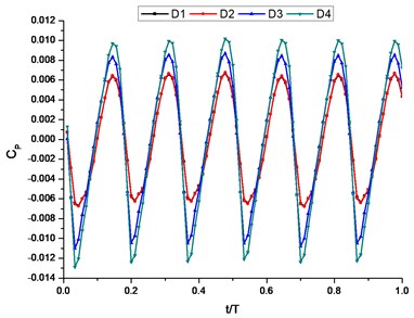
a) 0.6
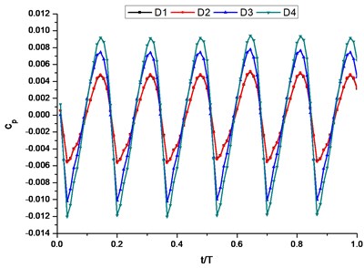
b) 1.0
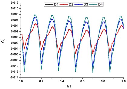
c) 1.4
Fig. 8 shows the pressure pulsation frequency domain of each monitoring point in the deflector hole under different working conditions. It can be seen Fig. 8 shows that the main frequency of pressure pulsation at each monitoring point in the deflector hole is 6.When the frequency is a multiple of 6, the frequency division reaches a peak. Along the inlet of the deflector hole to the outlet, the main frequency amplitude of pressure pulsation of each monitoring point in the deflector hole gradually decreases, and the pressure pulsation amplitude of each monitoring point gradually decreases. In addition, with the increase of flow rate, the pressure pulsation amplitude of low-frequency signals at each monitoring point gradually increases, indicating that the influence of shaft frequency on pressure pulsation gradually increases with the increase of flow rate. According to the above analysis, combined with the analysis results of pressure pulsation at the monitoring points near the baffle tongue and the base circle of the pressurized water chamber, and referring to the above time-domain analysis results of pressure pulsation at the monitoring points in the deflector hole, it can be preliminarily concluded that the main source of pressure pulsation in the deflector hole is the dynamic and static interaction between impeller, pressurized water chamber and baffle tongue. Therefore, the amplitude of pressure pulsation in each monitoring point in the deflector hole decreases with the increase of flow rate, which is consistent with the analysis result in Fig. 7. What’s more, the comprehensive analysis of Fig. 8 shows that the pressure pulsation amplitude in the deflector hole gradually decreases along the direction from the inlet to the outlet of the deflector hole, which also reflects the attenuation process of pressure pulsation in the propagation in the deflector hole.
Fig. 8The wave in frequency domain of pressure fluctuation of deflector hole under different conditions
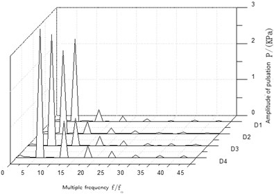
a) 0.6
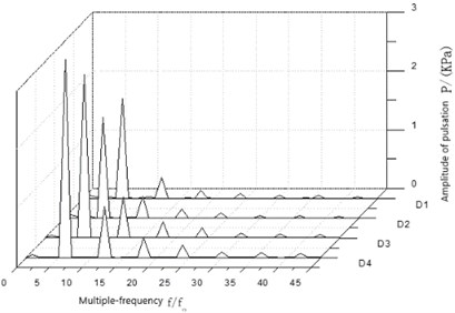
b) 1.0
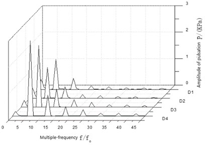
c) 1.4
5.3. Study on pressure pulsation in isolation sleeve clearance
In the process of processing pressure pulsation data of isolation sleeve clearance, it is found that the variation of pressure pulsation coefficient and amplitude of pressure pulsation at each monitoring point in the isolation sleeve clearance is basically similar to that in the deflector hole, that is, the amplitude of pressure pulsation coefficient and amplitude of pressure pulsation gradually decrease along the direction from the inlet to the outlet of isolation sleeve clearance. Due to the limitation of the length of this paper, only J2 point is selected as the representative point for research. The pressure pulsation time-domain diagram of J2 point in isolation sleeve clearance under different working conditions is shown in Fig. 9, and the pressure pulsation frequency domain diagram is shown in Fig. 10. As can be seen from Fig. 9, the pressure pulsation coefficient at point J2 presents 6 waveforms. In different operating conditions, the time step of the amplitude appears of pressure pulsation coefficient is basically the same; at the condition of 0.6, the amplitude of pressure pulsation coefficient at point J2 is the largest; as the flow rate increases, the amplitude of pressure pulsation coefficient gradually decreases; under the condition of 1.4, the amplitude of pressure pulsation coefficient is the minimum. As can be seen from Fig. 10, the main frequency of pressure pulsation at point J2 is 6. With the increase of flow rate, the amplitude of pressure pulsation gradually decreases and the low-frequency signal gradually increases, indicating that the influence of shaft frequency on pressure pulsation in isolation sleeve clearance gradually increases under the condition of large flow rate. In addition, compared with the amplitude of pressure pulsation coefficient and pressure pulsation amplitude at each monitoring point near the deflector hole and baffle tongue, the amplitude of pressure pulsation coefficient and pressure pulsation amplitude at J2 point are significantly reduced, which again illustrates the attenuation process of pressure pulsation in the propagation in the cooling circulating channel.
Fig. 9The time-domain plot of pressure fluctuation intensity coefficient of J2 under different conditions
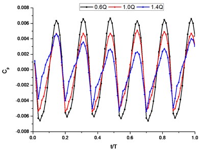
Fig. 10The wave in frequency domain of pressure fluctuation of J2 under different conditions
5.4. Study on pressure pulsation in reflow hole
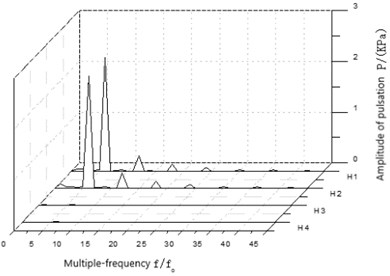
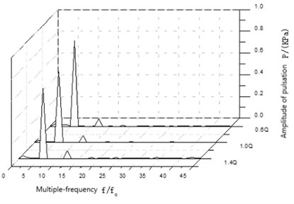
In the process of processing pressure pulsation data of reflow hole, it is found that the variation trend of pressure pulsation coefficient and pressure pulsation amplitude of each monitoring point in the reflow hole is basically the same under different working conditions. Only the pressure pulsation coefficient amplitude and pressure pulsation amplitude of H1 and H2 points are slightly different. Therefore, the design working condition point is selected as the typical working condition point for analysis. The time-domain diagram of pressure pulsation in the reflow hole under design conditions is shown in Fig. 11, and the frequency domain diagram of pressure pulsation in the reflow hole under design conditions is shown in Fig. 12. As can be seen from Fig. 11, the amplitude of pressure pulsation coefficient at H1 and H2 is evenly distributed in 6 waveforms. The amplitude of pressure pulsation coefficient at H1 and H2 is almost the same, and the pressure pulsation time-domain at H3 and H4 fluctuates very little, almost in a straight line. It can be seen from Fig. 12 that the pressure pulsation amplitude of each monitoring point in the reflow hole gradually decreases along the direction from the inlet of the reflow hole to the impeller inlet. The main frequency of pressure pulsation at H1 and H2 is 6, indicating that the pressure pulsation at these two points is mainly affected by blade frequency. Although the pressure pulsation at H3 and H4 is also 6, the difference between the low-frequency amplitude and the main frequency amplitude is not obvious, indicating that the pressure pulsation at these two points is still mainly affected by the blade frequency, and the axial frequency also has a great influence on the pressure pulsation. In addition, the amplitude variation law of pressure pulsation in the reflow hole under the design condition just verifies the attenuation process of pressure pulsation in the reflow hole. A comprehensive analysis of the pressure pulsation time domain and frequency domain of each monitoring point near the baffle tongue, deflector hole, isolation sleeve clearance and reflow hole shows that the pressure pulsation in the cooling circulating flow passage is mainly caused by the dynamic and static interference between the impeller channel and the pressurized water chamber and the baffle tongue. During the propagation of the pressure pulsation in the cooling circulating passage, the pulsation amplitude is gradually smaller and the pressure pulsation is gradually attenuated. During the whole process of pressure pulsation attenuation, the change of pressure pulsation in the gap of the spacer sleeve has the most important impact on the spacer sleeve. If the pressure pulsation in the gap of the spacer sleeve is large, it will cause the spacer sleeve to bear a large alternating load and seriously affect the service life and operation stability of the spacer sleeve. In the propagation process of pressure pulsation in the cooling circulation passage, blade frequency is the main factor affecting the pressure pulsation in the cooling circulation passage. However, as the pressure pulsation propagates and decays in the cooling circulation passage, axial frequency has an increasingly greater influence on the pressure pulsation in the cooling circulation passage.
Fig. 11The time-domain plot of pressure fluctuation intensity coefficient of reflux hole under design condition
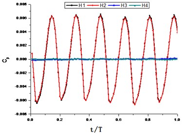
Fig. 12The wave in frequency domain of pressure fluctuation of reflux hole under design condition
5.5. Study on pressure pulsation at pump inlet
In the process of processing the pressure pulsation data of the pump inlet, it is found that the pressure pulsation coefficient, the value of parameters and the variation trend of the pressure pulsation amplitude of the two monitoring points at the pump inlet are basically the same. Therefore, point I2 is selected as the representative point for the pressure pulsation analysis. The time-domain diagram of pressure pulsation coefficient at monitoring point I2 at the pump inlet under different working conditions is shown in Fig. 13, and the frequency-domain diagram of pressure pulsation at monitoring point I2 at the pump inlet under different working conditions is shown in Fig. 14. As can be seen from Fig. 13, the variation of pressure pulsation coefficient at the pump inlet presents six undulations in a rotation cycle. The pressure pulsation coefficient amplitude at monitoring point I2 is small, only about 0.002. However, the change of flow has little influence on the amplitude of pressure pulsation coefficient at monitoring point I2. As can be seen from Fig. 14, the main frequency of pressure pulsation at monitoring point I2 is 6, that is, blade frequency is the main factor affecting the pressure pulsation at point I2. Compared with other flow passage components studied above, the pressure pulsation amplitude at I2 is small, only about 0.8. The pressure pulsation amplitude is the largest at 0.6, and gradually decreases at I2 as the flow rate increases, while the pressure pulsation amplitude is the smallest at 1.4.
Fig. 13The time-domain plot of pressure fluctuation intensity coefficient of I2 under different conditions
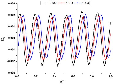
Fig. 14The wave in frequency domain of pressure fluctuation of I2 under different conditions
6. Study on static pressure distribution in pump
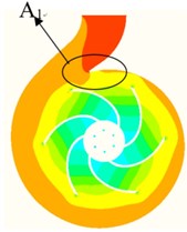
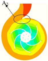
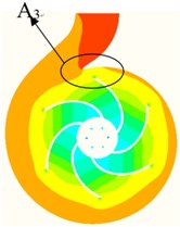
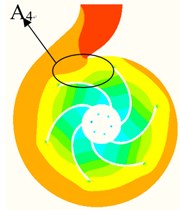
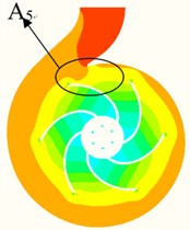
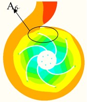
Static pressure distribution of the section in the pump at different times under design conditions is shown in Fig. 15. As can be seen from Fig. 15, the relative position of the impeller channel and the volute tongue is different at different times.
Fig. 15The static pressure distribution in middle section of magnetic drive pump in different time under design condition
a) 0
b) 1.24
c) 2/24
d) 3/24
e) 4/24
f) 5/24

During the approach and sweep of the volute tongue by a single impeller, the pressure in the area near the volute tongue changes alternately as the impeller sweeps the tongue due to the dynamic and static interaction between the impeller's flow channel and the volute tongue and the pressurized water chamber, causing the pressure distribution near the volute tongue (A1-A6) to change periodically, which the pressure changes periodically resulting in pressure pulsation. In addition, as can be seen from Fig. 15, the distribution of high pressure area at the outlet of the impeller channel is not a normal circular distribution. With the rotation of the impeller, the impeller flow channel and the pressurized water chamber have a dynamic and static interaction effect, and the pressure in the area near the outlet of the impeller flow channel will change alternately, which will also lead to the pressure pulsation in the area near the outlet of the impeller flow channel. That is, the two main areas of pressure pulsation in the pump are the area around the base circle (the area around the outlet of the impeller channel) and the area around the volute tongue. In the whole flow passage, the dynamic and static interaction between the impeller and the volute tongue is the strongest, so the pressure pulsation distribution is strong. To sum up, the main source of pressure pulsation in the magnetic drive centrifugal pump is the alternating pressure change caused by the flow channel of the impeller, the pressurized water chamber and the volute tongue. The main reason for this change of pressure is the dynamic and static interaction between impeller, pressurized water chamber and volute tongue.
The authors declare that they have no conflicts of interest.
7. Conclusions
The unsteady numerical calculation method is mainly adopted to obtain the pressure pulsation value of each monitoring point under different working conditions, and the pressure pulsation characteristic distribution and the change and development rule in the main flow components of the magnetic drive centrifugal pump are analyzed and studied in depth. The cause of pressure pulsation is explained by the static pressure distribution diagram of the different cross-section in the pump. The main conclusions are as follows:
1) The amplitude of pressure pulsation near the volute tongue of the pressurized water chamber is larger, and the number of waveforms within one cycle is the same as that of the impeller. According to the analysis, the pressure pulsation near the volute tongue is mainly caused by the dynamic and static interaction between the impeller and the volute tongue during the rotating process, in other words, each impeller channel is equivalent to a pulsating source of dynamic and static interaction on the volute tongue. The overall performance of pressure pulsation of all monitoring points under the design condition is better. Compared with other monitoring points, the amplitude of pressure pulsation coefficient of the monitoring points near the volute tongue is significantly increased. The closer to the volute tongue part, the larger the pressure pulsation amplitude of the monitoring points is. In addition, as the flow rate increases, the pressure pulsation amplitude of each monitoring point gradually increases. The comprehensive analysis shows that the pressure pulsation source near the monitoring point near the base circle of the pressurized water chamber is mainly the dynamic and static interaction between the impeller and the pressurized water chamber, among which the dynamic and static interaction between the impeller and the tongue has a great influence on the pressure pulsation performance near the tongue.
2) With the increase of flow rate, the amplitude of pressure pulsation coefficient and pressure pulsation amplitude of monitoring points in isolation sleeve clearance gradually decrease, and the main frequency of pressure pulsation in isolation sleeve clearance is 6. The amplitude of pressure pulsation gradually decreases, and the low-frequency signal gradually increases with the increase of flow rate, which indicates that the influence of shaft frequency on the gap of spacer sleeve gradually increases under the condition of large flow. In addition, compared with the amplitude of pressure pulsation coefficient and pressure pulsation amplitude at each monitoring point near the deflector hole and the baffle tongue, the amplitude of pressure pulsation coefficient and pressure pulsation amplitude at the gap of the isolation sleeve are significantly reduced, which indicates that the pressure pulsation in the cooling circulation channel presents a attenuation process.
3) The pressure pulsation amplitude at the reflow hole and pump inlet is small, and the pressure pulsation attenuation at each monitoring point in the reflow hole is obvious. The main frequency of pressure pulsation at each monitoring point at the reflow hole and pump inlet is 6, indicating that the pressure pulsation in this area is mainly affected by blade frequency. In addition, the low-frequency amplitude of the reflow hole and the pump inlet is large, indicating that the pressure pulsation in this area is still mainly affected by blade frequency, but the influence of shaft frequency on the pressure pulsation is also large.
4) By comprehensive analysis of the time-domain and frequency-domain analysis of pressure pulsation at each monitoring point and the static pressure distribution at different moments in the pump, it can be seen that the pressure pulsation in the cooling circulating flow passage mainly comes from the dynamic and static interference between the impeller channel, the pressurized water chamber and the baffle tongue. During the propagation of pressure pulsation in the cooling circulation channel, the pressure pulsation gradually decreases, and the pulsation amplitude gradually decreases, and the pressure pulsation amplitude at the outlet of the reflow hole is the minimum. During the whole process of pressure pulsation attenuation, the change of pressure pulsation in the gap of the spacer sleeve has the most important impact on the spacer sleeve. If the pressure pulsation in the gap of the spacer sleeve is large, it will cause the spacer sleeve to bear a large alternating load and seriously affect the service life and operation stability of the spacer sleeve. In the propagation process of pressure pulsation in the cooling circulation passage, blade frequency is the main factor affecting the pressure pulsation in the cooling circulation passage. However, as the pressure pulsation propagates and decays in the cooling circulation passage, axial frequency has an increasingly greater influence on the pressure pulsation in the cooling circulation passage.
References
-
Wang F. J. Computational Fluid Dynamic Analysis. Tsinghua University Press, Beijing, 2004.
-
Zhang D. S., Wu S. Q., Shi W. D., et al. Characteristics of tip leakage vortex cavitation in axial flow pump at small flow rate condition. Transaction of the Chinese Society of Agricultural Engineering, Vol. 29, Issue 22, 2013, p. 68-75.
-
Opperwall T., Vacca A. A combined FEM/BEM model and experimental investigation into the effects of fluid-borne noise sources on the air-borne noise generated by hydraulic pumps and motors. Proceedings of the Institution of Mechanical Engineers Part C Journal of Mechanical Engineering Science, Vol. 228, Issue 3, 2014, p. 457-471.
-
Arndt N., Acosta A. J., Brennen C. E., et al. Rotor-stator interaction in diffuser pump. Journal of Turbomachinery, Vol. 111, Issue 3, 1989, p. 213-221.
-
Shi F., Tsukamoto H. Numerical study of pressure fluctuations caused by impeller-diffuser interaction in a diffuser pump stage. Journal of Fluids Engineering, Vol. 123, Issue 3, 2001, p. 466-474.
-
Liu Y., Yuan S. Q., Yuan J. P. Overview of pressure fluctuation in centrifugal pump. Fluid Machinery, Vol. 36, Issue 9, 2008, p. 33-37.
-
Yao Zhifeng, Wang Fujun, Yang Min, et al. Effects of impeller type on pressure fluctuations in double-suction centrifugal pump. Journal of Mechanical Engineering, Vol. 47, Issue 12, 2011, p. 133-137.
-
Liu Jianrui, Gao Zhenjun, Guo Chenxu, et al. Numerical simulation and experimental investigations of 50IB-32 centrifugal pump’s cavitation. Journal of Drainage and Irrigation Machinery Engineer, Vol. 31, Issue 6, 2013, p. 475-478.
-
Yuan Shouqi, Zhou Jianjia, Yuan Jianping, et al. Characteristics analysis of pressure fluctuation of unsteady flow in screw-type centrifugal pump with small blade. Transactions of the Chinese Society for Argricultural Machinery, Vol. 43, Issue 3, 2012, p. 83-87.
-
Fortes Patella R., Longatte F., Kueny J. L., et al. Numerical analysis of unsteady flow in a centrifugal pump. ASME Fluid Machinery, Vol. 222, 1995, p. 41-46.
-
Zhou Lingjiu, Wang Zhanmin, Jiang Dongzhi Computation of unsteady flow and performance prediction for centrifugal pump. Journal of Drainage and Irrigation Machinery Engineering, Vol. 28, Issue 4, 2010, p. 286-290.
-
Jafarzadeh Hajari Alishahi B. A. M. M., et al. The flow simulation of a low specific-speed high-speed centrifugal pump. Applied Mathematical Modeling, Vol. 35, Issue 1, 2011, p. 242-249.
-
Liu Houlin, Zhou Xiaohua, Wang Kai, et al. Analysis on pressure fluctuation of radial diffusers in a multistage centrifugal pump. Journal of Central South University (Science and Technology), Vol. 45, Issue 9, 2014, p. 3295-3300.
-
Liu Houlin, Ding Jian, Tan Minggao, et al. Analysis and experimental of centrifugal pump noise based on outlet width of impeller. Transactions of the Chinese Society of Agricultural Engineering (Transactions of the CSAE), Vol. 29, Issue 16, 2013, p. 66-73.
-
Zhong L. I. Numercial simulation and experimental study of the interior flow in axial-flow pump. Journal of Engineering the Thermophysics, Vol. 31, Issue 11, 2010, p. 1847-1850.
-
Liu Pinkuan, Wang Yulin, Wu Jun Novel design and analysis of magnetic couplings used for vacuum robot. International Conference on Intelligent Robotics and Applications, 2008, p. 24-35.
-
Zheng Fusheng, Tan Qingchang, Zhang Qing, et al. Study on eddy current in partition of discal magnetic drives. Engineering and Test, Vol. 3, 2008, p. 62-66.
-
Kong Fanyu, Chen Gang, Cao Weidong, et al. Numerical calculation of magnetic field in magnetic couplings of magnetic pump. Chinese Journal of Mechanical Engineering, Vol. 42, Issue 11, 2006, p. 213-218.
-
Xu Yan On the Development of Double-layered Magnetic Coupling Capable of Anti-leakage. East China University of Science and Technology, An Qi, 2011.
-
Guan Hongyan, Yang Fengyu, Wang Qilei Study on the monitoring system of operative condition of magnetic drive pump. Fluid Machinery, Vol. 38, Issue 7, 2010, p. 42-44.
-
Zeng Pei, Xiao Kaihua, Yuan Tiejun, et al. Design of wear monitoring system for sliding bearing of magnetic drive pump. Drainage and Irrigation Machinery, Vol. 24, Issue 5, 2006, p. 36-39.
-
Zhang Honggang Calculation and Analysis of Permanent Magnetic Coupling Losses. Jilin University, Changchun, 2007.
-
Tong Xiaoyu, Huang Xiaopeng, et al. Optimal design of cycle capacity and bore diameter in magnetic drive pump. Journal of Gansu Sciences, Vol. 20, Issue 4, 2008, p. 101-103.
-
Kong Fanyu, Liu Jianrui, Shi Weidong, et al. Calculation of axial force balance for high-speed magnetic drive pump. Transactions of the Chinese Society of Agricultural Engineering, Vol. 21, Issue 7, 2005, p. 69-72.
-
Liu Jianrui, Wang Hongrui Numerical simulation on cooling fluids channel of magnetic pump. Drainage and Irrigation Machinery, Vol. 26, Issue 4, 2008, p. 26-29.
-
Mei Na, Chen Yaping, Shi Mingheng Numerical simulation of transfer and flow resistance at shell-side of coil-strip-balance heat exchanger. Journal of Engineering Thermophysics, Vol. 26, Issue 2, 2005, p. 310-312.
-
Xin Lu, Wu Chunhua Analysis and calculation of the temperature field of radial magnetic bearing. Machinery Manufacturing, Vol. 49, Issue 562, 2011, p. 18-21.
-
Raji A., Hasnaoui M., Naimi M. Effect of the subdivision of an obstacle on the natural convention heat transfer in a square cavity. Computer and Fluid, Vol. 68, Issue 2012, 2012, p. 1-15.
-
Hao Chang, Wei Li, Weidong Shi, Jianrui Liu Effect of blade profile with different thickness distribution on the pressure characteristics of novel self-priming pump. Journal of the Brazilian Society of Mechanical Sciences and Engineering, Vol. 2018, Issue 40, 2014, p. 11.
-
Hao Chang, Weidong Shi, Wei Li, Jianrui Liu Energy loss analysis of novel self-priming pump based on the entropy production theory. Journal of Thermal Science, Vol. 28, Issue 2, 2019, p. 306-318.
-
Yang J., Yuan S., Yuan J., et al. Numerical and experimental study on flow-induced noise at blade-passing frequency in centrifugal pumps. Chinese Journal of Mechanical Engineering, Vol. 27, Issue 3, 2014, p. 606-614.
-
Shao Chunlei, Gu Boqin, Chen Ye Numerical simulation of unsteady pressure field in centrifugal pumps. Transactions of the Chinese Society of Agricultural Engineering, Vol. 25, Issue 1, 2009, p. 75-80.
-
Jiang Yue, Li Hong, Liu Yi Pressure fluctuation and radial thrust characteristics in double volute pumps with single and double outlet. Journal of Drainage and Irrigation Machinery Engineering, Vol. 32, Issue 9, 2014, p. 748-753.
-
Shi Weidong, Xu Yandong, Li Wei, et al. Effect of different tongue angels on unsteady flow in centrifugal pump. Transactions of the Chinese Society for Agricultural Machinery, Vol. 44, Issue 1, 2013, p. 125-130.
-
Zhang N., Yang M., Gao B., et al. Unsteady pressure pulsation and rotating stall characteristics in a centrifugal pump with slope volute. Advances in Mechanical Engineering, Vol. 6, Issue 2014, 2014, p. 710791.
-
Dai Hanwei, Liu Houlin, Ding Jian, et al. Effects of impeller outlet width on pressure pulsation in two side chambers of centrifugal pump. Journal of Drainage and Irrigation Machinery Engineering, Vol. 33, Issue 1, 2015, p. 20-25.
About this article

This work was financially supported by the Science and Technology Research Project supported by Educational Commission of Hubei Province of China (Q20171204), the Opening Foundation of Key Laboratory of Hydraulic and Waterway Engineering of the Ministry of Education, Chongqing Jiaotong University (SLK2018B03), the Open Research Subject of Key Laboratory of Fluid and Power Machinery (Xihua University), Ministry of Education (szjj2017-098), the University Basic Research Projects of Yi Chang (A17-302-a09), the Opening Foundation of Hubei Key Laboratory of Hydroelectric Machinery Design and Maintenance (2017KJX13), Talent-specific projects of Three Gorges University (2016KJX03), and the Opening Foundation of Farmland Irrigation Research Institute, CAAS/ Key Laboratory of Water-Saving Agriculture of Henan Province (FIRI2017-21-01).
