Abstract
High quality mesh is the basis of bone mechanics research and the precondition to ensure the accuracy of FEA (Finite Element Analysis) calculation. In order to obtain high accuracy and low distortion mesh of bone, the CFD (Computational Fluid Dynamics) meshing method is applied in this paper. The main process of bone finite element model construction consists of three parts, including CT (Computed Tomography) imaging, three-dimensional reverse modeling and meshing. By mesh optimization and boundary conditions imposition, the stress distribution of the occipital-atlantoaxial complex model and the relative motion angle between the Occipital Atlas and Atlantoaxial are obtained. According to the rotation angle checks, it is known that all the simulation results are within the range of cadaveric test data. The mesh generation technology provides a good idea and method for the study of bone mechanics.
Highlights
- CFD (Computational Fluid Dynamics) meshing method is applied in the process of bone finite element model construction.
- Stress distribution of the occipital-atlantoaxial complex model and the relative motion angle between the Occipital Atlas and Atlantoaxial are obtained.
- High quality mesh is provided for bone mechanics research and the precondition to ensure the accuracy of FEA (Finite Element Analysis) calculation.
1. Introduction
With the application and development of finite element method, meshing technology has become one of the criteria to measure the level of bone mechanics research [1]. High quality meshes can simulate more accurate mechanical properties of complex skeleton, and provide preconditions for the repair and treatment of skeleton. The results show that the quality of mesh elements will directly determine the results of finite element calculation [2]. The quality of mesh may lead to the deviation of stress calculation results to 7 %-80 %. Low-quality meshes may even lead to the failure of finite element calculation. Researchers in various countries have successively adopted a variety of mesh generation methods, including tetrahedral mesh automatic generation method and hexahedron mapping mesh generation method [3].
As the simplest three-dimensional element, tetrahedron element is a constant strain and constant stress element with low accuracy and the calculation of complex contact conditions is often not convergent, which cannot meet the mechanical analysis under complex load condition. When the surface of a three-dimensional solid is a very complex free-form surface, it is difficult to partition artificially by using all hexahedron elements, and it is necessary to simplify the appearance more. The mesh generation takes a long time, even on the deformed surface with complex curvature changes. The contact problem between bones has always been the focus of bone biomechanics research. Because the contact problem is a non-linear problem and the stress gradient on the surface of cortical bone is large, the cortical bone needs to adopt a high precision mesh. At present, the accuracy of hexahedron element is higher than that of tetrahedron element [4], so the cortical bone needs to be divided into hexahedron elements, but hexahedron meshing cannot achieve similar results. It is very difficult to divide the mesh mapping area of the model. Therefore, it is necessary to simplify the appearance of the model. It takes a lot of time to divide the high-quality hexahedron elements, even on the deformed surface with complex curvature changes. Therefore, this paper proposes the application of CFD meshing technology in artificial bone.
2. Mesh generation method of CFD
2.1. Principle of mesh generation
Bone is a kind of high density connective tissue with unique structure, which can be divided into cancellous bone and cortical bone. The former distributes in the interior of bone, accounting for 20 % of the whole body’s bone mass, and its density is lower than that of cortical bone, which is elastic. The latter is located on the outside of bone, accounting for 80 % of the whole body’s bone mass. Its hardness and density are very high, and it is mainly used to play the supporting role of bone, which is also one of the key points of bone research.
According to the composition and characteristics of bone structure, the meshing technique of fluid boundary layer in CFD is introduced into the mechanics study of bone. The CFD mesh generation method uses the CFD-Tetramesh function of Hyper Mesh, a large-scale finite element pre-processing software, to divide the outer surface of the fluid pipeline model into two-dimensional quadrilateral meshes. The two-dimensional meshes are used as reference meshes, and several layers of three-dimensional hexahedral elements are mapped to the model as fluid boundary, and then the model is divided into four-dimensional elements as fluid domain. Therefore, in the finite element meshing of skeleton, the CFD meshing method can be used to divide the cortical part into hexahedral elements with high accuracy and difficult meshing, and the cancellous part into tetrahedral elements with low accuracy and easy meshing.
2.2. Process of mesh generation
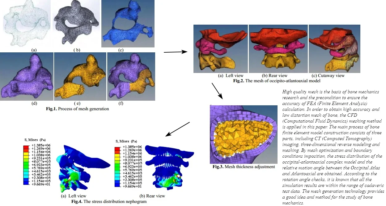
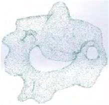
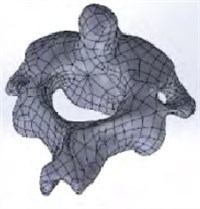
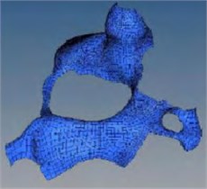
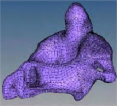
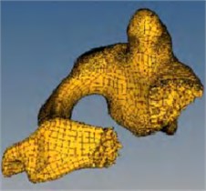
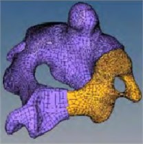
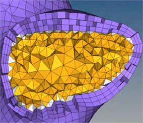
In order to highlight the significance of grid construction technology, the occipital-atlantoaxial complex model provided by a hospital was taken as the example object in the paper. Firstly, the CT (Computed Tomography) images need to be collected and the three-dimensional reconstruction of occipital-atlantoaxial complex model would be completed by Mimics medical image processing software. Secondly, the discrete point data can be obtained, as shown in Fig. 1(a). Thirdly, the point data of occipital-atlantoaxial complex model is imported into Solid Works, and the reverse modeling can be carried out. The three-dimensional solid model of bone is obtained, as shown in Fig. 1(b). The finite element pre-processing software Hyper Mesh is used to divide the three-dimensional model of the bone into CFD meshes. The geometric surface of the skeleton model is divided into two-dimensional quadrilateral meshes, as shown in Fig. 1(c). Referring to the two-dimensional quadrilateral mesh, multi layers of high-quality hexahedral elements are mapped into the model as cortical bone, as shown in Fig. 1(d). The rest of the model is divided into tetrahedral elements as cancellous bone, and the meshing of the skeletal model is completed, as shown in Fig. 1(e) and Fig. 1(f).
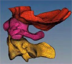
Using the same meshing method, the whole occipito-atlantoaxial complex model can be meshed, as shown in Fig. 2. It can be seen that the model retains the geometric characteristics of the skeleton. The mesh size of the skeleton contact surface is set as 0.5 mm, the mesh size of the rest is set as 1.5 mm, and the thickness of the cortical bone is set as 1 mm. It consists of three hexahedral elements with a size of 0.33 mm. The model consists of 103497 hexahedral units and 617784 tetrahedral units, including C3D20, C3D8, C3D6 and C3D4 type mesh.
2.3. Characteristics of generated mesh
CFD mesh generation method can greatly reduce the difficulty of partitioning and ensure the mesh quality within the model. The method generates two-dimensional quadrilateral meshes according to the geometric surface of the model, retains the geometric characteristics of the original model, and reduces the impact of simplification on the accuracy of the model. Because the object of two-dimensional quadrilateral mesh generation is a surface, mesh mapping is not necessary in surface generation. The complexity of the surface has little influence on the two-dimensional quadrilateral mesh generation, so it is less difficult to use the two-dimensional quadrilateral mesh to divide the geometric surface than the hexahedral element to divide the geometric entity. In addition, the method can adjust the thickness and number of hexahedral unit layers at any position to simulate the uneven thickness of cortical bone while keeping the geometric features of the model unchanged. By controlling the thickness, number and density of the outer hexahedron layer, the mesh quality and density of the skeleton model can be adjusted again. As shown in Fig. 3, the maximum thickness of the cortical bone of the upper joint in the grid model of the axis can be adjusted to 1.5 times the normal thickness.
Fig. 1Process of mesh generation
a)
b)
c)
d)
e)
f)
Fig. 2The mesh of occipito-atlantoaxial model
a) Left view
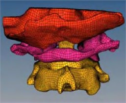
b) Rear view
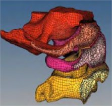
c) Cutaway view
Fig. 3Mesh thickness adjustment
3. Accuracy check of mesh model in finite element computing
3.1. Establishment of FEA model
The occipito-atlantoaxial is the most active joint in the spine. The mesh model of occipito-atlanto-pivot complex made by Hyper Mesh can be imported to the finite element software ABAQUS for static structure calculation. Pretreatment includes material parameter assignment, contact definition, load setting and constraint conditions. In the model, the ligaments are simulated by non-linear spring element, and the selection of spring loading points refers to the physiological and anatomical parts of the ligaments. Vertebral material was regarded as isotropic elastic material, and different material parameters were assigned to bone structure, cartilage and ligament respectively according to Ref [5-7], as shown in Table 1.
According to the physiological and structural characteristics of the occipital-atlantoaxial complex model, the contact of the model occurred in the following parts, including the atlanto-occipital joint, the atlantoaxial joint, the atlanto-odontoid joint and the cartilage at the ligament joint. Finally, twelve contact surfaces and six pairs of contact pairs can be obtained, which can be used to simulate the contact problems of each joint. The lower edge of the axis is fully constrained. In order to verify the accuracy of simulation results, the moment loading point is located in the middle and upper part of the occipital bone, and the loading point is coupled with bending moment of 15 N·m, just as the experimental conditions in Ref [8].
Table 1Model material properties
Skeleton parts | Poisson’s ratio | Modulus of elasticity / MPa |
Cancellous bone | 0.2 | 500 |
Cortical bone | 0.2 | 15000 |
Ligament | 0.19 | 86 |
3.2. Validation and analysis of results
The stress distribution of the occipital-atlantoaxial complex model and the relative motion angle between the Occipital Atlas (Symbol of C0-C1) and Atlantoaxial (Symbol of C1-C2) can be obtained by calculation. The relative motion angle is verified by experiments, as shown in Table 2. It can be seen that all the simulation results are within the range of cadaveric test data. There are significant differences in rotation angles under different conditions, and the maximum rotation angle occurs in the axial motion during C1-C2. Comparing the results of finite element model with the data of cadaveric experiment, it is proved that the finite element model made by CFD meshing method has high accuracy, can simulate the bone movement under complex physiological movement, and has a guiding role in clinical research of upper cervical spine.
Table 2Results validation
Movement type | Model components | Motion angle / degree | |
Experimental result | Simulation result | ||
Forward bending | C0-C1 | 10.8-17.2 | 15.33 |
C1-C2 | 9.8-16.2 | 14.28 | |
Axial rotation | C0-C1 | 1.0-10.5 | 9.56 |
C1-C2 | 24.2-46.4 | 35.15 | |
The stress distribution of the model is shown in the Fig. 4. It can be seen that the maximum stress is at the bottom of atlantoaxial, and there is a phenomenon of stress concentration.
3.3. Convergence analysis of mesh
In finite element simulation, different mesh sizes will have a greater impact on the accuracy of finite element calculation, the smaller the mesh size, the higher the accuracy of calculation; but too small mesh will greatly increase the number of elements and the time step of model solution, so it is necessary to consider the factors of simulation accuracy and calculation time cost in the modeling.
Fig. 4The stress distribution nephogram
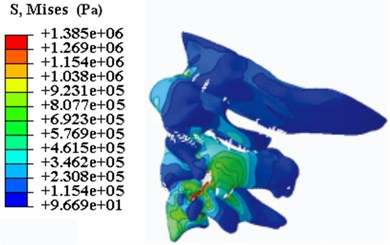
a) Left view
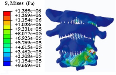
b) Rear view
Generally speaking, for the finite element method, the smaller the mesh size of the model, the closer the calculated result is to the experimental values. It can be found that with the decrease of mesh size, the calculation accuracy of the model increases gradually, but with the decrease of mesh size, the influence of the change of mesh size on the calculation accuracy decreases gradually. At the same time, as the mesh size decreases, the computing time of the model increases exponentially, this can greatly improve the computing time cost. The calculation results of the model are greatly influenced by the mesh size of the contact surface. The smaller mesh size of the contact surface can significantly improve the calculation accuracy of the model.
4. Conclusions
According to the characteristics of bone structure, the meshing technique of CFD fluid boundary layer is introduced into the meshing of bone biomechanics. The mesh model has a realistic appearance and simulates the physiological characteristics of the skeleton well. This method combines the advantages of tetrahedral mesh automatic generation and hexahedron mapping mesh generation methods, reduces the difficulty of meshing, improves the mesh quality of the model, and ensures the calculation accuracy of the model. At the same time, it is less affected by the curvature change of the geometric surface of the model, which retains the geometric characteristics of the original model and reduces the influence of simplification on the accuracy of the model. The research on bone meshing provides an effective way for complex bone reconstruction and lays a foundation for the biomechanical analysis of skeleton.
References
-
Grassi L., Isaksson H. Extracting accurate strain measurements in bone mechanics: A critical review of current methods. Journal of the Mechanical Behavior of Biomedical Materials, Vol. 50, Issue 8, 2015, p. 43-54.
-
Ling Z., Zhou L., Guo S. Equivalent circuit parameters calculation of induction motor by finite element analysis. IEEE Transactions on Magnetics, Vol. 50, Issue 2, 2014, p. 833-836.
-
Cuillière J. C., Francois V., Drouet J. M. Automatic mesh generation and transformation for topology optimization methods. Computer-Aided Design, Vol. 45, Issue 12, 2013, p. 1489-1506.
-
Puso M. A. A highly efficient enhanced assumed strain physically stabilized hexahedral element. International Journal for Numerical Methods in Engineering, Vol. 49, Issue 8, 2015, p. 1029-1064.
-
Yoganandan N., Kumaresan S., Pintar F. A. Biomechanics of the cervical spine Part 2. Cervical spine soft tissue responses and biomechanical modeling. Clinical Biomechanics, Vol. 16, Issue 1, 2001, p. 1-27.
-
Brolin K., Halldin P. Development of a finite element model of the upper cervical spine and a parameter study of ligament characteristics. Spine, Vol. 29, Issue 4, 2004, p. 376-385.
-
Zhang H., Bai J. Development and validation of a finite element model of the occipito-atlantoaxial complex under physiologic loads. Spine, Vol. 32, Issue 9, 2007, p. 968-974.
-
Sheng Y. Finite element analysis of occipital-atlantoaxial complex. Journal of Computer Simulation, Vol. 28, Issue 1, 2011, p. 268-272.
About this article

The paper is supported by the Youth Talent Innovation Project (BZXYQNLG201703).
