Abstract
The vibration reduction shall be considered as the most important purpose of dynamic performance optimization for gearbox, and some particular vibration is relevant to the modes of integrated system of gearbox. The dynamic performance influences the reliability of gearbox obviously, but it is difficult to be considered critically at the theoretical design phase. This paper proposes a kind of “Gearbox Dynamic Design Methodology” which can control the system vibration of the product at the theoretical design phase. The research investigates the relationship between the vibration and the system modes of gearbox by using multi-body dynamic simulation; and also discusses the method to regulate design parameters in order to optimize the mode characteristic (modal optimization). The methodology is summarized as per the discussions, and the effectiveness of vibration control is validated by multiple vibration experiments.
Highlights
- Analyze gearbox vibration by using multi-body dynamic simulation
- The serious vibration problem of gearbox can be caused by potential resonance
- The suitable design parameters of gear system are significant for avoiding resonance
- The gear geometry parameters should be considered to regulate the meshing frequency
- The proposed "Dynamic Design Methodology" is effective to control the vibration before prototype manufacturing
1. Introduction
The gearbox is a kind of common transmission component which is widely applied to the machinery systems, but it always has unexpected failures due to the complicated structure. The gearbox fault will not only causes plenty of unnecessary maintenance and repair works, but also make some limitations for the gear machinery applications. In general, the engineer who carries out the gearbox design is conditioned to pay more attentions to the static strength and fatigue life of the meshing gears and other parts (such as bearings), because they have basic performance requirements for their mechanical components. To understand the generation mechanism of the gearbox fault, Liang et al. [1] reviewed and discussed the relevant literatures which were focused on the dynamics based gearbox fault modeling. They summarized that the structure parameters or performances, such as gear tooth backlash and bending or shear deflection and so on would lead dynamic problems for the gearbox. The researchers prefer to focus on developing gearbox dynamic models with faults in order to understand the gear fault generation mechanism, and then developing effective fault detection and diagnosis methods; Tosun, Yildiz and Özkan [2] investigated the vibration of vehicle gearbox and carried out a modal analysis to examine the modes of the dominant path components, they validated the vibration was obviously relative to the whine noise of the gearbox; Weigang et al. [3] analyzed the fatigue strength of high speed train gearbox housings, they recognized that the serious vibration and impact during the high speed train running would cause fatigue cracks in the gearbox housings. The above-mentioned literatures indicate that serious vibrations during the gearbox running will cause harmful dynamic problems and faults. So this information implies that it is not enough to consider the regular performance only in the gearbox design.
The dynamic performance of the gearbox shall be regulated to control the harmful vibration, but it is difficult to be considered specifically at the theoretical design phase. Actually, some previous researches in recent decades have demonstrated that many factors could influence the dynamic performance of the gearbox. For example, Zuoqing and Xuezhi [4] supposed that the vibration and noise problems in gear transmission were relevant to gear meshing stiffness and damping; Fakher et al. [5] investigated the relationship between the gearbox vibration and the fluctuating load conditions, the experimental validation also confirmed that the time-varying load effects should be the main excitation for the dynamic performance responses of the gearbox; Jing et al. [6] considered the transmission error was an important reason for the instability in helical gears, they concluded that some basic gear meshing parameters, such as involute contact ratio, bearing supporting stiffness, mesh damping and backlash and so on could influence the dynamic transmission errors, and the vibration stability of the helical gear system was obviously involved in gear train transmission errors. Regarding to other factors besides gear meshing, Noroozi et al. [7] validated that the strength and stiffness of the foundation support structures were also relevant to gearbox vibration problems; Feki et al. [8] made a frequency analysis for two cases of a certain two-stage planetary gearbox in order to investigate vibration signals, the results demonstrated that the specific geometry and structure of gear train were relevant to dynamic responses. The conclusions imply that the dynamic performance of gearbox can be decided as long as to design the geometry of the gear train and the structure of the gearbox.
Presently, the common methodology for gearbox vibration reduction is to carry out the certain particular modification strategy on the basis of the specific gearbox vibration reasons. The actually applied technology might not be popular enough due to the different vibration mechanism. Qingzhong et al. [9] considered that the internal excitations (gear meshing frequency) of gear transmission system should be the source of gearbox housing vibration. They proposed an active vibration control method by applying an additional control load to decrease vibration, and the experiment results indicated that the method was obviously effective; Kurushin et al. [10] applied an elastic system for gear meshing to reduce the gear vibration by regulating the gear tooth meshing stiffness; Dogruer and Pirsoltan [11] proposed a kind of nonlinear active vibration control method by regulating the dynamic transmission errors, the effectiveness of their method was also validated by experiment. Actually, the above-mentioned vibration control methods shall be carried out on the basis of practical gearbox prototypes, the effectiveness of any vibration reduction modifications will be limited because the dynamic properties of gearbox have been decided once the design has been finished. Consequently, the “dynamic design methodology” for gear machineries, which can design the dynamic properties positively at the theoretical design phase, is very significant for decreasing the gearbox vibration effectively.
Hiremath and Venkataram [12] attempted to design a high speed gearbox with the consideration on dynamic requirement conditions; their works can demonstrate the concept that the dynamic performance of the gearbox can be designed. This paper will investigate the dynamic performance and vibration mechanism based on a case of over-vibration gearbox. The relevant analysis, such as modal analysis, time domain analysis and frequency analysis, will be carried out by flexible multi-body dynamic simulations. According to the theoretical results and experimental validations, the detailed procedure of “dynamic design methodology”, which is to regulate the designable geometry parameters in order to optimize the modal information and dynamic characteristics, will be proposed and defined as “modal optimization”.
2. Modeling
The investigation in this paper will be carried out on the basis of a case of wind turbine gearbox with seriously high vibration. The wind turbine gearbox was designed as typical transmission concept which had TWO planetary stages and ONE parallel axis stage, and the power requirement was 1.7 megawatt (MW). The others specific technical parameters are listed in Table 1.
Table 1Wind turbine gearbox parameters
Rated drive power | 1700 kW | Rotating direction | clockwise |
Rated generator rotating velocity | 1810 rpm | Rated input torque | 1015 kNm |
Generator rotating velocity range | 1030-2040 rpm | Total ratio | 113.125 |
2.1. Issue description
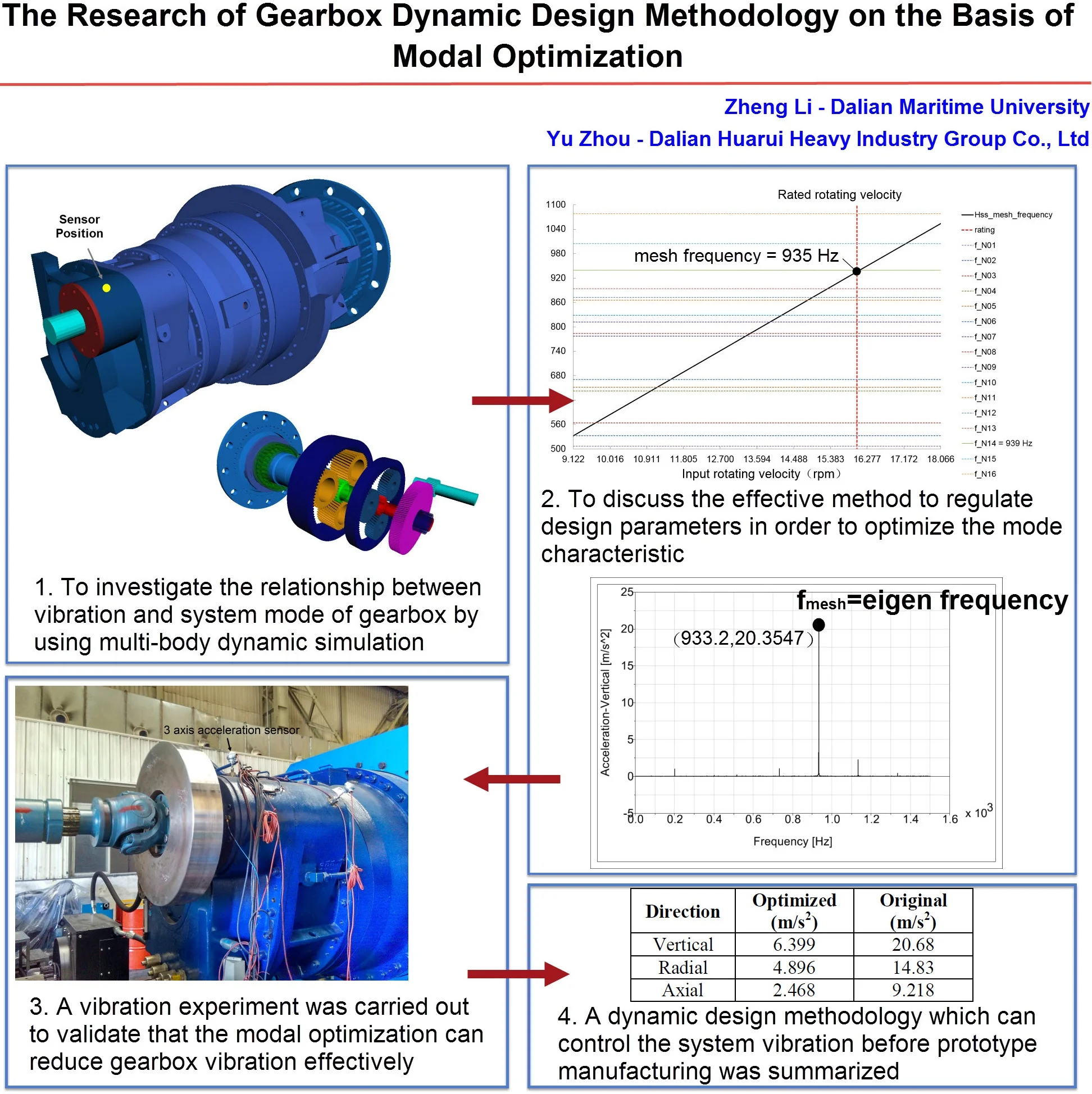
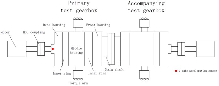
The gearbox was reported as having serious vibration at the high speed shaft (HSS) when it was operating under the rated rotating velocity and load conditions. The vibration test result (an acceleration sensor was set at the rear housing, Fig. 1) indicated that the highest vertical acceleration of the HSS was 20.68 m/s2 (Fig. 2). This phenomenon indicated that the terrible dynamic problem existed in the gearbox because the vibration of parallel axis stage exceeded the limitation seriously (7.5 m/s2, VDI 3834), so it should be solved otherwise the serious fault of the wind turbine could happen shortly.
Fig. 1Acceleration sensor position
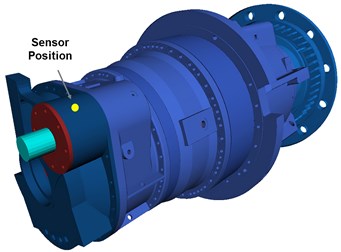
Fig. 2Original vibration test result
To investigate the vibration source and to research its generation mechanism, a flexible multi-body model of the faulted wind turbine gearbox will be built for a dynamic simulation. The simulated model will be used to analyze the dynamic performance of the gearbox transmission system in order to find the most significant issues for the HSS vibration generation. After that, a reliable optimizing modification scheme will be proposed according to the simulation results, which were derived from the modeling, and relevant discussions.
2.2. Multi-body dynamic model
The software tool was used for modeling is SIMPACK, it is a kind of professional software for solving mechanical dynamic problems. Modeling assignments should consider following 4 segments: components system, transmission system, boundary conditions and load conditions:
– Components system: all of the rotating components and housing parts of the gearbox shall be considered; mass and rotary inertia of each component in the model shall be defined exactly; the elastic characteristic (stiffness matrix) of all the shafts shall be considered, the rear housing and its cap shall also be considered as flexible components because they are relevant to vibration responses of parallel axis stage directly.
– Transmission system: all the meshing gears in the gearbox drive train (two planetary stages and one parallel axis stage) shall be defined in the model, the gear meshing stiffness and damping shall be considered for the analysis.
– Boundary conditions: the gearbox modeling shall consider the stiffness of the connections between certain two components adequately, such as interference fit, spline connection, elastic support to the gearbox torque arm and coupling etc. The 6-DOF stiffness matrix of all bearings (especially the HSS bearing) shall be considered in order to calculate the vibration responses of HSS as accurately as possible.
– Load conditions: input and output torque and rotating velocity shall be defined as rated load condition (output torque and rotating velocity can be calculated according to the gearbox ratio).
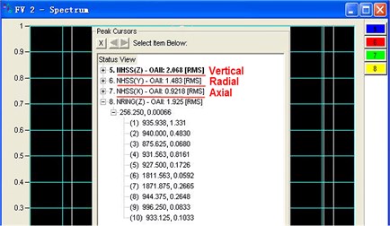
The completed simulation model with above-mentioned considerations and requirements is illustrated by Fig. 3. The specific analysis and discussions are presented in subsequent sections.
The purpose of the multi-body dynamic analysis is to calculate the vibration responses on particular component by solving the coupled dynamic equation set. The analytical solutions regarding the vibration performance of the gearbox drive train shall be considered as the predictions to the gearbox prototype vibration. Theoretically, with the consideration of the relevant boundary conditions such as mass; rotating inertia; damping; elastic matrix and so on, the dynamic equation of the gearbox drive train can be written by the following equations [13]:
where: is the generalized displacement vector; is the generalized mass matrix; is the generalized damping matrix; is the generalized stiffness matrix.
For the theoretical derivation, the designation of symbols in the formula shall be defined as per following nomenclature in Table 3.
Fig. 3Multi-body dynamic modeling of wind turbine gearbox
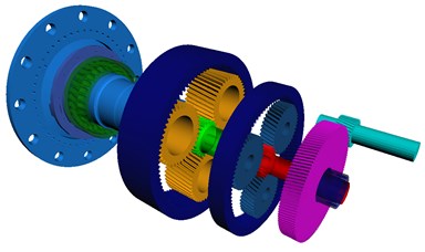
Fig. 4Gearbox transmission concept
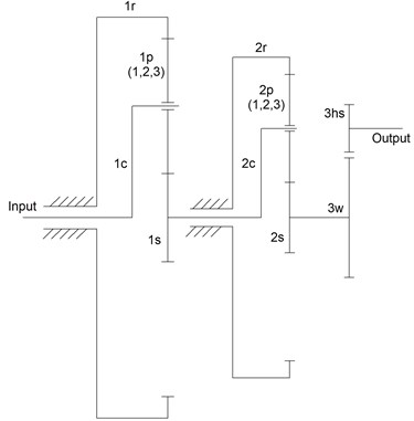
Table 2Nomenclature of gearbox components
Input: Power input, low speed shaft |
Output: Power output, high speed shaft |
1c/2c: stage 1/2 carrier |
1r/2r: stage 1/2 ring gear |
1s/2s: stage 1/2 sun gear shaft |
1p (1, 2, 3): stage 1 planet gears (3 gears) |
2p (1, 2, 3): stage 2 planet gears (3 gears) |
3w: stage 3 wheel gear |
3hs: stage 3 high speed gear (pinion gear) |
Table 3Nomenclature of symbols in formulas
Subscript | Signification | Values |
, , , | c-carrier, p-planet, s-sun, r-ring The number of planet gear in a stage The number of stage | – 1, 2, 3 1, 2, 3 |
Items | Signification | Values |
Angular displacement of the component in stage | 1, 2, 3 , , , , , , , | |
Rotating radius of planet gears in stage Base radius of gear components in stage | 1, 2, 3 , , , , , , | |
// // // | Meshing error/stiffness/damping between sun gear and planet gear; ring gear and planet gear in stage ; wheel gear and high speed gear in stage 3; | 1, 2 1, 2, 3 |
/ / | Coupling stiffness/damping between stage 1 sun gear and stage 2 carrier; stage 2 sun gear and stage 3 wheel gear; | – |
/ | Input/output torque | – |
The rotary inertia of component in stage 1 The rotary inertia of component in stage 2 | , , , , , , , | |
/ / | Working pressure angles of sun gear and ring gear in stage 1 and 2 | – |
The equivalent rotary inertia of stage 1 carrier The equivalent rotary inertia of stage 2 carrier | ||
Mass of planet gears of stage 1 Mass of planet gears of stage 1 | – |
The drive train of the gearbox is a typical multi-body system, so the factors in the formula which can describe the dynamic transmission characters shall be generalized in a matrix or by vectors with the consideration of the coupled components in such an integrated system. According to the listed nomenclatures, the dynamic equation can be expanded as follows.
The generalized displacement vectors are:
The generalized mass matrix is:
The generalized damping matrix is:
The generalized stiffness matrix is:
is generalized force vectors, the matrix is:
According to the above expanded factors, an undamped free vibration equation can be derived from the dynamic equation, so it is considered as the theoretical basis for a modal analysis of a multi-body system of wind turbine gearbox:
where: is the eigen value of mode ; is the mode shape of mode .
The particular solutions of above equation are results of modal analysis, which includes the eigen values and mode shapes of the system modes. All of the above analytical procedure will be carried out using the Simpack solver, and the results and relevant discussions will be mentioned in the next sections.
3. Simulations on original model
To understand the derivation of serious vibration of the faulted gearbox, the primary assignment is to calculate the vibration response of the sensor position on the rear housing (see Fig. 1), and the analysis can be carried out by a multi-body dynamic simulation for the gearbox model with original design parameters (original model). The theoretical simulation results shall be similar to the experimental data in order to guarantee the reliability of the simulation model, and the following studies on the basis of this model shall make sense for the research. The following figures illustrate the original results of directional acceleration responses of the sensor position on the basis of a frequency domain analysis:
Figs. 5-7 all have significant peak values of directional acceleration. The phenomenon indicates that the maximum acceleration response will appear on a certain exciting frequency. It means there will be additional vibration load due to serious acceleration response (according to the Newton’s second law). The load shall be controlled effectively otherwise it will cause harmful fatigue problems to the drive train. Particularly, Fig. 5 illustrates the peak vertical acceleration is 20.355 m/s2, and the corresponding exciting frequency is 933.2 Hz; the peak radial and axial accelerations are 10.207 m/s2 (Fig. 6) and 8.192 m/s2 (Fig. 7), and the exciting frequencies are same as the vertical. Obviously, all of the peak directional accelerations exceed the limitation (7.5 m/s2, VDI 3834), and the vertical acceleration response is the most serious of all; the situation consists with the reality absolutely. Other radial and axial acceleration values which are only less than peak values can be ignored because such acceleration responses do not exceed the limitation. Consequently, the significant exciting frequency which causes peak directional accelerations is 933.2 Hz. Table 4 lists the comparison between simulation results and experimental data (see Fig. 2), the data indicate that the simulation results are almost similar to the experimental data. The obvious error in the radial direction is believed to be caused by the boundary conditions disagreement between simulation and experiment; the model is still reliable enough because the simulation results consist with the experimental data basically.
Fig. 5Vertical acceleration (original)
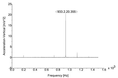
Fig. 6Radial acceleration (original)
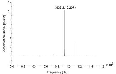
Fig. 7Axial acceleration (original)
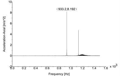
Table 4Original comparison (sim./Exp.)
Direction | Simulation (m/s2) | Experiment (m/s2) |
Vertical | 20.355 | 20.68 |
Radial | 10.207 | 14.83 |
Axial | 8.192 | 9.218 |
Peak vibration frequency: 933.2 Hz | ||
Generally speaking, the exciting frequency is not permitted to approach any eigen values of natural frequencies for avoiding resonance risk. This question can be validated by carrying out the modal analysis on the gearbox drive train. Furthermore, the gear meshing shall be the most significant excitation to the gearbox, and the mesh frequency can be calculated according to the numbers of teeth and rotating velocities of the gear pair. For the investigation in this paper, it is necessary to pay more attention to the mesh frequency of parallel axis gear stage because the excitation shall be the main reason of the serious vibration on rear housing. The mesh frequency can be calculated by the following equation:
where: is the mesh frequency; , are rotating velocities of each gear in gear pair (rpm); , are the numbers of teeth of each gear in gear pair.
The numbers of teeth and rotating velocities are the basic parameters for gearbox design. In this research, the primary parameter is 127/31, and the module is 7 mm; the mesh frequencies with different input rotating velocities (see Table 1) are listed in Table 5.
Table 5Parallel axis gear stage mesh frequency
Work condition | HSS rotating velocity (rpm) | Input rotating velocity (rpm) | Mesh frequency (Hz) |
Cut in | 1030 | 9.122 | 532.17 |
Rated | 1810 | 16.029 | 935.17 |
Cut out | 2040 | 18.066 | 1054 |
Fig. 8Original eigen frequencies
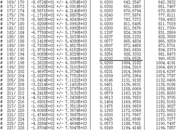
Fig. 9Campbell diagram (original model)
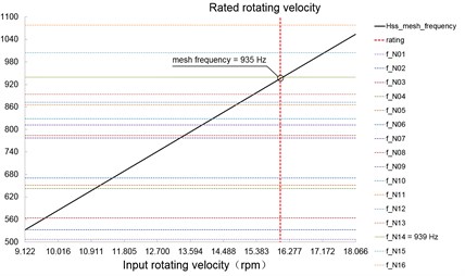
Table 5 indicates that the mesh frequency of HSS in the rated rotating velocity is 935.17 Hz, and it is highly approaching 933.2 Hz. This situation implies that the maximum vibrations on the rear housing shall be the response to the excitation of HSS mesh frequency. To research the relationship between the exciting frequency and natural frequency, the modal analysis on the gearbox drive train shall be carried out to obtain the eigen values of the natural frequencies. Fig. 8 illustrates the eigen frequencies, it indicates a mode with the natural frequency 939 Hz, and the eigen frequency is highly approaching the exciting frequency. Fig. 9 displays a Campbell diagram which was derived from the data in Table 5 and Fig. 8, it illustrates that the line which states the exciting frequency (Hss_mesh_frequency) intersects with the line which states the natural frequency (f_N14); the point of intersection locates very close to the rated input rotating velocity. All of the phenomena imply that the parallel axis gear stage has potential resonance, and the particular excitation shall be the HSS gear meshing on the rated work condition. In other words, the maximum vibration appears when the drive train achieves to the rated rotating velocity. This deduction absolutely consists with the problem which is performed by a vibration test.
The above analysis results demonstrated that the faulted vibration of wind turbine gearbox had been mainly caused by potential resonance. The reason of resonance is that the HSS gear meshing exciting frequency approaches the eigen frequency of a certain mode. Consequently, it should be effective to create a significant difference between the exciting frequency and eigen frequency of a particular mode for vibration reduction, but the modal information is difficult to be modified because it has been decided absolutely in the gearbox drive train design. To consider this situation, it is possible to create such a frequency difference mentioned above by choosing suitable numbers of teeth, and the best scheme shall be decided with the consideration of eigen frequencies of drive train. This “modal optimization” theory can be defined as a new kind of “dynamic design methodology”, and the effectiveness regarding vibration control will be validated.
4. Simulations on optimized model
According to Eq. (3), the HSS gear meshing frequency can be regulated by changing the numbers of teeth of the gear pair (the rotating velocities are steady), and other gear geometry parameters shall also be modified. Basically, any modification shall guarantee that the ratio of modified parallel axis gear stage should be similar to the original model; and the actual tooth strength should satisfy essential strength requirements. Furthermore, the most important consideration is that the modified HSS meshing frequency should locate between the eigen frequencies of certain two adjoining modes, and there are sufficient differences between HSS meshing frequency and eigen frequencies. For the expected modification, the original gear parameters of HSS gear pair can be regulated to meet the frequency requirements. The optimized gear parameters according to the original model are listed in Table 6.
After optimization, the current HSS meshing frequencies with different input rotating velocities are listed in Table 7.
Table 6Gear parameters comparisons between original and optimized model
Parameters | Original model | Optimized model | ||
Module | 7 mm | 9 mm | ||
The number of teeth | 31 | 127 | 22 | 90 |
Shift factors | 0.2498 | –0.2346 | 0.3361 | 0.1062 |
Helix angle | ±9° | ±25° | ||
Table 7Parallel axis gear stage mesh frequency
Work condition | HSS rotating velocity (rpm) | Input rotating velocity (rpm) | Mesh frequency (Hz) |
Cut in | 1030 | 9.135 | 377.67 |
Rated | 1810 | 16.052 | 663.67 |
Cut out | 2040 | 18.092 | 748 |
Table 7 indicates the optimized HSS mesh frequency (on rated work condition) is reduced to 663.7 Hz. Fig. 10 indicates that the two eigen frequencies which are similar to optimized HSS meshing frequency (663.7 Hz) are 651.2 Hz and 670.7 Hz, the influence of potential resonance shall be decreased significantly because there are sufficient differences between the exciting frequency and eigen frequencies. The Campbell diagram illustrates the relationships between the optimized HSS meshing frequency and all the natural frequencies; it is clear that the points of intersection between the exciting frequency line and the eigen frequency lines are far away from the rated rotating velocity (the black points in Fig. 11). The phenomenon implies the potential resonance risk can be avoided successfully when the drive train is operating at the rated rotating velocity, and consequently the vibration of the drive train shall be decreased effectively by the “modal optimization” methodology. The deduction will be demonstrated and validated by the multi-body dynamic simulation based on the optimized model.
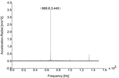
Figs. 12-14 illustrate the optimized results of directional acceleration responses of the sensor position; the boundary conditions and the analysis procedure are same as the frequency domain analysis on the basis of original model. The resulting figures present that the peak directional acceleration responses and their corresponding excitations are changed obviously. First, the significant exciting frequencies which are relative to peak directional accelerations are changed from 933.2 Hz to 666.6 Hz due to the modification of the numbers of teeth. The optimal exciting frequency is different from eigen frequencies significantly in the case. Second, Table 8 lists the peak values of directional acceleration of the original model and the optimized model; the comparison indicates that the vibration of the drive train has been decreased significantly: the optimal peak vertical acceleration was decreased to 5.563 m/s2 (Fig. 12), it was reduced by 72.67 %; the optimal peak radial and axial accelerations were 3.445 m/s2 (Fig. 13) and 2.481 m/s2 (Fig. 14), they were reduced by 66.3 % and 69.7 % individually. The principle is that the potential resonance which exists in HSS is avoided by regulating the numbers of teeth of HSS gear pair. Other radial and axial acceleration values which are only less than peak values can also be ignored as the original results. After optimization, the vibration response in each direction has been regulated to the acceptable value which was less than limitation (7.5 m/s2, VDI 3834). This situation indicates that the vibration load which is derived from directional acceleration response is controlled effectively, and the fatigue life and reliability of the HSS gears are improved significantly. The results are consistent with the situations which are displayed in the Campbell diagram of optimized model (Fig. 11), and they imply that the gear geometry parameters are relative to the vibrations of drive train.
Fig. 10Optimized eigen frequencies
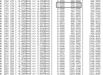
Fig. 11Campbell diagram (optimized model)
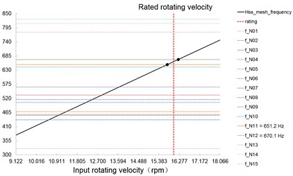
Fig. 12Vertical acceleration (optimized)
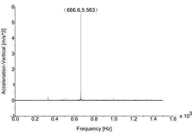
Fig. 13Radial acceleration (optimized)
The simulation results from the optimized model have demonstrated that the vibrations can be controlled by regulating gear meshing frequency; the numbers of teeth shall be defined critically to decrease the influence of potential resonance. Actually, the potential resonance shall be avoided as much as possible in order to optimize the vibration performance of gearbox drive train. Furthermore, the results of modal analysis have indicated that the eigen frequencies of gearbox drive train would not be affected significantly by changing the gear geometry parameters, but the exciting frequency could be regulated conveniently by deciding the numbers of teeth and rotating velocities. Consequently, the gear geometry parameters can influence the vibration performance due to the determinations of meshing frequency. It will be useful for avoiding potential resonance to design the suitable gear geometry parameters with the consideration of modal optimization. This conclusion is the most important theory of dynamic design methodology, and the effectiveness can be validated by the experimental method.
Fig. 14Axial acceleration (optimized)
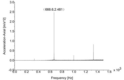
Table 8Simulation results comparison
Direction | Optimized (m/s2) | Original (m/s2) |
Vertical | 5.563 | 20.3547 |
Radial | 3.445 | 10.2069 |
Axial | 2.481 | 8.1921 |
5. Experimental validation
A vibration test was carried out on a two megawatt back-to-back gearbox test rig. The optimized wheel gear and high-speed shaft gear are manufactured to be assembled. It is necessary to be noticed that other geometry parameters of the modified gears, such as helix angle and shift factors, shall also be updated to guarantee the central distance of modified gear pair is consistent with the original design. It is very important for the interchangeability of the high-speed stage. The main purpose of vibration test is to examine the acceleration level in the position which was displayed in Fig. 1; consequently a 3-axis acceleration sensor was installed on the sensor position to capture the acceleration data. The vibration test was repeated five times to obtain the maximum vertical acceleration value (the vibration acceleration is concerned significantly) for evaluation. The Fig. 15 indicates the general assembly of the test rig.
Fig. 15Two megawatt back-to-back test rig for vibration test
The original vibration test result displayed in Fig. 2 also derives from identical test system and strategy. The test results indicated that there were serious vibrations on the rear housing due to the potential resonance in the high-speed stage. After necessary modifications with the consideration of modal optimization, the potential resonance influence shall be avoided, and the vibrations of the optimized gearbox are decreased significantly.
Fig. 17 displays the results of vibration test for the optimized gearbox with the maximum vertical acceleration value among multiple experiments (the test was repeated five times). The results were obtained from the third test, and they were considered as the most significant experimental results of the optimized gearbox. Table 9 compares the experimental results of the optimized gearbox with the vibration test results of the original gearbox; Table 10 contains comparisons between the experimental results of the optimized gearbox and the simulation results of the optimized model. The data showed in the figure and tables indicate that the vibrations of the faulted gearbox are all reduced to the levels under the limitation. The phenomenon validates the effectiveness and significance of modal optimization; it means that some basic vibration responses, which are determined by modal information of the gear drive train, can be controlled in the design process with the consideration of modal optimization. Consequently, the methodology, which is applied to design the gear geometry parameters for the purpose of controlling the potential resonance influence on the drive train, is defined as “Dynamic Design Methodology” of the gearbox.
Fig. 16Vibration test rig
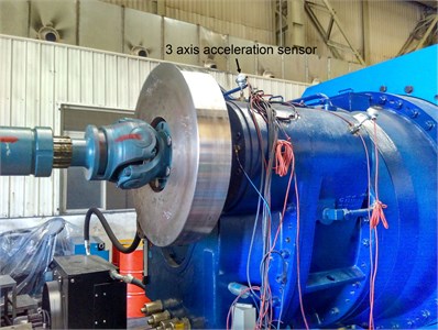
Fig. 17Optimized vibration test result
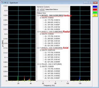
Table 9Experimental results comparison
Direction | Optimized (m/s2) | Original (m/s2) |
Vertical | 6.399 | 20.68 |
Radial | 4.896 | 14.83 |
Axial | 2.468 | 9.218 |
Table 10Optimized comparison (sim./Exp.)
Direction | Simulation (m/s2) | Experiment (m/s2) |
Vertical | 5.563 | 6.399 |
Radial | 3.445 | 4.896 |
Axial | 2.481 | 2.468 |
6. Conclusions
The paper describes a case study to investigate the methodology of gearbox vibration reduction. The relevant discussions demonstrated that the production mechanism of the faulted gearbox vibration was the potential resonance on the rated work condition. According to the results of milt-body dynamic simulation, the recommended solution for avoiding the resonance influence is to modify the basic gear parameters (especially the numbers of teeth and modules) to regulate risky exciting frequency. The effectiveness of such “modal optimization” strategy for gearbox vibration reduction was validated by the experimental method. Basically, the proposed solution for the faulted gearbox in the case study indicates that the basic gear parameters shall be decided with the consideration of modal information of the drive train. The specific processes for determining basic gear parameters can be defined as a kind of “Gearbox Dynamic Design Methodology”, it is practicable to be carried out at the theoretical design phase of gearbox.
This paper is focused on the proposed “Gearbox Dynamic Design Methodology”, it is a kind of the optimal design method in nature. The particular processes shall include the following steps:
1) To design primary gear geometry parameters and gearbox structure on the basis of essential strength requirements as a regular gearbox design procedure.
2) To calculate the exciting frequencies of each stage according to the range of working rotating velocities and transmission ratios.
3) To carry out a multi-body dynamic modal analysis for the integrated drive train of the gearbox, a Campbell diagram is made to compare the eigen frequencies and exciting frequency in order to evaluate the risk of potential resonance.
4) To regulate the numbers of teeth and module of all gear pairs in the drive train for the modal optimization (the transmission ratios should not be changed). The expected status is that the exciting frequencies of each stage will not be accordant to any eigen frequencies. It may be difficult to achieve the expected status perfectly, but it is still recommended to keep the rated exciting frequency away from the eigen frequencies significantly.
Once the gearbox prototype has serious vibration problem after manufacturing, it will make high costs for maintenance or modification. The vibration problem may not be solved effectively because the passive solutions for vibration problems will have many limitations due to the fixed structure. Generally speaking, the regular gearbox design strategy can hardly consider the vibration performance of ongoing design scheme, but the proposed “Gearbox Dynamic Design Methodology” can help designers to consider or predict the vibration performance of the gearbox at the theoretical design phase. If the gearbox products can be designed with the methodology, the risk of potential resonance can be avoided to limit the basic vibrations determined by the system mode, and the integrated vibration performance of the drive train will be controlled effectively.
References
-
Liang X., Zuo M. J., Feng Z. Dynamic modeling of gearbox faults: a review. Mechanical Systems and Signal Processing, Vol. 98, 2018, p. 852-876.
-
Tosun M., Yildiz M., Özkan A. Investigation and refinement of gearbox whine noise. Applied Acoustics, Vol. 130, 2018, p. 305-311.
-
Weigang H., Zhiming L., Dekun L., et al. fatigue failure analysis of high speed train gearbox housings. Engineering Failure Analysis, Vol. 73, 2017, p. 57-71.
-
Zuoqing Z., Xuezhi Z. Study about the effect of meshing stiffness and meshing damping on gear vibration. Machine Tool and Hydraulics, Vol. 38, Issue 5, 2010, p. 32-34.
-
Fakher C., Walter B., Radoslaw Z., et al. Gearbox vibration signal amplitude and frequency modulation. Shock and Vibration, Vol. 19, Issue 4, 2012, p. 635-652.
-
Jing W., Pan G., Xinglong H., Etc Effects of dynamic transmission errors and vibration stability in helical gears. Mechanical Science and Technology, Vol. 28, Issue 6, 2014, p. 2253-2262.
-
Noroozi S., Rahman A. G. A., Dupac M., et al. Condition monitoring and diagnostics of an extruder motor and its gearbox vibration problem. Insight: Non-Destructive Testing and Condition Monitoring, Vol. 58, Issue 2, 2016, p. 101-107.
-
Feki N., Karray M., Khabou M. T., et al. Frequency analysis of a two-stage planetary gearbox using two different methodologies. Comptes Rendus Mecanique, Vol. 345, Issue 12, 2017, p. 832-843.
-
Qingzhong D., Yinong L., Feng Z. Adaptive filter algorithm for active vibration control of gear transmission, Journal of Mechanical Engineering, Vol. 49, Issue 15, 2013, p. 74-81.
-
Kurushin M. I., Balyakin V. B., Kurushin S. A. Methods of vibration control in elastic systems with gears. Procedia Engineering, Vol. 106, 2015, p. 192-201.
-
Dogruer C. U., Pirsoltan A. K. Active vibration control of a single-stage spur gearbox. Mechanical Systems and Signal Processing, Vol. 85, 2017, p. 429-444.
-
Hiremath V., Venkataram N. Vibration characteristics of a high speed gearbox through dynamic analysis. Materials Today: Proceedings, Vol. 4, Issue 10, 2017, p. 10935-10943.
-
Jungang W., Yong W., Zhipu H. Establishment of mathematic model and study of vibration modes for multi-stage planetary gear train of wind turbine gearboxes. Journal of Sichuan University (Engineering Science Edition), Vol. 45, Issue 3, 2013, p. 189-196.
About this article

