Abstract
TBM cutterhead works in complex working conditions, which endures the reverse impact forces of rock breakage, resulting in parts abnormal failure. Hence, the study of the system inherent characteristics is the basis for cutterhead dynamic design. Based on the established vibration model of a TBM split-cutterhead system, the modal method is used in the dynamic model and the natural frequency sensitivity expressions to system parameters are deduced. Then a cutterhead system of a water conservancy project in China is taking as an example, the natural frequency sensitivity with respect to the cutterhead support stiffness and mass parameters is obtained, and the influence of the two parameters on natural characteristics is analyzed. The results show that, the 10th-20th order natural frequencies are mainly affected by the cutterhead support stiffness and mass parameters, and the 9th-11th order frequencies are mainly influenced by cutterhead moment of inertia. Besides, with the change of stiffness and mass parameters, the cutterhead system natural frequency curves cut across each other and there are also many inflection points in the sensitivity curves, then the modal jumping occurs near these points. The parameter sensitive points were obtained from the results, which can provide reference for TBM cutterhead system parameters matching.
Highlights
- Natural frequency sensitivity expressions to a TBM cutterhead system are deduced based on modal method.
- The influence of the stiffness and mass parameters on natural characteristics is analyzed.
- Many parameter sensitive points are obtained from the results to provide reference for parameters matching.
1. Introduction
Tunnel Boring Machine (TBM) is a kind of advanced engineering equipment used in various tunnels, which is widely applied to the urban subways, river-crossing or sea-crossing tunnels and national defense tunnel excavation. Compared with other excavation methods, TBM has the advantages of fast tunneling speed, environmental protection and high efficiency. Cutterhead system is the core component of rock breaking, which endures the reverse impact forces of rock breakage duo to the complicated geological conditions. As a result, the structural vibration and various components failure are caused by the impact forces, such as the cracking of cutterhead panel, main bearing failure and cutter seat cracks [1, 2]. Therefore, the cutterhead strength, system dynamic performance and fatigue life requirements are very high, and it is necessary to analyze the system vibration characteristics in the structural design stage. The natural characteristic is the research foundation of vibration analysis, and analysis of different parameters on the natural frequencies and sensitivity, can provide a basis for system parameters matching.
Scholars have done a lot of research on the TBM cutterhead system design, and encouraging achievements have been obtained. As early as 1980s around in overseas, Hopkins [3] and Samuel [4] et al. studied the variation rule of rock breaking loads at the tunneling field and laboratory, through the force sensors installed on the cutter shaft. A novel method named Rock Joint Rate (RJR) for predicting the penetration rate (PR) of TBM in hard rocks was proposed and huge amounts of engineering data was utilized to validate the proposed model [5]. In recent years, Jamal Rostami, an international well-known TBM expert, presented many cutterhead design and performance prediction models for hard rock TBM combined with some engineering cases, which can provide reference for cutterhead structural design and performance analysis [6, 7]. In domestic, some key technologies involved in the TBM cutterhead design were presented and the further research issues of cutterhead design were proposed by Liu et al. [8]. A free-face-assisted rock breaking method was proposed for improving the rock breaking efficiency, and then a multi-stage TBM cutterhead structure was designed and series of proof-of-concept tests were carried out to validate the proposed method [9]. Xia, Tan et al. studied the rock breaking characteristics and impact loads of different cutters, using the discrete element method, finite element method and experimental method [10-12]. Besides, some scholars studied the rock cutting forces, disc cutter wear performance and rock breaking efficiency with different kinds of cutters by the means of simulation and rotary cutting test [13, 14]. Similarly, Han, Xia et al. established a TBM excavation finite element model to investigate the dynamic responses of cutterhead loads, and the simulation results were validated by a tunneling test [15]. Also, the cutterhead loads and tunneling parameter characteristics were directly studied using the theoretical derivation and numerical methods, which can provide guidance for TBM construction parameters matching [16, 17]. Moreover, Sun, Huo et al. has been done a lot of research work in the aspects of TBM cutterhead system vibration characteristics, tunneling field test, electromechanical coupling vibration model as well as the structural performance evaluation, and some useful results were achieved, which also can provide reference for TBM cutterhead structural anti-vibration design and parameters matching [18-21].
As mentioned above, scholars have studied the TBM cutter rock breaking characteristics, cutterhead loads and system vibration by the means of field test, numerical simulation and theoretical derivation, and some instructive conclusions were obtained. However, the TBM cutterhead system natural characteristics, influence of different parameters on natural frequencies and sensitivity have been seldom involved previously. Accordingly, in this paper, the parameter sensitivity expressions of cutterhead system natural frequency are deduced by using the modal method, based on the established dynamic model of TBM cutterhead system. Then a TBM cutterhead of a water tunnel project in northwest Liaoning province is taken as an example, the influence of cutterhead support stiffness and mass parameters on the system natural frequencies and sensitivity is analyzed, to lay foundation for the cutterhead system dynamic design and parameters matching.
2. Multi-degree of freedom coupling dynamic model about TBM cutterhead system
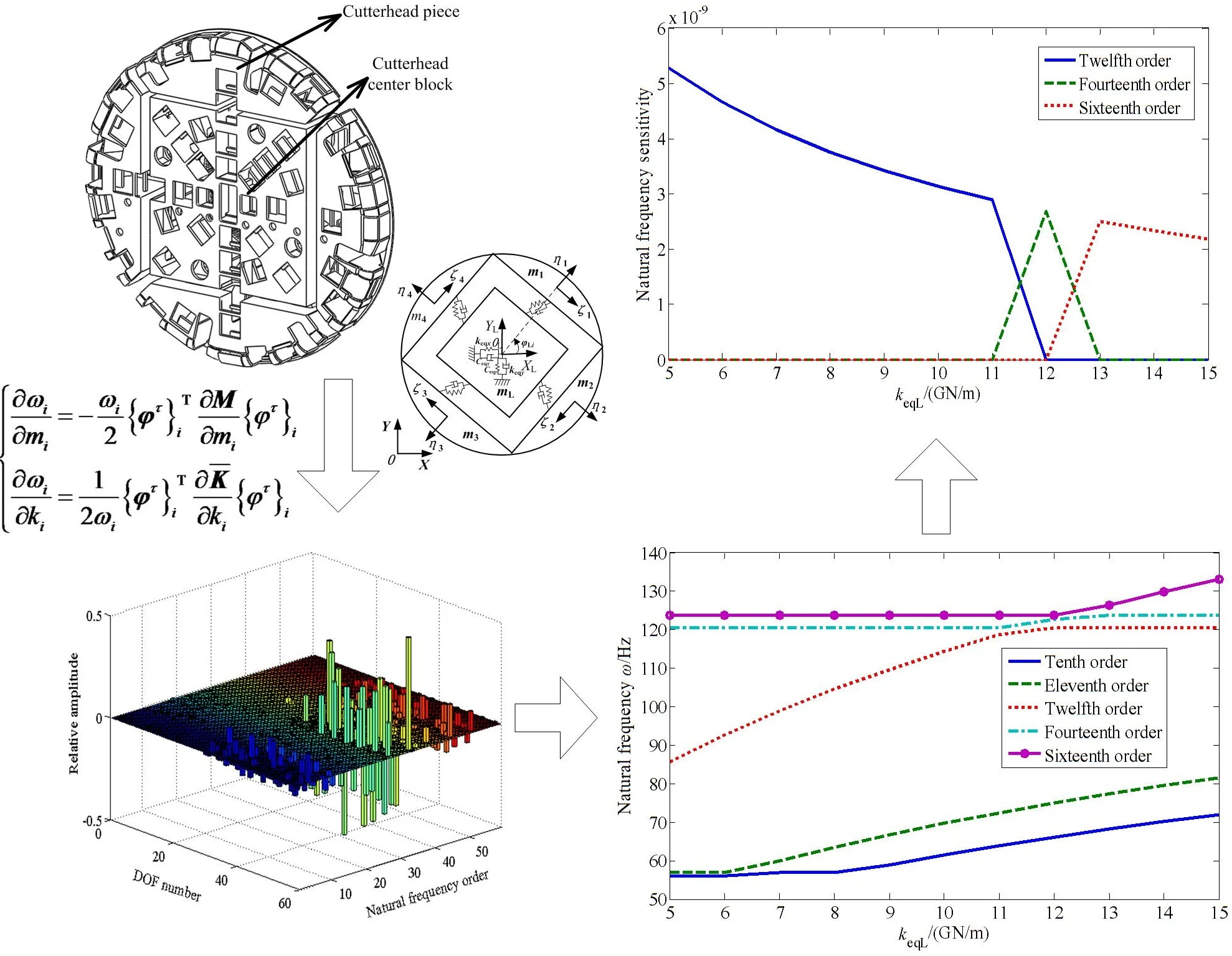
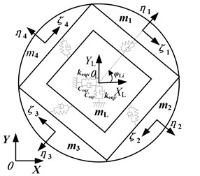
The rotary torque is transmitted to the pinions by multiple motors through the respective planetary gear reducers when the TBM tunnels. Then an inner ring gear fixed with the cutterhead flange is derived by the pinions, so as to drive the cutterhead. For a cutterhead with diameter over 8m, the cutterhead plate body is generally made up of several pieces, and each piece is connected with the center block by welding and bolts. The typical split-cutterhead structure with medium square is shown in Fig. 1. A multi-degree of freedom coupling vibration model of a split-cutterhead system has been established, based on the lumped mass method, with the coupling vibration model of cutterhead piece and center block showing in Fig. 2 [18]. For the other structural vibration models, see reference [18], and the detailed dynamics differential equations are also presented in this literature.
3. Sensitivity analysis method for cutterhead system natural frequencies
Modification of physical parameters method is a useful tool for system vibration optimization. Physical parameters can be modified in a targeted way, and the system can obtain predetermined vibration characteristics with this method. Therefore, it is necessary to study the natural frequencies variation with physical parameters, and to explore the natural frequencies sensitivity to the mass, stiffness and other parameters changing. Mathematically, sensitivity is a derivative. Physically, it reflects the modal parameters sensitivity to a system inertial or elastic element. In this paper, the modal method is used to analyze the natural frequencies sensitivity of TBM cutterhead system [22], and the mathematical derivation process of the actual cutterhead system is presented as follows.
Fig. 1Split-cutterhead structure
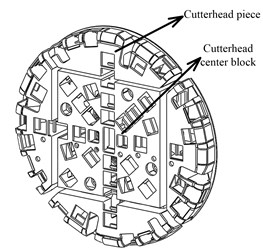
Fig. 2Coupling vibration model of cutterhead piece and center block
For an undamped free vibration equation, the characteristic equation is:
It is supposed that the symmetric matrix , then Eqs. (1) can be expressed as:
where is the cutterhead system average stiffness matrix, with the expression showing in Appendix, is the cutterhead system mass matrix, which is a diagonal matrix, shown in reference [18], , are the system th eigenvalue and eigenvector, respectively, and:
and , are the vibration components of cutterhead piece, cutterhead center block, inner ring gear, support shield body and the pinions, respectively.
Then Eqs. (2) is multiplied by the vector on the left, and Eqs. (3) can be expressed as:
Eqs. (3) is took the partial derivative of physical parameter , and the expression can be obtained as follows:
Since the matrix is a symmetric matrix, the Eqs. (2) can be transposed as follows:
Then Eqs. (2) and Eqs. (5) are substituted into Eqs. (4):
A normalized mode vector is introduced, which is satisfied the following expression:
Then Eqs. (7) is substituted into Eqs. (6), it can be obtained:
The above expression is the sensitivity of the system th eigenvalue to physical parameter .
In addition, since the cutterhead system average stiffness matrix is unrelated to the mass parameter , and the mass matrix is also unrelated to the stiffness parameter , that is:
Eqs. (9) is substituted into Eqs. (8), and the sensitivity expressions of the th eigenvalue to the mass parameter and stiffness parameter can be described as follows, respectively:
Besides, the relationship between the natural frequency and eigenvalue is , so the sensitivity expressions of natural frequency can be expressed:
4. Case study
The cutterhead system mass matrix and average stiffness matrix are substituted into Eqs. (11), then the system natural frequencies sensitivity to the mass and stiffness parameters can be obtained. In view of the paper length restriction, this paper mainly studies the influence of actual cutterhead support stiffness and mass parameters on natural characteristics and sensitivity, and the influence analysis of other parameters are similar.
4.1. Overview of an actual cutterhead system
This case study object is based on a water tunnel project in northwest Liaoning province, China. The tunnel net section diameter is 7.51 m, and the TBM excavation diameter is 8.53 m, with the TBM cutterhead system parameters showing in Table 1. The TBM cutterhead is composed of four cutterhead pieces and a center block, and the main drive system is driven by an external meshing style structure. The driving pinions are connected with a short axis, and the whole machine weight is supported by the cutterhead front bottom support and support boots together, so the structural stability is high.
Table 1Parameters of TBM cutterhead system
Cutter number | Motor power / kW | Rated speed / rpm | Maximum torque / kNm |
53 | 3300 | 5.5 | 9633 |
Rated thrust / kN | Gear modulus / mm | Ring gear tooth number | Pinion tooth number |
16509 | 20 | 198 | 19 |
4.2. The natural frequencies and vibration modes of cutterhead system
Based on the established cutterhead system vibration model, the natural frequencies and mode shapes are obtained by solving the system free vibration differential equation. In view of the cutterhead actual excitation frequency, the lowest fifteen frequencies and mode shapes are presented in Table 2.
Table 2Natural frequency and mode shapes of cutterhead system
Mode shape | Natural frequencies / Hz |
Rigid mode | 0 |
Motors and pinions torsional vibration mode | 57 |
Cutterhead and inner ring gear translational overturning coupled vibration mode | 61, 70, 114, 120, 124 |
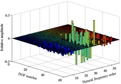
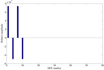
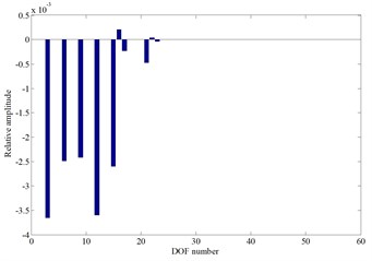
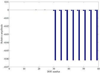
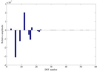
By using regularization method, the system mode shape vector is obtained, as shown in Fig. 3. The DOF number 1-59 in Fig. 3 represents the free degree of system, where 1-18 is the degree of freedom of cutterhead piece and center block, 19-24 is the inner ring gear degree of freedom, 25-27 is the support shield body degree of freedom, and 28-59 is the degree of freedom of pinion and motor. For details, it can be seen the reference [18].
Fig. 3Vibration modes of cutterheader system
4.3. Influence of cutterhead supporting stiffness to natural characteristics and sensitivity
4.3.1. Influence of cutterhead piece supporting stiffness
In the cutterhead system average stiffness matrix , the matrices associated with cutterhead piece tangential supporting stiffness include , , , and (the detailed expressions are shown in Appendix). These matrices are cutterhead piece supporting stiffness matrix and coupled supporting stiffness matrix between each cutterhead piece and center block, and the derivatives of other matrices to the parameter are all equal to 0, so the partial derivative expression of to is presented as follows:
Eqs. (12) is substituted into Eqs. (11), then the sensitivity expression of the th natural frequency to the cutterhead piece tangential supporting stiffness can be obtained:
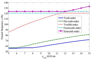
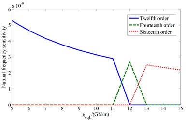
Based on the numerical calculation, the influence of cutterhead piece tangential support stiffness change on the system natural frequency and the sensitivity change law are analyzed. Then the affected cutterhead system natural frequencies and corresponding mode shapes are presented, as shown in Fig. 4.
From the above results, it can be seen that the natural frequencies increase with the value of cutterhead piece tangential support stiffness, and this stiffness mainly affects the system 10-20th order frequencies. Moreover, to illustrate the system vibration characteristics variation law, the A point ( 3.61 GN/m) is taken as an example. When the value of increases, the natural frequency curves of the fifteenth and sixteenth order coincide at point A, and the two order mode shapes are the cutterhead translational vibration mode, as well as the cutterhead and inner ring gear translational overturning coupled vibration mode before point A, respectively (as shown in Fig. 4(c) and Fig. 4(d)). Then the natural frequency sensitivity curves change suddenly after point A, and the mode shapes are synthesized into the cutterhead, inner ring gear translational and motors, pinions torsional coupled vibration mode, which indicates that point A is a sensitive point of the cutterhead piece tangential support stiffness parameter. At this point, with the value change of stiffness, the modal mutation and mode jumping occur. Some other stiffness sensitive points appear in Fig. 4, which include the natural frequency curve crossing points or sensitivity catastrophe points. Near these points, the vibration mode analysis principle is similar, and the mode jumping phenomenon also occurs when the stiffness value is near the sensitive points.
Fig. 4The influence of cutterhead piece tangential support stiffness to natural characteristics
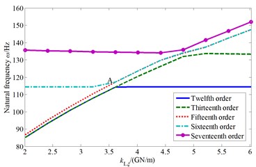
a) Natural frequency change
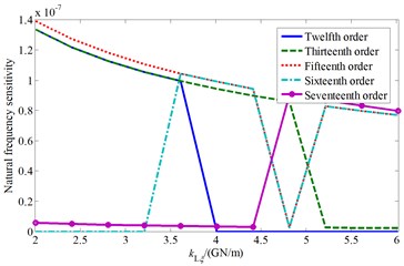
b) Natural frequency sensitivity change
c) The fifteenth mode shape before point A
d) The sixteenth mode shape before point A
4.3.2. Influence of cutterhead center block supporting stiffness
Similarly, the sensitivity expressions of the th natural frequency to the cutterhead center block axial support stiffness and radial support stiffness can be derived as follows:
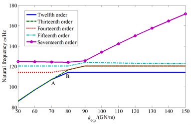
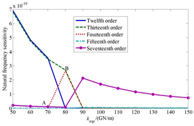
Then the influence curves of the cutterhead center block support stiffness on the natural frequencies and corresponding sensitivity are presented after numerical calculation in Fig. 5.
It can be known from Fig. 5 that the cutterhead center block stiffness also mainly affect the system 10th-20th order frequencies. Similarly, with the value increase of the center block radial support stiffness, it appears bifurcation phenomenon in the natural frequency curves. The twelfth order frequency curve is coincide with the thirteenth order frequency curve before the stiffness value is less than A point value ( 70 GN/m), and the mode shape is the cutterhead, inner ring gear translational and motors, pinions torsional coupled vibration mode. Then the twelfth order mode shape changes into the cutterhead, inner ring gear translational overturning coupled vibration mode after point A. And the thirteenth order mode shape keeps the same at first, and then frequency curve is consistent with the fourteenth order frequency curve at point B ( 80 GN/m) (The corresponding mode shape is the cutterhead translational vibration mode). Near the bifurcation point A and coincidence point B, the cutterhead system mode shapes also change when the parameter values change.
Fig. 5The influence of cutterhead center block support stiffness to natural characteristics
a) Natural frequency change
b) Natural frequency sensitivity change
c) Natural frequency change
d) Natural frequency sensitivity change
4.4. Influence of cutterhead mass parameter to natural characteristics and sensitivity
4.4.1. Influence of cutterhead piece mass
The mass matrix is used to take the partial derivative of cutterhead piece mass , and then substituted into Eqs. (11). So, the sensitivity expression of the th natural frequency to the parameter can be obtained as follows:
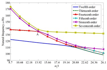
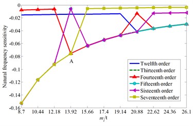
Also, the influence curves of the cutterhead piece mass on the natural frequencies and corresponding mode shapes are drawn, as shown in Fig. 6.
From Fig. 6 it can be showed that the cutterhead piece mass mainly affect the system 10th-20th order frequencies and the natural frequencies decrease with the increase of cutterhead piece mass. The fourteenth and fifteenth order natural frequency curves intersect at point A ( 13.92 t), and the two order mode shapes are the cutterhead and inner ring gear translational vibration mode, as well as the cutterhead translational vibration mode before point A (as shown in Fig. 6(c) and Fig. 6(d)), respectively. Then the two order mode shapes exchange after point A, and the natural frequency sensitivity curves also change suddenly.
4.4.2. Influence of cutterhead rotational inertia
The sensitivity expressions of the th natural frequency to the cutterhead moment of inertia IL can be also derived, as shown in Eq. (17):
And the affected cutterhead system natural frequencies and sensitivity curves are presented in Fig. 7.
As can be seen from Fig. 7, the cutterhead moment of inertia mainly affects the system ninth to eleventh order frequencies.
Fig. 6The influence of cutterhead piece mass to natural characteristics
a) Natural frequency change
b) Natural frequency sensitivity change
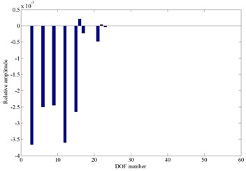
c) The fourteenth mode shape before point A
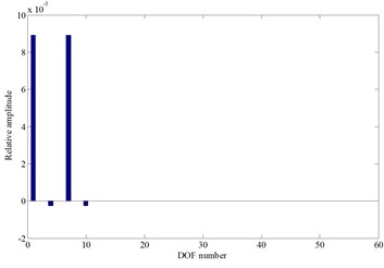
d) The fifteenth mode shape before point A
Fig. 7The influence of cutterhead moment of inertia to natural characteristics
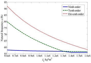
a) Natural frequency change
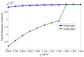
b) Natural frequency sensitivity change
c) The ninth mode shape after cross point
d) The tenth mode shape after cross point
With the increase of this parameter value, the ninth and the tenth order natural frequency curves are interleaved. The ninth order mode shape is the cutterhead, inner ring gear, pinions and motors torsional vibration mode before the cross point, and the tenth order mode shape is the cutterhead and inner ring gear overturning vibration mode. When the cutterhead moment of inertia value is larger than the cross point value, the two order mode shapes change into the pinions and motors torsional vibration mode, as well as the cutterhead, inner ring gear translational overturning coupled vibration mode (as shown in Fig. 7(c) and Fig. 7(d)), respectively. Also, there is an inflection point in the tenth order natural frequency sensitivity curve, and the mode jumping also occurs near the inflection point.
5. Conclusions
1) The cutterhead system natural frequency sensitivity expressions are deduced by the modal method, and the sensitivity expressions of each frequency to the stiffness parameters and mass parameters are obtained, based on the established cutterhead system vibration model.
2) An actual cutterhead system is taken as an example, the influence of the cutterhead support stiffness on each natural frequency and sensitivity is analyzed. The results show that the cutterhead support stiffness mainly affect the 10th-20th order frequencies, and with the stiffness value change, it occurs many crossing points or bifurcation points in the frequency curves. Near these points, the sensitivity curves change suddenly, and the mode shapes also change, to cause the mode jumping phenomenon. It is necessary to keep away from the stiffness sensitive points in actual design, to avoid the system vibration response uncontrollability.
3) In addition, the influence of the cutterhead mass parameter on each natural frequency and sensitivity is also analyzed. It indicated that the cutterhead piece mass also mainly affect the 10th-20th order frequencies, and the cutterhead moment of inertia mainly affect the system ninth to eleventh order frequencies. Similarly, with the cutterhead mass value change, the natural frequency curves are interleaved, and many inflection points also appear in the sensitivity curves. It is also required to avoid the natural frequency parameter sensitive points while matching the cutterhead mass parameters.
References
-
Sun W., Zhu Y., Huo J. Z., et al. Predict and analysis the locations of fatigue crack in TBM cutterhead based on crack failure regions division. Journal of Mechanical Engineering, Vol. 54, Issue 1, 2018, p. 27-35, (in Chinese).
-
Cheng Y. Y. Failure Analysis and service repair technology of open type TBM cutterhead. Welding Technique, Vol. 47, Issue 6, 2018, p. 100-102, (in Chinese).
-
Hopkins M. J., Foden R. L. The in-situ measurement of dynamic cutter forces on raise borer reaming heads. Proc., Conf. on Mining Machinery, Brisbane, Vol. 7, 1979, p. 335-338.
-
Samuel Seow Disc Force measurements on a full-face tunnelling machine. International Journal of Rock Mechanics and Mining Sciences and Geomechanics Abstracts, Vol. 21, Issue 2, 1984, p. 83-96.
-
Maleki R., Mahdi Rock Joint Rate (RJR); a new method for performance prediction of tunnel boring machines (TBMs) in hard rocks. Tunnelling and Underground Space Technology, Vol. 73, 2018, p. 261-286.
-
Rostami J. Performance prediction of hard rock tunnel boring machines (TBMs) in difficult ground. Tunnelling and Underground Space Technology Incorporating Trenchless Technology Research, Vol. 57, 2016, p. 173-182.
-
Rostami J., Chang S. A closer look at the design of cutterheads for hard rock tunnel-boring machines. Engineering, Vol. 3, Issue 6, 2017, p. 892-904.
-
Liu Z. J., Teng H. F., Shi Y. J., et al. Cutterhead design key issues of a full face rock Tunnel Boring Machine (TBM). Chinese Journal of Mechanical Engineering, Vol. 19, Issue 16, 2008, p. 1980-1985, (in Chinese).
-
Geng Q., Wei Z. Y., Meng H., et al. Free-face-assisted rock breaking method based on the multi-stage tunnel boring machine (TBM) cutterhead. Rock Mechanics and Rock Engineering, Vol. 49, Issue 11, 2016, p. 4459-4472.
-
Zhang X. H., Xia Y. M., Liu J., et al. Study on characteristics of breaking rock by double edge central disc cutter under confining pressure. Journal of Northeastern University (Natural Science), Vol. 38, Issue 6, 2017, p. 839-844, (in Chinese).
-
Lin L. K., Xia Y. M., Jia L. H., et al. Influence of installation and tunneling parameters on rock-breaking resistance of disc cutter. Journal of Zhejiang University (Engineering Science), Vol. 52, Issue 6, 2018, p. 1209-1215, (in Chinese).
-
Tang Q., Yang Y., Xia Y. M., et al. Numerical and experimental study on rock breaking by cutter in rolling model. Journal of Hunan University (Natural Science), Vol. 45, Issue 8, 2018, p. 69-78, (in Chinese).
-
Li J., Nie Y. F., Fu K., et al. Experiment and analysis of the rock breaking characteristics of disc cutter ring with small edge angle in high abrasive grounds. Journal of the Brazilian Society of Mechanical Sciences and Engineering, Vol. 40, 2018, p. 505, https://doi.org/10.1007/s40430-018-1422-z.
-
Pan Y. C., Liu Q. S., Peng X. X., et al. Full-scale rotary cutting test to study the influence of disc cutter installment radius on rock cutting forces. Rock Mechanics and Rock Engineering, Vol. 51, 2018, p. 2223-2236.
-
Han M. D., Cai Z. X., Qu C. Y., et al. Dynamic numerical simulation of cutterhead loads in TBM tunnelling. Tunnelling and Underground Space Technology, Vol. 70, 2017, p. 286-298.
-
Liu J. Q., Bin H. C., Guo W. Load characteristics of the TBM cutterhead under mixed-face rock ground condition. Journal of Harbin Engineering University, Vol. 39, Issue 3, 2018, p. 575-583, (in Chinese).
-
Guo W., Song L. W., Zhu D. H., et al. Matching characteristics analysis of TBM cutterhead boring parameters and disc cutter spacing based on energy principle. Journal of Tianjin University (Science and Technology), Vol. 50, Issue 2, 2017, p. 128-134, (in Chinese).
-
Sun W., Ling J. X., Huo J. Z., et al. Dynamic characteristics study with multidegree-of-freedom coupling in TBM cutterhead system based on complex factors. Mathematical Problems in Engineering, Vol. 3, Issue 2013, 2013, p. 657-675.
-
Huo J. Z., Wu H. Y., Yang J., et al. Multi-directional coupling dynamic characteristics analysis of TBM cutterhead system based on tunnelling field test. Journal of Mechanical Science and Technology, Vol. 29, Issue 8, 2015, p. 3043-3058.
-
Huo J. Z., Hou N., Sun W., et al. Analyses of dynamic characteristics and structure optimization of tunnel boring machine cutter system with multi-joint surface. Nonlinear Dynamics, Vol. 87, Issue 1, 2017, p. 237-254.
-
Huo J. Z., Wu H. Y., Sun W., et al. Electromechanical coupling dynamics of TBM main drive system. Nonlinear Dynamics, Vol. 90, Issue 4, 2017, p. 2687-2710.
-
Lin J., Parker R. G. Sensitivity of planetary gear natural frequencies and vibration modes to model parameters. Journal of Sound and Vibration, Vol. 228, Issue 1, 1999, p. 109-128.
About this article

This work is financially supported by the National Natural Science Foundation of China (51775113), the Natural Science Foundation of Fujian Province, China (2017J01675), Science and Technology Plan (Guidance) of Fujian Province, China (2017H0002), and Scientific Research Foundation of Fujian University of Technology (GY-Z160048).
