Abstract
With extreme complexity, the drilling process is a dynamic process which is severely influenced by longitudinal vibration. Longitudinal vibration, as one of the most important reason, is directly generated by the fatigue failure of the bottom hole assembly. In this paper, the natural frequencies of longitudinal vibration along the drillstring are analyzed by the finite element method. The deformed plot, stress nephogram, and displacement contour map under 1 to 4 ordered the natural frequency of the longitudinal vibration are obtained. The analysis results show that the maximum deformation always appears in the central part of the string so that some technological process on these positions is required to reduce the collision between the string and wellbore wall. Additionally, a time series of longitudinal vibration of a bottom rotating drillstring is extracted from real-time field data, which is measured while drilling near the drill bit. Then the time-frequency and energy spectrum analysis of the longitudinal vibration is carried out. The results of the statistical analysis show that, when the drillstring uniformly rotates, the longitudinal vibration can be considered as a kind of random vibration. However, if the stick-slip phenomenon occurs during the drilling process, the energy concentration will appear in the time series spectrum of the longitudinal vibration, by which means the vibration could be regarded as random no longer.
Highlights
- The natural frequencies of longitudinal vibration along the drillstring is analyzed by finite element method
- The time series of longitudinal vibration of a bottom rotating drillstring is extracted from real-time field data
- The results of statistical analysis show that, when the drillstring uniform rotates, the longitudinal vibration can be considered as a kind of random vibration
1. Introduction
In the field of oil and gas drilling engineering, drilling dynamics is one of the most important problems which is attracted the attention of engineers for more than half a century. It has been proved that drilling dynamics and its interactions with the surroundings is the essential reason of a lot of dangerous drilling accidents, such as the poor cementing quality induced by the deterioration of borehole quality and the failure of drilling tools caused by strong vibration [1]. As the most common dynamics phenomenon, severe vibrations of drillstring must be attached with great importance to. The drillstring is consists of several drill pipes, drill collars, stabilizers and connections, both of them are under heavy dynamic loads with extreme complexity [2]. If the excited frequency of drillstring closes to the natural frequencies of its components, the energy will be absorbed. Once the resonance appears and the energy boosts, the amplitude of string vibration will be increased and the bending of the string will be intensified, by which the early fatigue of tools may occur and the tools life will be reduced significantly. There are three typical modes of drillstring vibration, namely are the longitudinal vibration (also called axial vibration) mode, the transverse (also referred to lateral or bending) mode and the torsional (also known as stick-slip) mode [3]. The destructive nature of each type of vibration is different, among them, the longitudinal vibration owns the most intuitionistic destructive behavior and action. The axial vibration of the drillstring can be defined using discrete mass segments and springs [4] and the frequency response function can be used to demonstrate the similarity of the model to the real drillstring response. The axial vibration problem would more obvious during the extreme-depth wells, velocity changes at the top of the drillstring can produce transient axial pulse excitation. Lubinski [5] investigates the dynamics of the drillstring during tripping movement. Aadnoy et al. [6] studies using the static model of the drillstring and the rotation of the drillstring to reduce the drillstring borehole friction during torsional vibration.
In order to research the longitudinal vibration of drillstring, lots of models have been developed. An early study was conducted by Bailey J. J. [7], in which the axial natural frequencies of drillstring was derived by a partial differential equation with an undamped model of longitudinal bar vibration. Since then, using the linear partial differential equation became the analysis method of most uncoupled axial vibration. After that, a classical linear-damped axial wave equation was proposed by Kreisle and Vance [8] as the governing equation, which can be solved by using the Laplace transformation. Then, the effect of the length of the bottom-hole assembly (BHA) on the axial resonance of the drillstring is studied by Dareing [9, 10] with a developed damped axial wave equation. The axial vibrations of the drillstring using discrete mass segments and springs was modeled by Elsayed and Phung [4], the comparative analysis of the response of real drillstring and the model was carried out by frequency response function (FRF), and the similarity is proven. The axial vibration problem would more obvious during the extreme-depth wells, during which a transient axial impulse excitation could be created by the velocity change of the top of drillstring. Lubinski [5] was one of the earliest researchers who studied the dynamic of this phenomenon. Furthermore, the friction between the drillstring and the wellbore during tripping motion was investigated by Aadnoy et al. [6], and the fiction reduction method using the rotation of the drillstring was proposed. Some studies are dedicated to better understanding the full dynamics of rotary drilling systems [11-13]. Sunit [14] develops the global dynamics of coupled axial torsional vibration and the possibility of bit bounce.
Additionally, depth research of the dynamical motion state of the BHA is very necessary and urgent, for directional drilling tools like rotary steerable system (RSS) [15]. The RSS exerts steer force while the drillstring is rotating during the directional drilling process, though the torque and drag are partially reduced, as a new problem, the weight on bit (WOB) and the torque transferred to the bit is reduced simultaneously. With more advanced measurement while drilling (MWD) technology appear successively, it has become the trend in recent years that the use of downhole measurement data to analyze the mechanical properties and vibration characteristics of the BHA [16]. Especially, we could obtain the data form the near-bit measurement [17], which is a technology that installs the measurement system near the drilling bit. Thus, we can analyze the drilling bit vibration that could be supported by field data. However, there is no report describing the vibration characteristics of the drillstring with the measurement time series. This paper based on the simulation study of frequency-division multiplexing (FDM), measured the drill bit vibration real-time and the frequency is up to 100 Hz. The system stored sampling data real-time in the real drilling process, which could be play backed after drilling. Thus, we can obtain the massive time series data of the drillstring vibration. Then we use time series analysis method to further study the dynamics of longitudinal vibration on bottom drilling tools (BDT) with measurement data, by which new challenges appeared in the vibration modeling, like new drilling techniques such as directional and vibration-assisted rotary drilling, could be further explained comprehensively.
This paper obtain the natural frequencies along the drillstring of BDT using the finite element model, get the deformed plot and displacement cloud map of longitudinal vibration as well. Additionally, develop a real-time measurement while drilling system near the drilling bit, and extract the longitudinal vibration time series of bottom rotating drillstring. The results of statistical analysis show that the longitudinal vibration can be regards as random vibration when the drillstring uniform rotating. However, when the drillstring appear stick-slip phenomenon, the energy concentration appeared in the spectrum of the longitudinal vibration time series, which should not be considered as random vibration any more. This is the mainly novelty and achievements of the work in this paper.
2. Mechanical model of longitudinal vibration for BDTs
2.1. Selection and assumptions of the mechanical model
There are more than 5 types of longitudinal free vibration of drillstring model have been developed, in them, three types of most widely used mechanical models are shown in Fig. 1 [18]. Compared with Model 1, Model 2 has omitted the quality of the damper and driving system, which includes the quality of the traveling system, kelly and steel wire rope. In the meantime, Model 3 has ignored the quality of the damper and simplified the quality of drill collar as a focus quality. Due to the best versatility in these mathematical and mechanical models, a lot of special longitudinal vibration can be analyzed by using Model 1, which is currently selected as the longitudinal vibration model of drillstring in this paper. In Fig. 1, and represents the equivalent stiffness coefficient and the equivalent mass of the driving system respectively; and respectively express the stiffness coefficient and the mass of damper, which could be approximately considered as the equivalent integrated structure of BHA; and denotes the length of drill pipe and drilling collar, both of them are considered as two elastic links; and means the length from the sampled differential element to the top of drill pipe and the top of drilling collar respectively.
Fig. 1The longitudinal vibration models of the drillstring
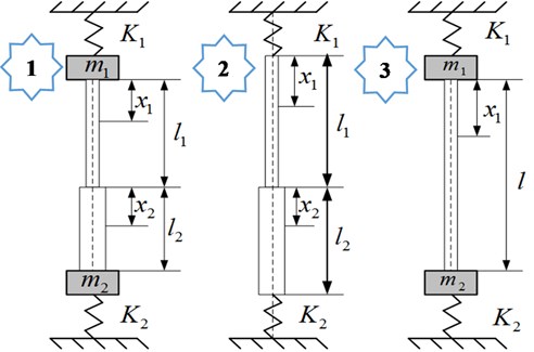
Model 1 consists of drill collar, drill stem, joint, stabilizer, damper, and other downhole tools, which could be assembled by any arbitrary combinations and applied for any arbitrary RPM and WOB. During drilling process, the BDTs are inevitably influenced by disturbing factors, such as WOB induced by disturbing forces, the disturbing torsion on stabilizers, the inertial force induced by rotating of drillstring, the damping and viscosity resistance of drilling fluid, et al. Thus, in order to facilitate an efficient analysis, some assumptions must be proposed as follow: (a) With homogeneous density, the drillstring is an elastic straight bar owning a circular cross section, the inner and outer peripheries of which is rigid; (b) The inner wall of borehole is rigid, the annular between borehole and drillstring is a circular ring, the friction between them is neglected; (c) The top driving system is simplified as a spring, the quality and stiffness coefficient of which is and respectively; (d) The vibration is derived from the interaction between drill bit and rock, by which the motion of bit can be regarded as a kind of resonance vibration observing sine or cosine changing alone with time.
2.2. Mathematic model of drillstring
Based on the assumptions above, the longitudinal vibration equation of drillstring can be deduced by elastic rod theory, the partial differential equation of drillstring longitudinal vibration can be given as follow:
wherein, is the length from the sampled differential element to the top end of drillstring, is the displacement of sampled differential element along the borehole axis direction, and respectively refer to time and wave velocity of longitudinal vibration, here , in which and respectively refers to the elastic modulus and the density of steel. Eq. (1) can be solved by the method of separation of variables, here we set:
wherein refers to the variable function of phase position, which is related to the variable of time and location-independent; refers to the variable function of vibration amplitude, which is related to the variable of location and location-independent. With Eq. (2), Eq. (1) can be rewritten as:
Here we introduce as the natural frequency of the drilling system and set:
Then the solution of the partial differential equation Eq. (1) can be transformed to the solution of the ordinary differential equation as follow:
The general solution of Eq. (5) is:
wherein , , , and are integration constant. Here we bring the lower corner mark 1 and 2 referring to the drillstring and the drill collar respectively, the displacement of longitudinal vibration of drillstring and drill collar can be given as:
wherein, and respectively represents the displacement of longitudinal vibration of drillstring and drill collar; , , and , , are different undetermined integration constant for drillstring and drill collar. Taking the partial derivation of Eq. (6) with and , the equation group can be obtained as follow:
To solve the equations, some boundary equations must be given according to boundary conditions. On the top end of drillstring, when 0, on the basis of mechanical equilibrium theory:
wherein is the area of the cross-section of drillstring. On the interface between drillstring and drill collar, when , 0, according to the conditions of equal tension and equal velocity:
wherein is the area of the cross section of the drill collar. On the bottom of drill collar, when , the mechanical equilibrium equation can be given as:
By using Eq. (8) plug into the boundary condition equations from Eq. (9) to Eq. (12), the frequency equation of Model 1 can be deduced as:
Then the natural frequency of the longitudinal vibration of drillstring system can be solved, which is directly influenced by the stiffness coefficient of the damper. Because Eq. (13) is a nonlinear equation, in order to acquire an effective solution, the finite element method is selected.
2.3. Influence of interior drilling fluid
The influence of drilling fluid to the drillstring inherent frequency is mainly on mass effect, the drilling fluid influence reflects to be the equivalent mass change of the drillstring participated the drill fluid inside vibration with the drillstring, the mass of which is called interior drill fluid additional mass.
Assuming that the length of drillstring is , and its mass is:
The drill fluid inside drillstring is:
Then the mass of drill sting with inside fluid:
Interior additional mass is:
Take Eq. (16) into Eq. (15):
Then the interior drill fluid additional mass will be obtained:
In Eq. (14-19), is interior drill fluid additional mass coefficient, is the inside diameter of drillstring, is outer diameter of drillstring, is drillstring mass, is interior drill fluid mass, is drillstring material density, is drill fluid density.
3. Analysis method of longitudinal vibration
3.1. Finite element analysis method
The drillstring can be abstracted as a composite structure which is consisted of finite elements [19]. In this structure, every element is an elastic body and the displacement of its node can be expressed by interpolation function. Here we set represents an array vector of the node in element , which is a function changing with time. According to a given displacement interpolation method, the displacement of an arbitrary point in element , here denoted by , can be expressed by matrix equation as:
wherein is the functional matrix. Then the strain vector and the stress can be given as:
wherein is the geometric matrix, which is a matrix connected with the strain and the displacement of the node; is the elastic matrix, which can be also called the material matrix. Then the stiffness matrix of the element is obtained:
3.2. Frequency analysis methods
In order to completely analyze the changing of the signal spectrum with time, as one of the most advanced methods, Gabor transforms is selected to make the analysis of dynamic spectral [20]. Due to the close relationship with wavelet transforms, the analysis of vibration signal of drillstring can always be effectively carried out by Gabor transforms, by which the sinusoidal frequency and phase content of local sections of a signal can be determined as it changes with time. During this process, the function is needed to be transformed firstly by multiplying a Gaussian function, which is considered as a window function, then a Fourier transform is used to transform the resulting function above secondly to derive the time-frequency analysis. By using the fast Fourier transforms (FFT) algorithm, Fourier transforms for this time series of the accelerated speed of the vibration signal can be obtained as:
wherein is the sample interval, is the accelerated speed of vibration, is the total sampling amount of the time series, and is the normalized frequency. Then its power spectral density (PSD) can be approached by using Welch’s method [21]. This method is based on the concept of using periodogram spectrum estimates, which are the result of converting a signal from the type of time domain to another type of frequency domain. During this analysis, the noise reduction is always desired to avoid the negative influence of noise caused by imperfect and finite data. As an exchange, the noise in an estimated power spectrum is reduced by Welch’s method while the frequency resolution is being sacrificed. Then the PSD of the vibration signals can be gained by:
The energy distribution of Gabor Function is expressed by using a time-frequency box. By using the method of Gabor transform, the differences of longitudinal vibration pattern can be discriminated. Then the Fourier transform of the window function can be obtained:
wherein and respectively refer to the width of the time interval and the center point.
4. Analysis of the natural frequency of the longitudinal vibration
The ANSYS software is chosen in this paper to do the analysis of the natural frequency of the longitudinal vibration of BDTs by model 1 mentioned above, the upper-end face of the drill collar is fixed with the upper drill pipes. The lateral displacement of both drill pipes and drill collar are constrained by the rigid peripheries according to assumption (a), thus the nodes of which can only vibrate along the axial direction. Mixed meshing method is used during the finite element analysis, in order to reduce the appearance of hourglass modes, hexahedron meshes are used as much as possible to avoid using tetrahedral meshes. The elasticity modulus and the density of drillstring are respectively set as 2.1×10¹¹ Pa and 7.8×10³ kg/m3. Then the results are obtained for drill collars with a different length under 10 modes, which can be sufficiently expressed the motion state on basis of lots of engineering studies. The influence of static force, such as the weight of drill collar, buoyancy of drilling fluid and WOB, is ignored.
The nature frequency of the longitudinal vibration of different drill collars under 1st to 10th order is shown in Table 1. The results show that with the length of the drill collar increases, the nature frequency of longitudinal vibration of drill collar decreases slightly. Meanwhile, with the order of mode increases, the nature frequency increases and the increasing range grows largely. This regular changing phenomenon is very meaningful for adjusting the nature frequency of drillstring by optimizing the design of BDTs, especially in lower natural frequencies district, the resonance induced by longitudinal vibration can be avoided effectively.
Table 1The nature frequency of longitudinal vibration of drill collar
Length of drill collar (m) | Nature frequency (Hz) | ||||
1st order | 2nd order | 3th order | 4th order | 5th order | |
7 | 169.96 | 225.73 | 225.77 | 310.89 | 311.20 |
14 | 168.82 | 224.65 | 225.30 | 310.03 | 310.80 |
28 | 165.49 | 220.40 | 222.87 | 302.23 | 302.98 |
6 order | 7 order | 8 order | 9 order | 10 order | |
7 | 353.69 | 353.99 | 530.75 | 679.24 | 679.66 |
14 | 350.16 | 350.96 | 522.67 | 660.38 | 660.83 |
28 | 345.27 | 345.80 | 514.19 | 638.12 | 639.34 |
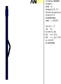
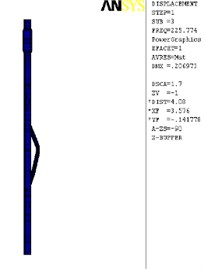
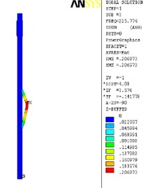
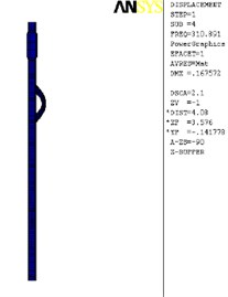
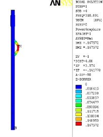
The finite element analysis of the longitudinal vibration of the drill collar is carried out under the natural frequency with the order from 1st to 4th. Due to the extensive applicability, a drill collar with the length of 7 m (the outer and inner diameter is 121 mm and 51 mm) is selected as the research object sample in this paper, and the deformed plot, the stress nephogram, and the displacement contour map under 1st to 4th ordered the natural frequency of the longitudinal vibration is respectively shown as Fig. 2, Fig. 3 and Fig. 4, these three different kinds of nephogram is one-to-one correspondence. The results show that the maximum displacement under 1st to 4th order of the natural frequency is 0.030244 m, 0.20697 m, 0.206973 m and 0.167572 m, the position in coordinate system is (7.3883, 0, 0.121), (3.1198, –0.055, 0.3702), (3.1197, 0.3518, 0.0587) and (4.8032, 0.3518, 0.062) in sequence. All the maximum displacement occurs in the string internal, and once the order is larger than 1, the lateral deformation appears as shown in figures. These results mean that, for the sake of reducing the longitudinal vibration, some countermeasures like mounting on dampers should be taken to constrain the deformation within the internal of drill collar, then the collision between the BDT and the borehole wall would be reduced effectively.
The simulation of the natural vibration frequency of the drillstring under free state is compared with the experimental value [28], It can be seen that experimental values of natural frequencies under the free state of the experimental column correspond well with the calculated values and the relative errors are small (< 2 %), indicating that the simulation is reliable.
Fig. 2The deformation plot, stress nephogram, and displacement contour map of the longitudinal vibration
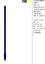
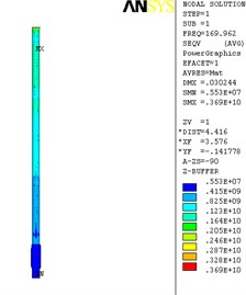
a) 1st order
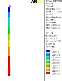
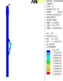
b) 2nd order
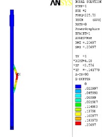
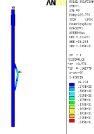
c) 3th order
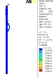
d) 4th order
5. Vibration analysis of BDT based on measurement data
Besides the theoretical research, the measurements of drillstring vibration in field were carried out by drilling engineer. To understand the intensity of drilling string vibration, S. D. Alley used Measurement While Drilling (MWD) to measure vibration parameters, the results show that the drillstring vibrates violently while drilling [22, 23]. The latest measurements were measured by the micro-vibration logging tool, which was directly mounted on the drill bit to avoid interference of other downhole tools, so the vibration characteristics of the drillingstring and the fluctuation of WOB will be truly reflected by the measurements. The measurements indicate that the fluctuation of WOB is 1-2 times of nominal WOB. And when the drilling string violently vibrates, there is no pressure on the bit, which means the bit has vibrated from away the bottom in the well.
Based on the analysis mentioned above, the optimized BDT with high reliability is used in field applications safely, the measured signals while drilling is collected. As an advanced BDT component widely used in oil and gas industry, a rotary steerable system (RSS) with the push-the-bit mode is installed near the bit for directional drilling, the whole drillstring of the drilling system is rotated from the surface by a top drive, which is typically a hydraulically driven mechanism. During directional drilling using RSS, specialized downhole equipment is employed to replace conventional directional tools such as mud motors. For RSS using push-the-bit mode, its push pads in implementing agency alternately in turn pushed against the borehole wall, making the bottom hole constantly under a cycle of nonlinear damping force, by which the movement of the BDT would be transformed to chaos and disorder. Thus, it is necessary and urgent for us to do some thorough research about the dynamic state of BDT, especially for RSS. High-sample-rate downhole dynamics sensors were placed at 1.5 ft above the bit in the BHA. These dynamics sensors (shown in the Fig. 3(b)) had a sample rate of 100 Hz and consisted of a package measurable functions for lateral, torsional, and axial vibration. This measurement system also included a magnetometer, which was used to calculate downhole drillstring rotating speed. Additionally, redundancy design is adopted during measure process, some extra sensors are mounted on to avoid the failure of few of them, and the data of both dynamics sensors and magnetometer can be checked by each other by using calculated methods [24].
Fig. 3Measurement system: a) the simplified diagram of bottom-hole assembly [14]; b) the configuration of measurement system
![Measurement system: a) the simplified diagram of bottom-hole assembly [14]; b) the configuration of measurement system](https://static-01.extrica.com/articles/20395/20395-img14.jpg)
In Fig. 3, , , are defined as measured signals of triaxial accelerometers along the -, -, - axis respectively. Under certain sample frequency, the measured signal is a time series which can be represented by a function changing with time. We can use define the lateral vibration of the BHA and use express the longitudinal vibration.
The spectrum of time-frequency of the longitudinal vibration signals is shown in Fig. 4. Fig. 4(a) is sequence diagram of longitudinal vibration, getting from charts, longitudinal vibration has a smaller amplitude than horizontal vibration. Fig. 4(b) is a frequency range chart as correspondingly, signals also have no obvious characteristic frequency, can be disposed of random signals. From distribution density of vibration ranges, as shown in Fig. 4(c), the range of longitudinal vibration mostly occurred between 0-2G, smaller than horizontal vibration. As shown in Fig. 4(d), the power spectrum density worked by period plan estimation, extreme values occurred on three frequencies, proving time sequence of longitudinal vibration intensified at some frequencies, it may be related to formation lithology. The acceleration signals at -axis have apparent noise spectrum characters, proving under the rotation state, vibration of drilling tools have more regularly influence to the signals of accelerated signals at axial direction.
Fig. 4Time-frequency analysis of the longitudinal vibration
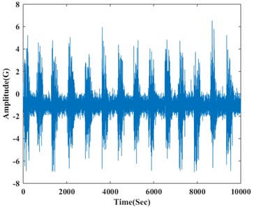
a) Time-domain plot
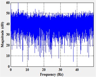
b) Frequency range chart
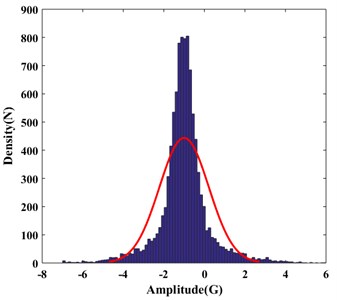
c) Distribution density
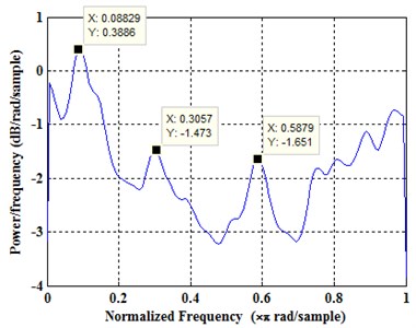
d) PSD
Comparing with horizontal vibrations, longitudinal vibrations are bare, the acceleration sensors at -axis are influenced by vibration of drill columns hardly, under the condition of the rotation. Acceleration sensors are put on the center axis of drilling supporter, not influenced by rotation speed of drilling tools theoretically, so under a short time period, the time sequence of accelerated speed measurement signals at -axis should be a line paralleled to the -axis. Based on the analysis above, the filtering of signals on the accelerate sensor at -axis is much easier to realize than -axis and -axis’s. As the analysis of horizontal vibration, use instant Fourier transform to make vibration time-frequency energy contour under two conditions of stick-slip or not.
Using the FFT algorithm for the time series of vibration is:
Then its power spectral density will be obtained:
We using time-frequency box to express the energy distribution of Gabor function. the method of Gabor transform can help us discriminate the rotational movement pattern. Then Fourier transform of the will be obtained:
As shown in Fig. 5, when there is no stick-slip vibration of drillstring, the time-frequency has no point of concentration, disposing of the random signals like the same before. But when it does exist stick-slip phenomenon, there are stripes occurred on time-frequency contour, illustrating stick-slip vibration not only reflects the change of rotation speed, but also influences the longitudinal vibration of drillstring, making the signals of longitudinal vibration lose the random characters. Because the signals of longitudinal vibration are barely influenced by noise interference, and the longitudinal component of acceleration of gravity is constant whether drillstring rotating or not, so in the disposing of signals, to decrease the calculated amount, the reverse and rotating vibration can be ignored during the disposing of signals of longitudinal vibration, treating noise signals as random.
The results show that, during the whole drilling process, the chaotic phenomenon of the vibration of the drilling bit is existence all the time. In order to rediscover the phenomenon of drillstring vibration and improve the control algorithm used in drillstring vibration, finding the chaotic characteristics of longitudinal vibration in field measurement data of drillstring vibration [25-27] is extremely helpful for engineering application.
Fig. 5The energy spectrum of the longitudinal vibration signal: a) non-stick-slip, b) stick-slip
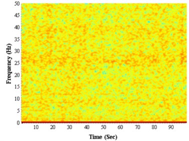
a)
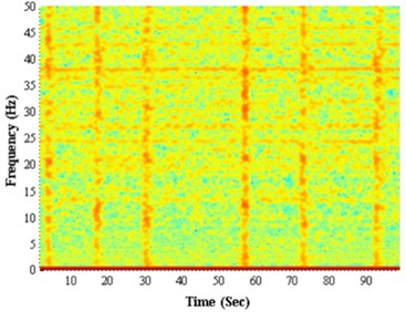
b)
6. Conclusions
During the process of drilling, the vibration of BDT is a widespread phenomenon that has focused the attention of so many scholars. Create a more accurate theoretical model of the drillstring vibration is difficult due to the impact of complex downhole conditions, but with the development of downhole measurement technology, it becomes possible to study the dynamic characteristics of drillstring by measuring the vibration signal while drilling. Nowadays, the downhole measurement tool can achieve and storage three-dimensional vibration signals in real-time, by which convincing data can be provided to support the dynamic studies of BDTs. Nowadays, the downhole-drilling tool can achieve three-dimensional vibration measurements with the development of downhole measurement technology, thus provided convincing data support for the studies of bottom drilling tool dynamics. Some even suggested that the use of the downhole vibration signals in real-time to determine formation lithology, however, these data are generally coming from some commercial companies, because the relationship of the commercial competition, many researchers cannot get the real measurement data from the field test, many studies have also only limited to the laboratory.
In this paper, according to the model of the drilling system, the natural frequencies are analyzed along the drillstring mounted on BDTs by using the finite element model, the deformed plot, stress nephogram and displacement contour map of longitudinal vibration are obtained as well. According to the natural frequencies, the appearance of the resonance can be avoided by optimizing the design of BDTs, then the reliability can be enhanced. Under the guaranty of the reliability, the longitudinal vibration signal of BDT, including drill collars together with the BDT, is analyzed by field data extracted from measured signals while drilling. The statistical analysis results show that the longitudinal vibration of the BDT is a kind of broadband vibration, which is consisted of several kinds of vibrations induced by comprehensive factors. There are frequency peaks existed in the PSD figure, but the position of the peaks cannot be predicted. The longitudinal vibration of the BDT can be considered as random vibration when the drillstring rotates uniformly. However, if the stick-slip of the drillstring appears, the phenomenon of energy concentration will appear in the spectrum of the time series of longitudinal vibration, therefore the vibration should not be regarded as random anymore. This paper obtains the natural frequencies along the drillstring of BDT system using the finite element model, get the deformed plot and displacement cloud map of longitudinal vibration as well. Additionally, develop a real-time measurement while drilling system near the drill bit, and extract the longitudinal vibration time series of bottom rotating drillstring. The results of statistical analysis show that the longitudinal vibration can be regards as random vibration when the drillstring uniform rotating.
The analysis of the influence of longitudinal vibration reveals some characteristics of BDT during the drilling process, and lays a foundation of the research of coupling the stick-slip vibration and transverse vibration. The complex dynamics of BDTs will be comprehensively explained, some instructions will be proposed for drilling technology.
References
-
Ritto T. G., Escalante M. R., Rubens Sampaio, Rosales M. B. Drillstring horizontal dynamics with uncertainty on the frictional force. Journal of Sound and Vibration, Vol. 332, 2013, p. 145-153.
-
Liu X., Vlajic N., Long X., et al. Coupled axial-torsional dynamics in rotary drilling with state-dependent delay: stability and control. Nonlinear Dynamics, Vol. 78, Issue 3, 2014, p. 1891-1906.
-
Liu X., Vlajic N., Long X., et al. Nonlinear motions of a flexible rotor with a drill bit: stick-slip and delay effects. Nonlinear Dynamics, Vol. 72, Issue 1, 2013, p. 61-77.
-
Elsayed M. A., Phung C. C. Modeling of drillstrings. Proceedings of the 24th ASME International Conference on Offshore Mechanics and Arctic Engineering, Halkidiki, Greece, 2005.
-
Lubinski A. Dynamic loading of drillpipe during tripping. Journal of Petroleum Technology, Vol. 40, Issue 8, 1988, p. 975-983.
-
Aadnoy B. S., Fazaelizadeh M., Hareland G. A 3D analytical model for wellbore friction. Journal of Canadian Petroleum Technology, Vol. 49, Issue 10, 2010, p. 25-36.
-
Bailey J. J., Finnie I. An analytical study of drillstring vibration. Journal of Engineering for Industry, Vol. 2, Issue 82, 1960, p. 122-128.
-
Kreisle L. F., Vance J. M. Mathematical analysis of the effect of shock sub on the longitudinal vibrations of an oil well drillstring. SPE Journal, Vol. 4, Issue 10, 1970, p. 349-356.
-
Dareing D. W. Guidelines for controlling drillstring vibrations. Journal of Energy Resources Technology, Vol. 2, Issue 106, 1984, p. 272-277.
-
Dareing D. W. Drill collar length is a major factor in vibration control. Journal of Petroleum Technology, Vol. 4, Issue 36, 1984, p. 637-644.
-
Khulief Y. A., Al-Naser H. Finite element dynamic analysis of drillstrings. Finite Elements in Analysis and Design, Vol. 41, Issue 13, 2005, p. 1270-1288.
-
Sampaio R., Piovan M. T., Venero Lozano G. Coupled axial/torsional vibrations of drill-strings by means of non-linear model. Mechanics Research Communications, Vol. 34, Issue 5, 2007, p. 497-502.
-
Kapitaniak M., Hamaneh V. V., Chávez J. P., et al. Unveiling complexity of drill-string vibrations: Experiments and modelling. International Journal of Mechanical Sciences, Vols. 101-102, 2015, p. 324-337.
-
Sunit K., Gupta N., Pankaj Wahi Global axial-torsional dynamics during rotary drilling. Journal of Sound and Vibration, Vol. 375, Issue 4, 2016, p. 332-352.
-
Warren Tommy Rotary steerable technology conclusion: implementation issues concern operators. Oil and Gas Journal, Vol. 96, Issue 12, 1998, p. 23-24.
-
Andrew Craig, Goodship Rachel, Shearer David High frequency downhole dynamic measurements provide greater understanding of drilling vibration in performance motor assemblies. Drilling Conference and Exhibition, New Orleans, Louisiana, USA, 2010.
-
Ledgerwood III L. W., et al. Downhole vibration measurement, monitoring and modeling reveal stick-slip as a primary cause of PDC bit damage in today’s applications. SPE Annual Technical Conference and Exhibition, Florence, Italy, 2010.
-
Zhao Guozhen, Gong Weian Fundamentals of Drilling Mechanics. Petroleum Industry Press, China, 1988.
-
Lee H. H. Finite Element Simulations with ANSYS Workbench 17. SDC Publications, 2017.
-
Ding Jianjiun Time Frequency Analysis and Wavelet Transform Class Note. Department of Electrical Engineering, National Taiwan University (NTU), Taipei, Taiwan, 2007.
-
Welch P. D. The use of fast Fourier transform for the estimation of power spectra: a method based on time averaging over short, modified periodograms. IEEE Transactions on Audio Electroacoustics, Vol. 15, Issue 62, 1967, p. 70-73.
-
Alley S. D., Sutherland G. B. The use of real-time downhole shock measurements to improve BHA component reliability. SPE Annual Technical Conference and Exhibition, Dallas, Texas, 1991.
-
Tian Jialin, Wu Chunming, Yang Lin, Yang Zhi, Liu Gang, Yuan Changfu Mathematical modeling and analysis of drill string longitudinal vibration with lateral inertia effect. Shock and Vibration, Vol. 2016, 2016, p. 6281264.
-
Xue Qilong, Wang Ruihe, Sun Feng, Huang Zhiyuan Chaotic vibration analysis of the bottom rotating drill string. Shock and Vibration, Vol. 2014, 2014, p. 429164.
-
Fushen Ren, Baojin Wang, Suli Chen, Zhigang Yao, Baojun Bai Nonlinear model and qualitative analysis for coupled axial/torsional vibrations of drill string. Shock and Vibration, Vol. 2016, 2016, p. 1646814.
-
Xue Qilong, Leung Henry, Wang Ruihe, et al. The chaotic dynamics of drilling. Nonlinear Dynamics, Vol. 3, Issue 83, 2016, p. 2003-2018.
-
Xue Qilong, Leung Henry, Huang Leilei, et al. Modeling of torsional oscillation of drillstring dynamics. Nonlinear Dynamics, Vol. 96, Issues 1, 2019, p. 267-283.
-
Yang C., Wang R., Han L., Xue Q. Analysis on the lateral vibration of drill string by mass effect of drilling fluid. Journal Mechanical Sciences, Vol. 10, 2019, p. 363-371.
About this article

The author(s) disclosed receipt of the following financial support for the research, authorship, and/or publication of this article: This work was supported by Natural Science Foundation of China (51704264), National Project “R&D of Key Tools and Equipment for Accelerating Drilling Speed and Efficiency in Complex Formations” (No. 2016ZX05021-003), National Key R&D Program of China (2016YFE0202200).
