Abstract
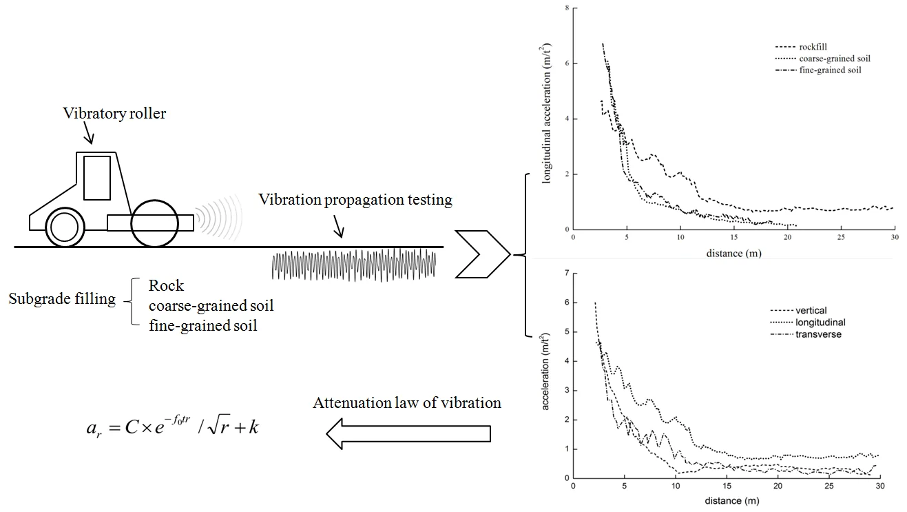
When a high-power vibrating roller compact the subgrade, the vibration wave will quickly propagate along the surface of the subgrade and generate hazards to surrounding environment and structure. To study the vibration propagation rules of the roller, the vibration acceleration of the high-power vibrating roller was measured on the surface of the rock subgrade, coarse-grained soil subgrade and fine-grained soil subgrade. The respective relations between vibration acceleration and the distance from a vibration source in the vertical, horizontal radial and horizontal circumferential direction have been discovered. The research results show that the vibration peak frequency generated by the vibrating roller on the subgrade approximates vibration frequency. The vibration effective influence distance varies from 10m to14m, and the horizontal radial vibration is greater than that of vertical and horizontal circumferential direction. The vibration of the rock subgrade attenuates the most slowly and propagates the most remotely.
Highlights
- The vibration acceleration of the high-power vibrating roller was measured.
- The peak frequency of vibration waves is close to the vibration frequency of roller.
- Vibration amplitude of longitudinal is more than that of vertical and transverse.
- The vibration acceleration attenuation of the rockfill subgrade is the slowest.
- The vibration attenuation equation of the roller is proposed.
1. Introduction
Vibrating compaction is the most widely applied method in construction of highway and railway embankment and dam filling. With the improvement of vibrating roller and a higher requirement for compaction quality, the power and weight of vibrating rollers are continuously increasing. The weight of a conventional roller has increased from 8t in the past to over 18 t at present. For example, the operating weight of the vibrating roller Sany SSR360 reaches 36 t and its own weight of Zhongda YZ32 roller is 32 t. A roller with a weight of 18 t to 25 t is called as a common heavy roller. A roller with a weight over 26 t is called as a high-power roller. Promotion and application of high-power rollers in construction can improve compaction quality of the subgrade, increase compacting layer thickness and speed up construction, so it is widely welcomed by construction companies.
The vibration wave generated in vibrating compaction will quickly propagate from near to far on the surface of ground. The incurred environmental vibration not only generates vibration damage to engineering structures, but also brings unfavorable influences on production and the lives of residents around the construction site. If enough safety protection measures fail to be taken, the vibrating compaction construction may lead to cracking of subgrade retaining wall, culvert and bridge abutment, disturb normal life of surrounding residents, affect safe production of the neighboring industrial and mining enterprises, and damage normal use and safety of surrounding buildings. To protect the environment around construction site and alleviate damage to engineering structures and surrounding buildings, it is realistically significant to study propagation law of ground vibration caused by soil compaction and reduce influences of vibration wave on surrounding environment.
Current researches on propagation and attenuation of vibration mainly focuses on vibration of train [1-5], dynamic compaction [6, 7], explosion [8] and piling [9, 10]. For instance, Zhang [2] buried acceleration sensors at different structural levels on the railway for field testing in order to study the relation between dynamic response and speed, attenuation of vibration with depth, and propagation of vibration along line length. Wang [3] obtained the vibration characteristics of the full enclosed railway subgrade via the field testing and proved that the subgrade dynamic response is related to the incitation frequency. Kuo [4] identified methods for determining the coupling loss in new build scenarios and investigate its dependence on various system parameters when railway vibrations propagate nearby buildings. Ren [5] investigated the propagation and attenuation characteristics of the vibration in the soft soil foundation induced by high-speed trains. Hwang [6] tested ground vibration caused by dynamic compaction at the field and analyzed the influences of vibration attenuation and isolation trench. Yao [7] established the dynamic compaction model with the finite differential method to analyze the propagation law of vibration on the subgrade and road surface. Tripathy [8] predicted ground vibration generated by different rock explosion. Zheng [9] established the analytic solutions of vertical vibration of tubular piles in the adhesive and elastic foundation. Ding [10] investigated dynamic behaviour of diverse footings resting on saturated sand filled in a large model groove. Liu [11] calculated vertical vibration on overburden single-layer foundation above the elastic half space with the transfer matrix method. Auersch and Kim [12-13] measured ground vibration caused by different vibration sources, analyzed vibration propagation and attenuation characteristics, and found that the field testing value was far higher than the value calculated theoretically and the ground vibration attenuated exponentially with the distance. Kenneally [14] studied relation between dynamic response of the vibrating wheel and modulus and thickness of the foundation and subgrade in continuous compaction technology.
The ground vibration is mainly affected by Rayleigh wave [15]. Gucunski [16] obtained the frequency dispersion curve of the multi-model Rayleigh wave incurred by the simple harmonic vertical point load via theoretical deduction. Auersch [17] conducted the theoretical and experimental analysis on the attenuation law of the surface wave with distance and discovered that the amplitude attenuated with the distance follows a power function. Different acceleration sensors and installation methods may obtain different vibration value in the field vibration tests [18]. In addition, the vibration characteristics of different foundations are different greatly, and Senetakis [19] compared the vibration characteristics of the cinerite and quartz sand via the resonant-column experiments.
The above-mentioned researches on propagation and attenuation of the construction vibration are conducted via field tests, numerical simulation and theoretical analysis. These researches not only obtain the ground vibration amplitudes of different vibration sources but lucubrate the vibration attenuation measures of the construction vibration [6, 20]. Because the environmental influence generated by the vibration of roller is weaker than that of other vibration sources, research findings concerning vibration of roller are still rare.
Because the vibration propagation is affected by the type of vibration sources and field soil condition, existing theoretical research and numerical simulation is restricted to some extent, and the field testing is still an important means for vibration research. Different from other vibration, the roller vibration belongs to a subgrade surface movement vibration source with fixed amplitude and frequency. Diverse properties of the vibration source will surely lead to varied vibration propagation and attenuation laws.
To simulate the field vibrating compaction construction as much as possible, the following vibration tests are adopted: the accelerator sensors were respectively fixed on the surface of the rock subgrade, coarse-grained soil subgrade and fine-grained soil subgrade, then a high-power vibrating roller was drived to the testing point at a constant speed and the acceleration value was recorded meanwhile, and the propagation feature and attenuation law of vertical, horizontal radial and horizontal circumferential vibration along the subgrade surface can be obtained. The high-power vibrating roller is used in the tests and hazards caused by the roller vibration are more severe than that of a common roller. The research is more representative and realistically significant for environmental influences of roller.
2. Layout of vibration test
2.1. Parameters of vibrating roller
The YZ32Y2 (hereinafter called as the high-power roller) produced by Shaanxi Jointark Machinery is used for vibration measurement at the field. The rated power of the roller is 220 kw, with the load of steel wheel as 21 t, the frequency 28 Hz, the amplitude 1.8 mm, the exciting force 590 kN, and the work quality 32 t.
2.2. Test field
The test is performed at CK1+050 to CK1+100 limestone rockfill embankment, K72+450-K72+500 fine-grained soil embankment, and K72+620-K72+670 coarse-grained soil embankment of Zhijin-Nayong expressway in Guizhou Province of China. The filling height of the embankment is 4-6 m and the width is 20-23 m. The test is performed in the middle area of the subgrade. The subgrade compaction degree should meet specification requirements before testing. According to “Specification for Road Civil Work Test” (JTG E40-2007), the physical mechanical properties index of three embankment fillings is shown in Table 1-3.
Table 1Physical mechanical properties of fine-grained soil filling
Liquid limit / % | Plasticity index / % | Maximum dry density / g/cm3 | Optimum moisture content / % | ≤ 0.075 mm particle content / % |
45.7 | 14.5 | 1.78 | 16.7 | 51.2 |
Table 2Physical mechanical properties of coarse-grained soil filling
Less than a certain particle content (%) | Coarse particle content / % | Maximum dry density g/cm3 | Shear strength | ||||||
80 mm | 40 mm | 20 mm | 10 mm | 5 mm | 0.1 mm | ||||
/ ° | / kPa | ||||||||
100 | 91.5 | 62.4 | 40.1 | 27.1 | 2.3 | 72.9 | 2.18 | 44.5 | 38 |
Table 3Physical mechanical properties of limestone filling
Modulus of elasticity / GPa | Compressive strength / MPa | Density / g/cm3 | Internal friction angle / ° | Cohesive / kPa |
71 | 117 | 2.73 | 40 | 8 |
2.3. Testing system
The vibration acceleration testing system is composed of DH5938 vibration measurement instrument, the analysis system, and the high-precision low-frequency piezoelectric acceleration sensor.
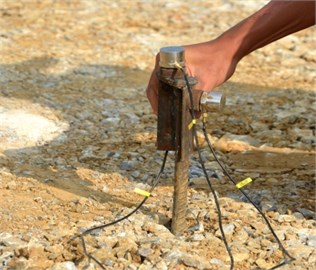
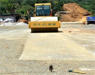
The range of the acceleration sensor is 5 g and its resolution is 0.0001 ms-2. Its installation method is described as follows: three mutually perpendicular steel plates are welded at one end of a steel bar with its diameter of 25 mm and length of 400 mm, then the steel bar is drilled into the subgrade surface, and finally the acceleration sensors on the magnetic base are stuck onto the steel plates (shown in Fig. 1). The acceleration sensors on different steel plates will test the vibration acceleration in three different directions, including vertical, longitudinal and transverse.
In order to ensure accurate and reliable testing results, the whole measurement equipment should be calibrated before testing. The sampling frequency is 200 Hz.
2.4. Testing method and data processing
The vibrating roller stops at a distance of 30 m from the testing point and waits for start prior to vibration test. When a commander informs the roller driver to drive to the testing point, the signal collection system will start to record vibration acceleration in the whole testing process. vibration frequency (28 Hz), amplitude (1.8 mm) and driving speed (3 km/h) are kept constant when the roller is driving. The roller will stop at about 2 m from the testing point.
Fig. 1Acceleration sensor installation
The test process is susceptible to influences of occasional factors of the field conditions and measurement system. To ensure stable and reliable testing data, each operating condition should be repeated 3-5 times. After each test, the data should be instantly analyzed till the vibration wave form is stable and repeatable. Field tests are shown in Figs. 2-4.
Fig. 2Limestone subgrade field vibration test
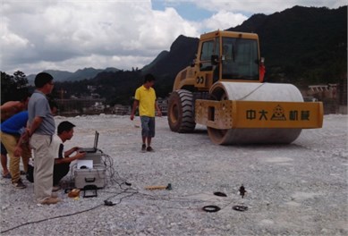
Fig. 3Fine-grained soil field vibration test
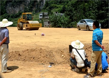
Fig. 4Coarse-grained soil field vibration test
The ground vibration data collection system gets the time travel curve of the vibration acceleration. The driving speed of the roller is fixed, so the time travel curve of vibration can be transformed to the curve of relation between vibration and distance according to the relation between the distance and time. The cycle peak of the acceleration should be extracted, and some abnormal values are filtered for smoothening to get the relation between the acceleration peak and distance.
3. Testing results analysis
3.1. Acceleration time domain and frequency domain analysis
Fig. 5 and Fig. 6 list the time travel curve and frequency spectrogram of the vibration acceleration of the rockfill subgrade, coarse-grained soil subgrade and fine-grained soil subgrade. Fig. 5 shows that the acceleration cycle peak will gradually increase when the roller approaches the testing point from far to near. The nearer the roller is to the testing point, the higher the acceleration will become.
Fig. 6 shows that the peak frequency of the rockfill subgrade, coarse-grained soil subgrade and fine-grained soil subgrade are 29.4 Hz, 23.1 Hz and 29.0 Hz. The peak frequency of the rockfill and fine-grained soil subgrade approximates the vibration frequency of the roller. The peak frequency of the coarse-grained soil subgrade is slightly less than the vibration frequency of the roller. Vibration of the roller is a low-frequency vibration source with fixed amplitude and cycle. In propagation of the simple harmonic wave, the vibration wave will reflect and retract among the soil particles, which will lead to different noise waves, but the main frequency is still the frequency of the vibration source. The main frequency received by the coarse-grained soil subgrade is slightly less than the frequency of the vibration source, but the mechanism is not specific and should be further studied.
Fig. 5Acceleration time travel curve
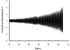
a) Rockfill subgrade
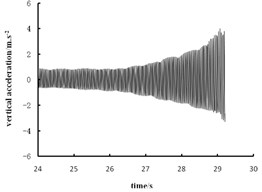
b) Coarse grained soil subgrade
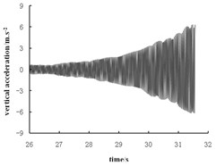
c) Fine grained soil subgrade
Fig. 6Acceleration frequency spectrogram
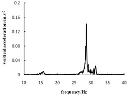
a) Rockfill subgrade
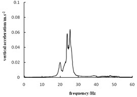
b) Coarse grained soil subgrade
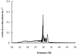
c) Fine grained soil subgrade
3.2. Vibration propagation characteristics of rollers
3.2.1. Comparison of vibration acceleration in different directions
The relation between vibration acceleration and distance of the rockfill subgrade in the vertical, longitudinal and transverse is shown in Fig. 7.
Fig. 7 shows that acceleration amplitude of longitudinal direction is maximal, and that of vertical and transverse are similar. With a decrease of distance, the vibration acceleration will increase. The vibration acceleration increases experiences two phases: initial vibration and acceleration increase. From a distance of 30 m to the range of 10-14 m, the vibration acceleration roughly keeps around the initial value in all the three directions. The initial value is about 0.6 m/s2 in longitudinal. The initial value is about 0.4 m/s2 and 0.3 m/s2 in vertical and transverse, which belongs to the initial vibration phase. The acceleration will gradually increase with the decrease of distance, and amplification grows larger on the acceleration increase phase. The vibration acceleration is more than 5 m/s2 in three directions when the test is completed. The distance for entering acceleration increase phase is different in three directions. The first is the longitudinal (distance of 14-15 m), followed by transverse (11-13 m) and vertical direction (10 m). The distance for entering the vibration acceleration increase phase can be called as the effective influence distance. The effective influence distance of the rockfill subgrade is 10-14 m. The vibration beyond the effective influence distance keeps a weaker initial value, while acceleration increases greatly with a decrease of distance within the effective influence distance.
Fig. 7Vibration propagation of rockfill subgrade
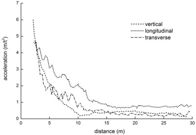
According to the wave theory [1], longitudinal wave, transverse wave and Rayleigh wave will be generated in the elastic half space under vibration. Longitudinal wave and transverse wave propagate in a semispherical manner while Rayleigh wave propagates in a circumferential direction (cylindrical surface). The components of the Rayleigh wave remain the same at various points on the half space surface, while those of the longitudinal wave and transverse wave attenuate according to a power function relation with the distance from the vibration source. Therefore, the influence of the body wave is within the near field while that of the Rayleigh wave is remote from the vibration source. The initial vibration value in Fig. 8 is caused by the Rayleigh wave. As a linear movement stabilization source, the vibrating roller generates both vertical vibration force and horizontal vibration force for pushing the vibration wheel forward. So, the longitudinal vibration is greater than transverse and vertical vibration. Under the same vibration strength, the horizontal vibration is more destructive to the structure than vertical vibration. When considering the environmental vibration hazards generated by the roller, more attention should be paid to the influences of the longitudinal on the structures.
Fig. 8Vibration comparison of different fillings
3.2.2. Vibration comparison of different filling subgrade
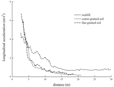
The relation between the longitudinal vibration acceleration and distance for different subgrade is shown in Fig. 8.
Fig. 8 shows that the initial acceleration of the rockfill subgrade is about 0.6 m/s2, while that of the coarse-grained soil subgrade and fine-grained soil subgrade is only about 0.2 m/s2. The distance for acceleration increases phase of rockfill subgrade is about 14 m, while that for the coarse-grained soil and fine-grained soil subgrade remains about 12 m. Of the three filler subgrades, the rockfill subgrade has the maximal vibration amplitude with a remotest effective influence distance, while fine-grained soil subgrade and coarse-grained soil subgrade have the similar vibration amplitude. In the near field (5 m from the vibration source), the vibration of coarse-grained soil subgrade is obviously stronger than that of fine-grained soil subgrade.
The vibration wave attenuation in propagation can be categorized as geometric damping and material damping types. Varied material damping attenuation leads to different vibration attenuation characteristics. The greater the filling strength and rigidity of subgrade is, the smaller the plastic deformation generated under stress. The wave absorption causes very little energy loss and generates the least damping attenuation, which leads to the slowest vibration attenuation and remotest propagation distance of rockfill subgrade. Compared with the rockfill subgrade, the strength and rigidity of the coarse-grained soil and fine-grained soil filling are smaller. Under stress wave, there is greater plastic deformation and more energy loss, which leads to larger material damping attenuation. In addition, Fig. 9 shows that in the near field (within 10 m), the vibration attenuation of the coarse-grained soil subgrade is faster than that of the fine-grained soil subgrade. This may be explained by the high porosity and low moisture content of the coarse-grained soil subgrade, which causes more energy loss of vibration wave in propagation.
4. Vibration attenuation law of rollers
For propagation and attenuation of vibration wave in the soil, Bornitz [21] proposed in 1931 the attenuation equation of the ground vibration when the vibration source acts on the soil surface:
where, is acceleration amplitude (m/s2) from the vibration source of ; is acceleration amplitude (m/s2) at the vibration source of ; is distance from the vibration source; is material damping attenuation coefficient; n is a constant and takes a value by different loads.
In the Eq. (1), reflects the energy consumption of the subgrade soil material damping to the vibration, and reflects geometric damping attenuation of vibration (including body wave and face wave). Based on this formula, many scholars study the ground vibration propagation and attenuation later.
According to the relevant literatures [19, 22], the vibration wave is composed of body wave and surface wave. The attenuation of mechanical vibration along the ground includes geometric damping attenuation and material damping attenuation. According to the propagation theory of vibration energy, the vibration attenuation caused by material damping is exponentially related to the distance, and the attenuation rate is related to the material damping attenuation coefficient (alpha). Geometric damping attenuation includes the attenuation of body wave and surface wave. The energy of surface wave is the main energy of subgrade surface vibration. Surface wave attenuates proportionally to distance -1/2. Because the body wave energy is less and its attenuation is faster, its effect is not considered. Combining the characteristics of roller, the parameters are selected. Considering the influence of roller vibration frequency [23] and a smaller initial value of vibration acceleration, the following formula can be get:
where, is acceleration at the distance of from the vibration wheel center on the ground (m/s2); k is initial acceleration beyond the effective influence distance (m/s2); is vibration frequency of vibrating roller (Hz); is energy absorption coefficient of subgratde soil (s/m); is Comprehensive influence factor;
The Eq. (2) is used for regressive fitting of the acceleration peak in the effective distance to get the parameter and .
The construction of high-power vibrating roller may damage the buildings around the road, the degree of which mainly depends on the vibration roller and type of the buildings. “Specification for Building Seismic Design (GB50011-2008)” regulates that the vibration acceleration peak of the grade 6, 7 and 8 seismic fortification intensity is 0.05 g, 0.1 g and 0.2 g. The bridges and culverts are the mostly affected by construction of the vibrating roller. Generally, the culvert is made of the steel reinforced concrete and can resist vibration well. Therefore, this paper will temporarily regard 0.2 g of the vibration acceleration peak as the vibration security standard and then calculate the vibration safety distance .
Therefore, the safety distance under different operating conditions is calculated according to the fitting parameters in the Eq. (2). The testing vibration frequency for this test is 28 Hz. The vibration testing data of the high-power vibrating roller on the rockfill subgrade and coarse-grained soil subgrade is fitted to get the fitting parameters, shown as the Table 4 and Fig. 9.
Table 4Fitting parameters of vibration acceleration attenuation
Filling type | Acceleration direction | Fitting parameter | (m) | |||
(s/m) | (m/s2) | |||||
Rockfill | Vertical | 14.16 | 9.1×10⁻³ | 0.4 | 0.9917 | 5.3 |
Longitudinal | 8.61 | 3.1×10⁻³ | 0.6 | 0.9309 | 8.7 | |
Transverse | 8.94 | 5.4×10⁻³ | 0.3 | 0.9329 | 5.5 | |
Coarse-grained soil | Vertical | 27.88 | 16.8×10⁻³ | 0.2 | 0.8973 | 4.3 |
Longitudinal | 36.54 | 21.6×10⁻³ | 0.2 | 0.9431 | 3.9 | |
Transverse | 49.82 | 15.9×10⁻³ | 0.2 | 0.9712 | 5.4 | |
Fig. 9Comparison of vibration fitting parameters
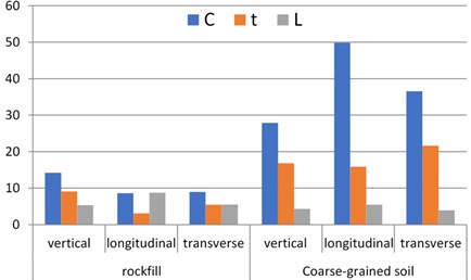
Table 4 shows that the correlation coefficient is more than or approximates 0.9, which indicates that the fitting of the Eq. (2) is correlated well, namely the Eq. (2) can better reflect the vibration attenuation law of the roller.
By analyzing the Fig. 9, the fitting parameters of the vibration acceleration are related to type of filling. Under the same vibration load, values of different fillings are different greatly. values of the rockfill subgrade will range from 8.61 to 14.16, that of the coarse-grained soil from 27.88 to 49.82. The comprehensive influence factor is associated with the roller and filling type.
The energy absorption coefficient represents attenuation rate of vibration. value of the coarse-grained soil subgrade is 2-7 times that of the rockfill subgrade, which indicates that the vibration absorption capability of the coarse-grained soil is stronger than that of the limestone filling. Compared with the limestone with greater strength and rigidity, the coarse-grained soil will be prone to plastic deformation under vibration. The generated plastic deformation consumes energy of partial stress wave, which leads to quicker vibration attenuation.
The vibration attenuation of the rockfill subgrade is slow and the generated vibration will affect a remote distance, so the safety distance of the rockfill subgrade is greater than that of the coarse-grained soil subgrade on the whole. The maximum L of the rockfill subgrade is 8.7 m while that of the coarse-grained soil subgrade is only 5.4 m.
5. Conclusions
Based on the study, the following conclusions can be drawn:
1) The peak frequency of the vibration waves is close to the vibration frequency of roller. The vibration acceleration will gradually increase with the decrease of distance. The increase process is divided into the initial vibration phase and acceleration increase phase. The distance for acceleration increase is from 10 m to 14 m. The range of the initial vibration is more than 30 m,
2) Vibration amplitude of longitudinal is more than that of vertical and transverse. When the environmental influence of the roller is evaluated, the longitudinal vibration will be mainly considered. Compared with the coarse-grained soil and fine-grained soil subgrade, the vibration acceleration attenuation of the rockfill subgrade is the slowest and the effective influence distance is the remotest,
3) Based on the wave theory and past research achievements, the vibration attenuation equation of the roller is proposed. The calculation results of the equation match well with the field-testing data.
References
-
Lombaert G., Degrande G., François S., Thompson D. J. Ground-Borne Vibration Due to Railway Traffic: a Review of Excitation Mechanisms, Prediction Methods and Mitigation Measures. Noise and Vibration Mitigation for Rail Transportation Systems. Springer Berlin Heidelberg, 2015.
-
Zhang T. W., Lamas Lopez F., Cui Y. J., et al. Development of a simple 2D model for railway track-bed mechanical behaviour based on field data. Soil Dynamics and Earthquake Engineering, Vol. 99, 2017, p. 203-212.
-
Wang L. Vibration characterization of fully-closed high speed railway subgrade through frequency: sweeping test. Soil Dynamics and Earthquake Engineering, Vol. 88, 2016, p. 33-44.
-
Kuo K. A., Papadopoulos M., Lombaert G., Degrande G. The coupling loss of a building subject to railway induced. Journal of Sound and Vibration, Vol. 442, 2019, p. 459-481.
-
Ren X. W., Wu J. F., Tang Y. Q., Yang J. H. Propagation and attenuation characteristics of the vibration in soft soil foundations induced by high-speed trains. Soil Dynamics and Earthquake Engineering, Vol. 117, 2019, p. 374-383.
-
Hwang J. H., Tu T. Y. Ground vibration due to dynamic compaction. Soil Dynamics and Earthquake Engineering, Vol. 26, Issue 5, 2006, p. 337-346.
-
Yao Z., Pan X., Jin Z., Zhang K., Zhang X. Vibration propagation of dynamic compaction in widening highway foundations. International Conference on Sustainable Civil Infrastructure, 2014, p. 54-61.
-
Tripathy G. R., Gupta I. D. Prediction of ground vibrations due to construction blasts in different types of rock. Rock Mechanics and Rock Engineering, Vol. 35, Issue 3, 2002, p. 195-204.
-
Zheng C., Ding X., Sun Y. Vertical vibration of a pipe pile in viscoelastic soil considering the three-dimensional wave effect of soil. International Journal of Geomechanics, Vol. 16, Issue 1, 2016, https://doi.org/10.1061/(ASCE)GM.1943-5622.0000529.
-
Ding G., Sun F., Fu H. Vibration propagation of diverse footings on saturated sand. International Journal of Civil Engineering, 2018, https://doi.org/10.1007/s40999-017-0279-3.
-
Liu H. M., Tao X. X., Zheng X. An explanation on mechanism of local amplification in attenuation of ground vibration from rail traffic in urban area. Applied Mechanics and Materials, Vol. 226, 2012, p. 228-4.
-
Auersch L., Said S. Attenuation of ground vibrations due to different technical sources. Earthquake engineering and Engineering Vibration, Vol. 9, Issue 3, 2010, p. 337-344.
-
Kim D. S., Lee J. S. Propagation and attenuation characteristics of various ground vibrations. Soil Dynamics and Earthquake Engineering, Vol. 19, Issue 2, 2000, p. 115-126.
-
Kenneally B., Musimbi O. M., Wang J., Mooney M. A. Finite element analysis of vibratory roller response on layered soil systems. Computers and Geotechnics, Vol. 68, 2015, p. 73-82.
-
Lamb H. On the propagation of tremers over the surface of an elastic solid. Philosophical Transactions of the Royal Society, Vol. 203, 1904, p. 1-42.
-
Gucunski N. Effects of multiple modes on Rayleigh wave dispersion characteristics. Journal of Geotechnical Engineering, Vol. 118, Issue 10, 1994, p. 1529-1543.
-
Auersch L. Technically induced surface wave fields, part I: measured attenuation and theoretical amplitude-distance laws. Bulletin of the Seismological Society of America, Vol. 100, Issue 4, 2010, p. 1528-1539.
-
Czech K. R., Gosk W. Measurement of surface vibration accelerations propagated in the environment. Procedia Engineering, Vol. 189, 2017, p. 45-50.
-
Senetakis K., Madhusudhan B. N., Anastasiadis A. Wave propagation attenuation and threshold strains of fully saturated soils with intraparticle voids. Journal of Materials in Civil Engineering, Vol. 28, Issue 2, 2016, p. 04015108.
-
Ekanayake S. D., Liyanapathirana D. S., Leo C. J. Attenuation of ground vibrations using in-filled wave barriers. Soil Dynamics and Earthquake Engineering, Vol. 67, 2014, p. 290-300.
-
Bornitz G. Über die Ausbreitung der von Großkolbenmaschinen erzeugten Bodenschwingungen in die Tiefe. Springer Berlin Heidelberg, 1931.
-
Emad K., Manolis G. D. Shallow trenches and propagation of surface waves. Journal of Engineering Mechanics, Vol. 111, Issue 2, 1984, p. 279-282.
-
Yang X. J. Attenuation of ground vibration caused by power machinery. Journal of Hunan University, Vol. 3, 1982, p. 12-18.
Cited by
About this article

This work was supported by Transportation Science and Technology Project of Guizhou Province (2013122005). This support is gratefully acknowledged.
