Abstract
A dynamic finite element model was established to characterize the motion state of the rotary steerable bottom hole assembly (RSBHA). Then the steering lateral force on bit was obtained after the motion equation was solved. The relation between the bit steering force and the pads offset pointing towards the high side direction of the borehole was gotten and the effects of the rotary speed on the bit lateral steering force were analyzed. Results showed that the near-bit stabilizer would contact the wellbore wall with the increasing of the pads offset, resulting in an inflection point presenting on the relation curve between the bit inclination force and the pads offset value. The larger pads offset value was, the more concentrated bit side cutting would be. Rotary speed had a small effect on time average of the bit lateral steering force but could enlarge the action range on both sides of the high side direction of the borehole.
1. Introduction
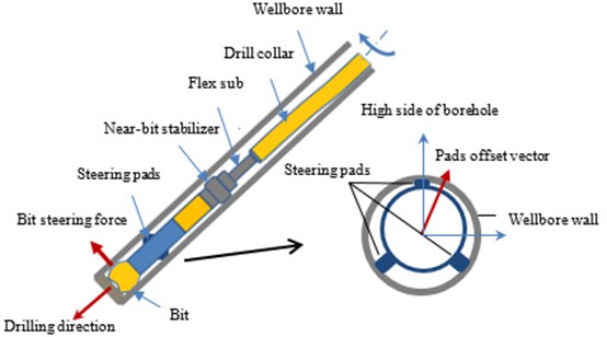
The bit lateral force is considered as a significant mechanical parameter of the bottom hole assembly (BHA) which affects the bit tendency in the case of drilling directionally [1-3]. It is commonly used to help engineers and scholars evaluate the drilling tendency qualitatively or quantitatively which was verified by the field test illustrating the evaluation criterion of the bit lateral force as valid [4-6]. It is especially the case for the push-the-bit rotary steerable bottom hole assembly (RSBHA) as shown in Fig. 1. With the near-bit expandable pads extending to the wellbore wall, a lateral steering force is generated on the bit which results in a bit side cutting. The force vector and the geometry offset at pads are two controlled variables in different steering principles [7].
Much work has been done on modeling and solving mechanical properties of BHA. Bai, et al. [8] developed the continuous beam theory to study the stress and deformation of BHA. And then Tang, et al. [9] derived the relation between the bit lateral steering force and its influencing parameters with this method aiming at push-the-bit RSBHA. Akgun & Apostal [10] and Panayirci, et al. [11] used the beam finite element model to estimate the bit lateral force. Note that the bit lateral force calculated above is a static value neglecting the effects of dynamic factors. However, it is more comprehensive to analyze the dynamic bit lateral steering force by considering the rotational state of RSBHA in the case of drilling directionally. Millheim, et al. [12] presented a 3D finite element algorithm and analyzed the effects of inclination and rotary speed on the bit lateral force. Results revealed both of these influencing factors had an impact on the directional force and the inclination force.
The finite element method is more suitable to deal with the physical model with the variable cross-section. For push-the-bit RSBHA, a flex sub with a smaller section radius and lower flexural rigidity exists between the near-bit stabilizer and the upper stabilizer. Therefore, the finite element method was applied to estimate the bit lateral steering force by solving the RSBHA motion equation. Various pads offset and different rotary speed were set up to analyze the variation characteristic of the bit lateral steering force which would help determine control instructions to meet the well path control goal.
2. RSBHA finite element model
The push-the-bit mode consists of two major sub-categories of driving mechanisms: one is applying dynamic push force from a rotating housing and the other is applying static push force from a non-rotating housing which is focused on in this paper. As Fig. 1 shows, the pads geometry offset will be formed when the steering pads extend out in a different degree with a resultant pushing force acting on the section plane. It can be treated as an eccentric stabilizer by considering the functions of steering pads. As the join of the flex sub and the stabilizer change the cross section, the RSBHA can be dispersed by a series of segmented, homogeneous and uniform-section beams bearing variable loads [13].
Fig. 1Directional drilling of push-the-bit RSBHA
2.1. Assumptions
1. Drill string is regarded as an elastic beam column.
2. The wellbore section is circular without borehole enlargement or reduction.
3. The upper end of RSBHA lies on the low side of the borehole and the bit is simply supported.
2.2. Analytical equations
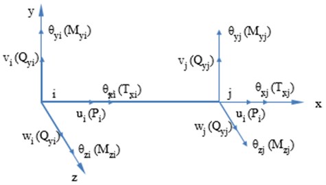
A simplified drill string element is shown in Fig. 2. The relevant parameters of the drill string element are divided into two categories: nodal displacement data and load parameters. In the finite element analysis, nodal displacements are generally taken as the basic unknown variables.
The nodal displacement vector of drill string element is expressed as:
where , and are the displacement of node in , and direction respectively; , and are the rotation angles of node in , and direction respectively; variables with subscript “” represent the displacement of node . The nodal force vector of drill string element is expressed as:
where is the axial force of node ; and are the shear forces of node in and -direction respectively; is the torque of node ; and are the bending moments of node in - plane and - plane respectively; variables with subscript “” represent the loads of node .
Fig. 2Drill string element
The generalized displacement vector of drill string element is depicted by:
where is the shape function matrix [14].
The generalized velocity and acceleration vector of drill string element can be expressed as:
where and are the nodal velocity and acceleration vector of drill string element.
The dynamic equation of drill string element can be obtained according to the Lagrange equation which is shown as:
where , and are the element kinetic energy, potential energy and dissipation function respectively:
where , are body force and surface force respectively; is the damping coefficient.
Eqs. (7), (8) and (9) taken into Eq. (6), and assembled by the drill string elements, the motion equation of RSBHA can be obtained as:
where , and are the generalized nodal displacement, velocity and acceleration matrixes in global coordinate system respectively; , and are the mass, damping and stiffness matrixes of RSBHA system in global coordinate system; is the generalized external force vector.
As for the constraint of wellbore, the interaction model between drill string and wellbore is used to deal with this problem where the contact forces are proportional to the penetration depth. Finally, Newmark method is taken to solve the dynamic motion equation of RSBHA [15].
3. Bit steering force analysis
As a vector, the pads offset can be set up flexibly under the necessity of achieving an expected directional tendency purpose such as building, dropping, azimuth increasing or reducing for push-the-bit rotary steerable tools. In this study case, we focus on the build-up mode where the pads offset points towards the high side direction of the borehole under different offset values and rotary speed conditions.
3.1. Basic parameters
Push-the-bit RSBHA configuration: 215.9 mm PDC bit+178 mm rotary steerable tool+213 mm stabilizer+127 mm flex sub+165.1 mm drill collar+212 mm stabilizer +165.1 mm drill collar. The concrete parameters are shown in Fig. 3.
Fig. 3Push-the-bit RSBHA Configuration
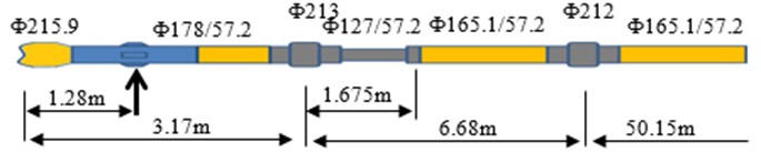
Drilling parameters: Rotary speed varies from 60 rpm to 180 rpm and the pads offset is set up in a range from 0.5 mm to 1.8 mm. WOB is 60 kN and drilling fluid density is taken as 1.27 g/cm3. The borehole is a slant hole with a 30-degree inclination.
3.2. Characteristics of the bit steering force
The inclination force and the azimuth force are two orthogonal components of the bit lateral steering force which points towards the high side direction (-direction) of the borehole and its lateral direction (-direction) respectively. According to the coordinate system established in this paper, a positive value of the inclination and the azimuth force represents that the inclination is built up and the azimuth is increased. We take the first three seconds of total simulation time to analyze the characteristics of the steering force.
3.2.1. Effects of the pads offset
We can obtain different responses of the bit lateral steering force through changing the pads offset value. Fig. 4 shows the dynamic bit lateral steering force when the pads offset is 0.5 mm, 1.0 mm and 1.5 mm respectively.
It is obvious that with the increase of the pads offset value, the time weight average of the inclination force goes up in a different degree where the force value attains a much higher level when the offset jumps from 1.0 mm to 1.5 mm than it from 0.5 mm to 1.0 mm. What’s more, with a lower fluctuation amplitude, when the pads offset is 1.0 mm and 1.5 mm respectively, the amplitude tends to be smaller. Whereas the azimuth force and the fluctuation amplitude nearly remains unchanged. The time weight average of the azimuth force is roughly the same when the offset varies from 0.5 mm to 1.0 mm, however, the value turns to be positive when the pads offset is taken as 1.5 mm. A bigger pads offset will change the bit walk tendency.
Fig. 4Bit dynamic lateral steering force under different kinds of pads offset
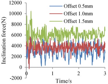
a) Inclination force
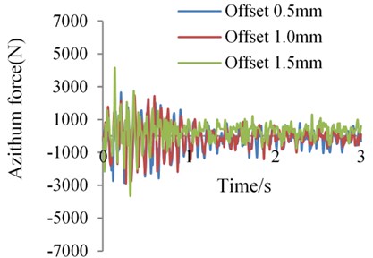
b) Azimuth force
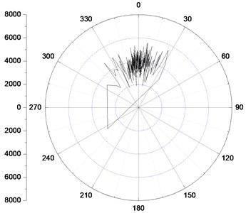
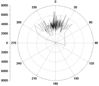
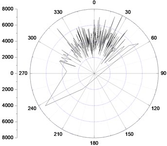
Fig. 5Bit lateral steering force distribution
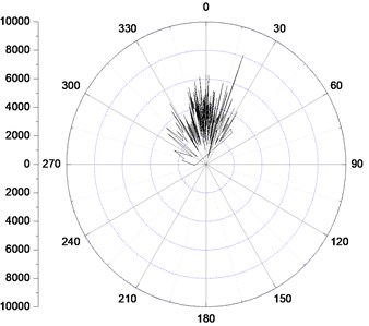
a) Offset is 0.5 mm
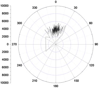
b) Offset is 1.0 mm
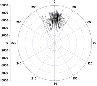
c) Offset is 1.5 mm
The polar diagram can clearly exhibit the distribution of the bit lateral steering force synthetized by the inclination and the azimuth force. As Fig. 5 shows, the circumferential coordinate stands for the tool face angle where figure zero points towards the high side of the bottom hole and the radial coordinate represents the size of the steering force vector. It will be more intuitive to make a comparison through the distribution of the bit lateral steering force.
When the offset is 0.5 mm, the direction of the bit lateral force varies from 330° to 30°. With the increasing of the offset, the pointing range gets shrunk towards the high side direction of the borehole with a thirty degree and twenty degree in 1.0 mm and 1.5 mm offset respectively. This tendency presents a more concentrated cutting function applied by the bit with a lower bit walk degree. From the perspective of the directional drilling, it is better to use a bigger pads offset to attain a quick orientation state especially at a lower borehole inclination where the bit walk is more obvious.
As it is a known steering parameter set up by engineers, it is better to establish the relation between the offset and the bit lateral steering force, which helps engineers determine the value of the offset to meet the directional drilling requirements. Table 1 shows the time weight average of the bit steering force under different pads offset values. A more intuitive relation is expressed through the diagram shown in Fig. 6.
Table 1Time weight average of the bit steering force
Pads offset (mm) | Inclination force (N) | Azimuth force (N) |
0.5 | 3139.62 | –127.27 |
0.8 | 3447.28 | –145.56 |
1 | 3760.28 | –135.76 |
1.2 | 4245.85 | –32.96 |
1.5 | 6126.43 | 300.71 |
1.8 | 8364.09 | 514.26 |
Fig. 6Relation of the bit steering force and the pads offset
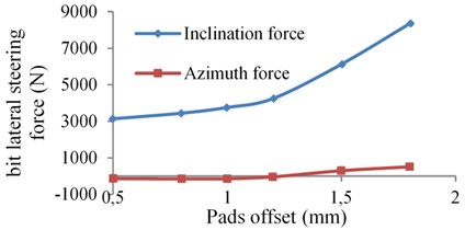
As Fig. 6 shows, the inclination force gradually increases with the pads offset when the offset is lower than 1.2 mm and azimuth force generally remains unchanged. However, the inclination force goes up rapidly and the azimuth force gradually grows to be a positive value when the offset is bigger than 1.2 mm. An inflection point turns out on the curve nearly at the offset value as 1.2 mm, indicating that a different stress state occurs.
Why there exists an inflection point? It can be explained by the change of displacement of the near-bit stabilizer in the borehole. Fig. 7 shows the near-bit stabilizer lateral movement in the section perpendicular to the borehole axis. The arc represents the maximum movement range of the near-bit stabilizer section centroid where the stabilizer section is shrunk as a point. It is obvious that almost no interaction generates between the near-bit stabilizer and the borehole wall when the offset is 1.0 mm, whereas, it has contacted and stuck on the wall when the offset is increased to be 1.2 mm and 1.5 mm respectively. Different stress state of the push-the-bit RSBHA is produced because a new fulcrum point is formed between the bit and the upper stabilizer. An equal size of the offset increment will need a larger pushing force applied by the steering pads and then the bit lateral steering force will also become much bigger. What’s more, the azimuth force will also change due to the contact of the near-bit stabilizer to the borehole wall, which results in a right hand bit walk tendency. The inclination and the azimuth force all change linearly with the increase of the pads offset on both sides of the inflection point. It is easy to get a fitting curve to characterize the relation between the force and the pads offset. It is helpful for engineers to understand how much the bit lateral steering force is when a certain pads offset value is given out.
Fig. 7Relation of the bit steering force and the pads offset
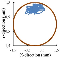
a) Offset is 1.0 mm
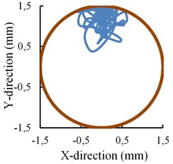
b) Offset is 1.2 mm
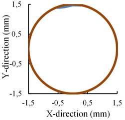
c) Offset is 1.5 mm
3.2.2. Effects of the rotary speed
As it is an important factor influencing the dynamic mechanical properties of BHA, it is necessary to study the effects of the rotary speed on the bit steering characteristics. Fig. 8 shows the bit lateral steering force under different rotary speed with a 1.0 mm pads offset value.
Fig. 8Bit lateral steering force distribution under different rotary speed
a) Rotary speed 60 rpm
b) Rotary speed 120 rpm
c) Rotary speed 180 rpm
As we can see, a wider spread on both sides of the high side direction of the borehole illustrating that the distribution of the bit steering force is more dispersed with the increase of the rotary speed. It indicates a more severe interaction between the bit and the borehole in the azimuth direction. What’s more, the steering force fluctuation amplitude becomes much larger when the rotary speed turns from 120 rpm to 180 rpm, which illustrates that a high speed will lead to the instability of the bit rotation, whereas, the amplitude is nearly the same when the rotary speed is 60 rpm and 120 rpm respectively.
Table 2 shows the time weight average of the bit lateral force under different rotary speed.
Table 2Time weight average of the bit lateral force under different rotary speeds
Rotary speed (rpm) | Inclination force (N) | Azimuth force (N) |
60 | 3718.43 | –129.21 |
90 | 3692.88 | –122.73 |
120 | 3680.70 | –118.39 |
150 | 3737.42 | –88.79 |
180 | 3744.04 | –72.95 |
As we can see from Table 2, the time weight average of the inclination and the azimuth force on the bit changes little with the increase of the rotary speed, though the fluctuation amplitude of the force has a bigger change. The bit side cutting direction remains unchanged in the circumferential coordinate system so that no specialized tool face change needs to maintain the original side cutting when the rotary speed gets changed. However, it is advised to take a suitable rotary speed rather than an excessive one to apply the directional drilling operation to maintain the stability of the bit.
4. Conclusions
The finite element method was adopted to establish the dynamic mechanical model of push-the-bit RSBHA simplified as the beam column which could disperse into various segmented, homogeneous beams bearing variable loads. Focus was put on the variation of the bit lateral steering force under the effects of the pads geometry offset and the rotary speed. Through the analyses above, some useful conclusions and suggestions were obtained: (1) with the increasing of the pads offset, the near-bit stabilizer would contact the wellbore wall, resulting in a different stress state for an extra fulcrum point being formed between the bit and the upper stabilizer; (2) a right hand bit walk tendency appeared more obvious when the larger interaction force between the near-bit stabilizer and the wellbore wall was acted; (3) the rotary speed had a small effect on the time average of the bit lateral steering force but could enlarge the action range on both sides of the high side direction of the borehole. (4) It is advised to take a bigger offset value and a suitable rotary speed within 120 rpm to apply the directional drilling operation because this combination will have a more concentrated bit side cutting and a bit motion stability.
References
-
Gaynor T., Chen D. C.-K. Making steerable bits: separating side-force from side-cutting. SPE Asia Pacific Oil and Gas Conference and Exhibition, Perth, Australia, 2004.
-
Zhang Y., Sameul R. Analytical model to estimate the directional tendency of point and push-the-bit BHAs. SPE Annual Technical Conference and Exhibition, Houston, Texas, USA, 2015.
-
Wang H., Guan Z. C., Shi Y. C., Liang D. Y. Study on build-up rate of push-the-bit rotary steerable bottom hole assembly. Journal of Applied Science and Engineering, Vol. 20, Issue 3, 2017, p. 401-408.
-
Birades M., Fenoul R. A microcomputer program for prediction of bottom hole assembly trajectory. SPE Drilling Engineering, Vol. 3, Issue 2, 1988, p. 167-172.
-
Shi Y. C., Guan Z. C., Zhao H. S., Huang G. L. A new method for build-up rate prediction of bottom-hole assembly in well drilling. Journal of China University of Petroleum, Vol. 41, Issue 1, 2017, p. 85-89.
-
Wang H., Guan Z. C., Shi Y. C., Liu Y. W., Liang D. Y. Drilling trajectory prediction model for push-the-bit rotary steerable bottom hole assembly. International Journal of Engineering, Transactions B: Applications, Vol. 30, Issue 11, 2017, p. 1800-1806.
-
Sugiura J. Optimal BHA design for steerability and stability with configurable rotary-steerable system. SPE Asia Pacific Oil and Gas Conference and Exhibition, Perth, Australia, 2008.
-
Bai J. Z., Huang H. Z., Liu Y. S. Three-dimensional analysis of bottom hole assembly by beam-column theory. Acta Petrolei Sinica, Vol. 10, Issue 2, 1989, p. 60-66.
-
Tang X. P., Su Y. N., Ge Y. H., Sheng L. M., Li T. J. BHA mechanical analysis for rotary steering drilling system. Mechanics in Engineering, Vol. 35, Issue 1, 2013, p. 12-15.
-
Akgun F., Apostal M. C. A finite element model for analyzing horizontal well BHA behavior. Journal of Petroleum Science and Engineering, Vol. 42, Issues 2-4, 2004, p. 121-132.
-
Panayirci H. M., Brands S., Houette O. Selection of optimum bottom hole assembly configuration using steering prediction modeling. Journal of Natural Gas Science and Engineering, Vol. 27, 2015, p. 757-762.
-
Millheim K. K., Apostal M. C. The effect of bottom hole assembly dynamics on the trajectory of a bit, journal of petroleum technology. Vol. 33, Issue 12, 1981, p. 2323-2338.
-
Lian Z. H., Zhang Q., Lin T. J., Wang F. H. Experimental and numerical study of drill string dynamics in gas drilling of horizontal well. Journal of Natural Gas Science and Engineering, Vol. 27, 2015, p. 1412-1420.
-
Di Q. F., Wang M. J., Hu Y. B., Zhao Y. D., Zhu W. P., Wang W. C. Effect of flex sub’s position on bottom hole assembly with rotary steering tool. Journal of China University of Petroleum, Vol. 36, Issue 5, 2012, p. 84-88.
-
Wang H., Guan Z. C., Shi Y. C., Chen W. Q., Liu Y. W., Zhang B., Liang D. Y., Wang X. H. Modeling and analyzing the motion state of bottom hole assembly in highly deviated wells. Journal of Petroleum Science and Engineering, Vol. 170, 2018, p. 763-771.
About this article

This paper is supported by the National Science and Technology Major Project (2016ZX05022-002), the Fundamental Research Funds for the Central Universities (16CX06035A, 17CX06016) and the National Natural Science Foundation of China (No. 51704320).
