Abstract
The article presents an extended summary regarding the impact of rail damage on vibration waveforms and vibroacoustic spectrum images of vibrations. The analyzed example is based on the passage of the train depot – passenger train on a selected railway line. A short summary of the analyzed research problem is also presented.
1. Introduction
There are two basic types of structural vibration: steady-state vibration caused by continually running machines such as engines, and transient vibration caused by a short-duration disturbance such as train passing over an expansion joint in a rail. The major source of railway rolling vibration is the structural vibration of the wheel and rail which is generated by the combination of small-scale undulations on the wheel and rail contact surfaces.
Fig. 1Schematic diagram of how rolling noise is generated by the wheel/rail interaction and radiated by the wheel, the rail and the sleepers [9]
![Schematic diagram of how rolling noise is generated by the wheel/rail interaction and radiated by the wheel, the rail and the sleepers [9]](https://static-01.extrica.com/articles/20232/20232-img1.jpg)
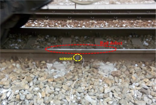
In the case of this research phenomenon, two measuring points were analyzed and located in Silesia region. Weather conditions prevailing on a given day were –5 degrees Celsius. Sampling with a single-axis sensor mounted was 42000 Hz. A characteristic feature of the selected measurement points was the finding of damage on the rail as shown in the below photograph (Fig. 2), differences in the waveform and vibration spectra in comparison to a healthy rail section – in this case the second sensor was located 5.4 m from the damage.
The maximum permissible wear of the rail head type UIC60, S49 and other types of rails weighing over 49 kg/m in main tracks is:
- main and primary lines – 12 mm,
- secondary lines – 14 mm,
- local meaning line – 16 mm,
- in side tracks of all line categories – 16 mm.
Fig. 2Area of Rail damage – damage to the running surface and sensor assembly
2. Research and results
The result of observation and registration of vibration acceleration. The vibrating signal is the carrier of information about the state, changes or process to which the considered physical system or technical system is subject. The vibroacoustic signals have the largest information capacity and allow observation of changes in a wide frequency band. Many measurement problems can be considered at the general level of the signal, treating the signal as a whole during observation. They can be considered in the areas of amplitude, time and frequency. In the case of vibrational phenomena of a random nature, the recorded signals will be non-stationary, which requires observation of the signal distribution simultaneously in the time and frequency domains. The subject of the analysis are railway depots moving on the route during the scheduled journey. However, rail damage resulting from the wear process will affect the final vibroacoustic image obtained. In sum, the measurements from two sensors were presented – the first named Ai3 located at the damaged part of the track and the second one located 5.4 meters from the damage (Ai2).
In the analyzed example, ELF 2 (34WEa) is an elaborated version of the electric traction unit type ELF, the need for the manufactured rail vehicles to meet the technical specifications for interoperability caused that from 2016 Pesa ceased to sell ELF type stores to ELF II different from the predecessor, among others compliance with these requirements. The arrangement of the Bo'2'Bo' axles and the possible maximum speed of 160 km/h. Another axle layout possible to meet on Polish tracks in the case of ELF/ELF 2 is Bo'2'2'Bo'; Bo'2'2'2'Bo'; Bo'2'Bo'2'2'; Bo'2'2'2'Bo'; Bo'2'Bo'2'Bo'2'Bo' and Bo'2'2'Bo' + 2'2'2'Bo. The braking system used in this composition is Knor-Bremse, the driving trolley of PESA production is 27MNd and there is no intermediate trolley with 2.7 m spacing. The intermediate PESA construction trolley is 40 and with a 3 m wheelbase. Axial gear GCM type 275 SO/549.
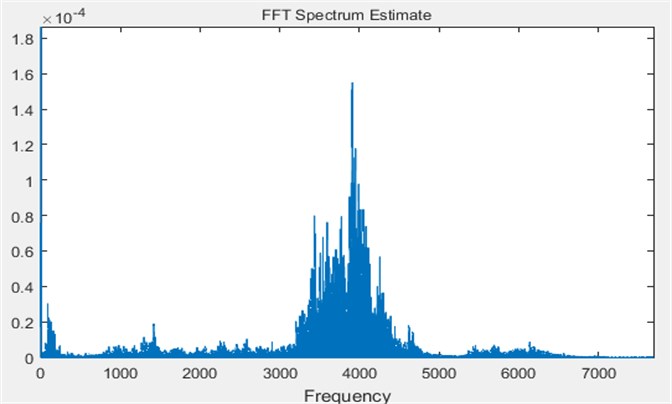
Fig. 3. A comparison of two waveforms for the sensor Ai2 (blue color) and Ai3 (purple color) is presented. Differences in amplitude for the two signals can be seen. In contrast, Fig. 4 and Fig. 5 show FFT Spectrum Estimate and for the signal from the sensor Ai2 a gain for frequencies from 50 Hz can be observed, decreasing until reaching 500 Hz. In the case of the signal from the Ai3 sensor the situation is different, and the amplification of the signal takes place around the frequency of 4000 Hz.
Fig. 3Vibration waveforms – blue color sensor Ai3, violet color sensor Ai2
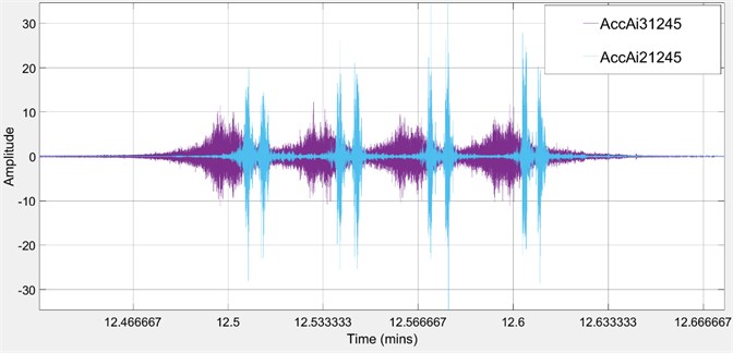
Fig. 4Spectral analysis of signals – signal from sensor Ai2
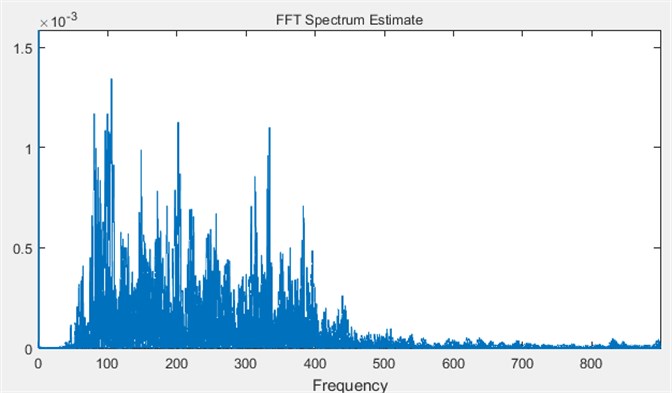
Fig. 5Spectral analysis of signals – signal from sensor Ai3
3. Conclusions
The article is only a summary of the extended analysis of the impact of rail damage on the vibroacoustic image. The ultimate goal of the study is to determine the propagation properties of vibrations occurring in the railway track for further analysis and concept of the train support system as well as identification of railway compositions based on vibroacoustic images.
The results, despite the slight damage to the rail, indicate a large difference in signal waveforms as well as in the image of the signal spectrum. It notices the amplification of the signal from the Ai3 sensor located near damaged place where the frequency oscillated around 4000 Hz, while the spectral analysis of the signal for the Ai2 sensor located 5.4 m away to the damage indicates oscillating values in the range from 50 to 500 Hz.
References
-
Cheli F., Corradi R. On rail vehicle vibrations induced by track unevenness: Analysis of the excitation mechanism. Journal of Sound and Vibration, Vol. 330, 2011, p. 3744-3765.
-
Hall L. Simulations and analyses of train-induced ground vibrations in finite element models. Soil Dynamics and Earthquake Engineering, Vol. 23, Issue 5, 2003, p. 403-413.
-
Picoux B., Le Houedec D. Diagnosis and prediction of vibration from railway trains. Soil Dynamics and Earthquake Engineering, Vol. 25, 2005, p. 905-921.
-
Siergiejczyk M., Paś J., Rosiński A. Issue of reliability-exploitation evaluation of electronic transport systems used in the railway environment with consideration of electromagnetic interference. IET Intelligent Transport Systems, Vol. 10, Issue 9, 2016, p. 587-593, https://doi.org/10.1049/iet-its.2015.0183
-
Młyńczak J., Burdzik R., Celiński I. Remote monitoring of the train driver along with the locomotive motion dynamics in the course of shunting using mobile devices. Dynamical System Control and Stability, 2015, p. 411-422.
-
Burdzik R., Nowak B., Młyńczak J., Deuszkiewicz P. Analysis of the detection and crossing signaling system in safety terms. Diagnostyka, Vol. 17, Issue 4, 2016, p. 65-72.
-
Młyńczak J., Burdzik R., Celiński I. Research on dynamics of shunting locomotive during movement on marshalling yard by using prototype of remote control unit, dynamical systems: theoretical and experimental analysis. Springer International Publishing, 2016, p. 279-292.
-
Burdzik R., Nowak B. Identification of the vibration environment of railway infrastructure. Procedia Engineering, Vol. 187, 2017, p. 556-561.
-
Thompson D. J., Jones C. J. C. A review of the modelling of wheel/rail noise generation. Journal of Sound and Vibration, Vol. 231, Issue 3, 2000, p. 519-536.
Cited by
About this article

Supported by Project “Support for R&D in Enterprises” WND-RPSL.01.02.00-24-06H2/16-002.
