Abstract
Bearing is widely used in the rotating machinery and prone to failure due to the harsh working environment. The bearing fault-induced impulses are weak because of poor background noise, long vibration transmission path, and slight fault degree. Therefore, the bearing fault detection is difficult. A novel adaptive stochastic resonance method based on multi-agent cuckoo search algorithm for bearing fault detection is proposed. Stochastic resonance (SR) is like a nonlinear filter, which can enhance the weak fault-induced impulses while suppressing the noise. However, the parameters of the nonlinear system exert an influence on the SR effect, and the optimal parameters are difficult to be found. Multi-agent cuckoo search (MACS) algorithm is an excellent heuristic optimization algorithm and can be used to search the parameters of nonlinear system adaptively. Two bearing fault signals are used to validate the effectiveness of our proposed method. Three other adaptive SR methods based on cuckoo search algorithm, particle swarm optimization or genetic algorithm are also used for comparison. The results show that MACS can find the optimal parameters more quickly and more accurately, and our proposed method can enhance the fault-induced impulses efficiently.
Highlights
- Adaptive stochastic resonance (SR) based on multi-agent cuckoo search (MACS) is effective for weak bearing fault detection.
- MACS can find the better SR parameters in same max iteration or same calculation time.
- Both of SR parameters H and K affect the SR effect.
1. Introduction
Bearing, which can support the rotating parts, is among the most widely used components in rotating machinery. Its failure is a common cause of machine breakdown as the harsh working environment, which can lead to tremendous economic losses and even cause disasters [1]. Earlier the bearing failure is discovered, more time people can take to avoid the unnecessary losses. However, the fault-induced impulses are weak due to the poor background noise, the long vibration transmission path, and the slight fault degree. Some methods have been proposed to detect the bearing failure [2-4]. For example, Sawalhi et al. [2] combined minimum entropy deconvolution with spectral kurtosis for rolling bearing failure. Smith et al. [3] proposed a simple spectral kurtosis-based approach for selecting the best demodulation band to extract bearing fault-related impulses from vibration. Mishra et al. [4] diagnosed bearing fault under slow speed operation by wavelet de-noising. However, the bearing fault-induced impulses are too weak and submerged in the strong background noise. Although much work has been done, there are still many shortcomings in bearing fault detection.
Stochastic resonance (SR) is a special physical phenomenon that the weak low-frequency signal is enhanced when the mixture of the weak signal and noise are inputted into a proper nonlinear system. The phenomenon means that noise can be utilized for the weak signal enhancement under certain circumstances. Since SR was proposed by Benzi et al. in 1981 [5], it has been studied and applied in many fields such as bioengineering [6], medical equipment [7], energy engineering [8] and so on. According to adiabatic approximation theory, the traditional SR only can deal with the low-frequency signal (the frequency is smaller than one) [9]. However, the bearing fault signal is a high-frequency signal (fault characteristic frequency is usually larger than one) and cannot be processed by the traditional SR. To solve the problem, researchers have proposed some methods such as re-scaling frequency SR [10], adaptive step-changed SR [11] and parameter normalized SR [12]. These methods can transform the high-frequency signal into a low-frequency signal that can be processed by the traditional SR. Because parameter normalized SR is simple and comprehensible, it will be used in this paper.
The parameters of the nonlinear system have a big influence on the SR effect. For example, the two parameters of the bi-stable system determine the barrier height. If the barrier is too high, it will be difficult for the particle to transfer from one potential well to another, and the bi-stable SR will not be triggered. If the barrier is too low, the effect of SR is not obvious. Heuristic optimization algorithms can search the optimal parameters of SR easily and have been applied in adaptive SR. For example, Chi et al. [13] used an adaptive SR based on cuckoo search algorithm for bearing fault diagnosis. López et al. [14] applied the underdamped SR based on particle swarm in weak signal detection. Qiao et al. [15] proposed an adaptive unsaturated bi-stable SR based on the genetic algorithm for mechanical fault diagnosis. However, these algorithms have relatively long computing time and their local optimization accuracies are insufficient. Multi-agent cuckoo search (MACS) algorithm applies the multi-agent strategy to cuckoo search (CS) algorithm and is a more efficient algorithm. In this paper, an adaptive SR based on MACS is proposed for bearing fault detection.
The rests of this paper are arranged as follows. Section 2 will analyze the bi-stable SR theory, the SR implements for the discrete signal and the evaluation of SR effect. Section 3 will introduce MACS and propose the adaptive SR based on MACS for bearing fault detection in detail. Section 4 will validate our proposed method by two bearing fault signals. Finally, Section 5 will provide conclusions.
2. Stochastic resonance theory
2.1. Bi-stable stochastic resonance
Bi-stable SR phenomenon is described as follows: a particle is driven by a weak driving signal and a noise in the bi-stable system, and then the weak oscillation is enhanced with the assistance of the noise. Such a phenomenon can be illustrated by Langevin Equation (LE) as:
where and are the amplitude and frequency of the driving signal. is Gaussian white noise (GWN) with noise intensity . is the standard GWN with zero mean and unit variance.
Fig. 1Sketch map of the bi-stable potential function Ux
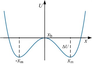
is the bi-stable potential function as shown in Fig. 1. and are the potential parameters, and , . It is obvious that the bi-stable potential function has two minimums which are located at and a potential barrier which is located at 0 with the height .
Thus, Eq. (1) can be rewritten as:
Supposing that and , Eq. (2) can be rewritten as:
Because both parameters of the bi-stable system are transformed into one, it is called parameter normalized transformation of SR. After the transformation, the driving frequency reduces times. Thus, the high-frequency signal can be transformed into a low-frequency signal by the transformation with the appropriate parameters (, ). The transformed signal will satisfy the limitation of the traditional SR.
2.2. SR implement for discrete signal
The collected vibration signal is discrete and contains weak fault characteristic signal and strong noise. Let denote the vibration signal. For a discrete signal , Eq. (3) can be solved by the five-order Runge-Kutta algorithm as:
where is the SR output. is the amplitude factor. is the integral step.
2.3. Evaluation of SR effect
A criterion is needed to evaluate the SR effect. Some indexes have been proposed such as approximate entropy [11], signal-to-noise ratio (SNR) [16], local signal to noise ratio (LSNR) [13] and weighted power spectrum kurtosis (WPSK) [17]. Because of the precise definition and easy application, LSNR will be used as the evaluation criterion:
where is the power of the frequency . is the power in frequency domain . Larger the LSNR is, better the signal is.
Fig. 2 shows the output LSNR with the increase of noise intensity under different low driving frequencies without transformation. With the increase of , the input LSNR decreases while the output LSNR increases at first and then decreases. Thus, the noise improves the SR output before the output LSNR reaches the maximum. Also, with the increase of the driving frequency, LSNR becomes smaller and smaller. It means that SR without transformation is effective for the low-frequency signal but bad for the high-frequency signal.
Fig. 2Output LSNR vs. D under different driving frequencies without transformation (fs= 10 Hz, signal length n= 104, A= 0.2, K= 1, H=1/fs=0.1, and ∆fN= 20 Hz)
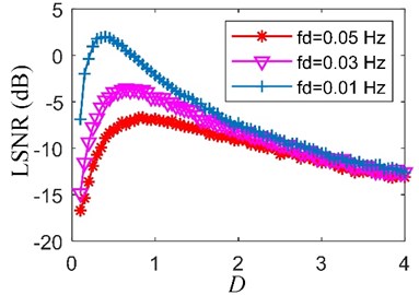
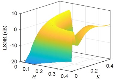
Fig. 3 shows the output LSNR with the variation of amplitude factor and integral step . Output LSNR varies with the change of parameter and . Larger the output LSNR is, better the parameter and are. However, the 3D surf in Fig. 3 is complicated. It is difficult to find the optimal parameter and . Therefore, a heuristic optimization algorithm is needed to find the optimal parameters.
Fig. 3Output LSNR vs. joint amplitude factor H and integral step K (fs= 6000 Hz, signal length n= 104, A= 1, fd= 30 Hz, D= 2 and ∆fN= 20 Hz)
3. Multi-agent cuckoo search algorithm
3.1. Cuckoo search algorithm
Cuckoo search (CS) algorithm is a new heuristic optimization algorithm and has been used in many fields [13, 18-20]. It simulates the parasitic reproductive strategy of cuckoos: the solutions are seen as cuckoo eggs, the optimal solution which has the optimal fitness as the optimal cuckoo egg, the feasible region as the search zone of the cuckoos. Three hypothetical rules are set as follows:
• A cuckoo only lay an egg at a time and dump it in a nest randomly.
• The current best egg should be kept to the next generation.
• The nest number is fixed. The host birds should find some cuckoo eggs with a probability , and these eggs will be replaced with new eggs.
When generating the new candidate solutions , the update by Lévy flights is performed as [19]:
where is the th solution of the th generation. is the step-size scale. is the best solution of the th generation. and obey the Gaussian distribution. is the standard gamma function. is the number of the solutions. 1.5 is a constant.
3.2. Multi-agent cuckoo search algorithm
CS is an excellent algorithm. However, it lacks the communication among the populations and knowledge learning of the cuckoos, which limits the performance of CS. We regard the cuckoos as intelligent agents. These agents can communicate with others and learn the knowledge. Thus, a new improved CS is proposed called multi-agent cuckoo search (MACS) algorithm. Two operations are designed to realize these behaviors. They are the competitive cooperation operation for communication and the self-learning operation for knowledge learning.
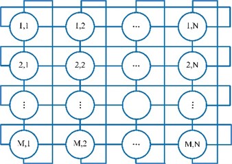
A multi-agent system should be constructed at first. Fig. 4 shows a multi-agent system with the Von Neumann structure. It contains × circles. Each circle represents a cuckoo. For a cuckoo, other cuckoos that connected with it by the lines are regarded as its neighborhoods. Let denote the cuckoo in th row and th column. Its neighborhoods are , , , and :
Fig. 4The multi-agent system with Von Neumann structure
Cuckoo only communicates with its neighborhoods by competitive cooperation operation. Supposing is the best neighborhood of . Competitive cooperation operation is performed only when the fitness of is better than . The operation can be described as:
where is the new cuckoo. is a random number that obeys the (–1, 1) uniform distribution. is the crossover probability. is a random number that obeys the (0, 1) uniform distribution. is the Heaviside function:
Only the current best cuckoo can learn knowledge through self-learning operation. Supposing is the current best cuckoo. Number of cuckoos are produced in a narrow range by Eq. (10). If the fitness of the produced best cuckoo is better than , the produced best cuckoo will replace . Otherwise, will not be changed:
where is the local search radius. is a random number that obeys the uniform distribution.
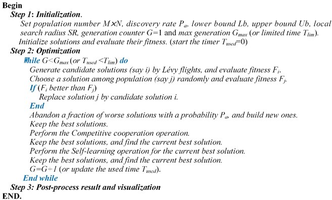
The simple pseudo-code of the MACS algorithm can be provided as shown in Fig. 5.
Fig. 5Pseudo-code of the MACS algorithm
3.3. The proposed adaptive SR for bearing fault detection
For the deterministic input signal, SR output depends on the parameters and according to Eq. (4). However, the optimal parameters and are different to be found. In the proposed adaptive SR, MACS is used to search the optimal parameters and . LSNR is used as the evaluation criterion of the SR effect. For the bearing fault detection, the detailed steps are stated as follows:
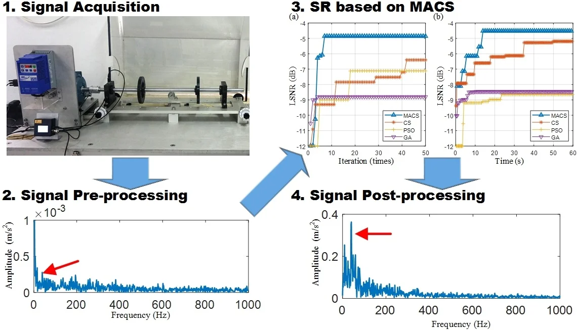
Step 1: Bearing vibration signal acquisition. Longer the vibration transmission path is, weaker the impact signal is. When acquiring the bearing vibration signals, the sensors should be near the bearings.
Step 2: Bearing vibration signal pre-processing. Some common techniques are used to preprocess the bearing vibration signal. Resonance demodulation is one of the most pre-processing technologies. Resonance band can be chosen by kurtogram, spectral kurtosis or visual identification [3, 21]. Visual identification is selected in this paper. The envelope signal is obtained by the conventional Hilbert transform method. The envelope signal contains not only the fault-induced impulses but also other known signals such as the shaft rotation signal. These known signals, especially whose frequencies are lower than the frequency of the impulses, are harmful to SR effect. Thus, these signals should be removed by spectral editing. The envelope signal is a unipolar signal, which is worse than the bipolar signal for SR effect improvement [22]. High-pass filtering is used to transform the envelope signal into a bipolar signal and filter some low frequencies which are harmful to the SR effect. Through the pre-processing, the preprocessed signal is obtained.
Step 3: Parameter initialization and optimization by MACS. Intervals of parameters (, ) and other related parameters are set. MACS is used to search for the optimal parameters (, ) which may solve Eq. (11):
Step 4: Signal post-processing. The optimal parameters (, ), optimal SR output and its corresponding maximum LSNR are collected.
4. Experimental validations
To verify the feasibility of our proposed method, two bearing preset failure tests are carried out through the test rig as shown in Fig. 6. The test rig consists of three parts: the power and control part, the bearing fault simulation part and the data acquisition part (not shown). The power and control parts are composed of a three-phase asynchronous motor (supply the power), a motor controller (control the motor speed) and a speed indicator (display the real-time speed of the motor). The bearing fault simulation part consists of two deep groove ball bearings (support the shaft), an optical shaft (supply the radial load for the bearings) and two flywheels (also supply the radial load). In order to realize the power transmission, the coupler should connect the motor to the shaft. The data acquisition part is composed of vibration acceleration sensors, a data acquisition card and a software (display and storage the data).
Fig. 6Bearing fault simulation test rig
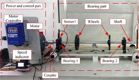
The bearing type is ER-12K, and its main dimensions are shown in Table 1. The preset faults are the inner-race fault (a groove with 0.5 mm width in the center of the inner race) and the rolling element fault (a deep groove with 0.5 mm width in one of the rolling elements). The fault bearing is located at bearing 1 as shown in Fig. 6. Vibration signals are collected by sensor 1. Sampling frequency is 12800 Hz, and sampling time is 0.5 s. Adaptive SR methods based on MACS, CS, particle swarm optimization (PSO) and genetic algorithm (GA) are used to process the bearing vibration signals for comparison. The parameters of these optimization algorithms are set as shown in Table 2. The parameters of bi-stable SR are set as and . is set as 50 Hz.
Table 1Main dimensions of bearing ER-12K
Number of rolling elements | Ball diameter (inch) | Pitch diameter (inch) | Contact angle (°) |
8 | 0.3125 | 1.318 | 0 |
Table 2Algorithm parameter setting
Algorithms | Parameters |
MACS | Population size 6×6, discovery rate 0.25, step-size scale 0.35, crossover probability 0.5, local search radius 0.05, number 25 |
CS | Population size = 50, discovery rate 0.25, step-size scale 0.35 |
PSO | Population size = 100, intertia coefficient = 1, damping ratio of inertia coefficient = 0.99, personal acceleration coefficient = 5, social acceleration coefficient = 10 |
GA | Population size = 100, crossover percentage = 0.7, extra range factor for crossover = 0.4, mutation percentage = 0.3, mutation rate = 0.1 |
4.1. Bearing inner-race fault detection
The bearing outer race fault signal is analyzed firstly. According to the main dimensions of bearing ER-12K in Table 1 and the real motor speed (19.922 r/s), the fault feature frequency is equal to 98.582 Hz. The bearing signal is preprocessed by the resonance demodulation. The signal is filtered by minimum-order Butterworth band-pass filter with pass-band [1500, 5000] Hz. The envelope signal is obtained by the Hilbert transform. The envelope signal and its spectrum are shown in Fig. 8(a). Some known frequencies that are lower than like the frequency 2 and 3are bad for the SR effect, and they will be removed by the spectral editing. It is obvious that the envelope signal is a unipolar signal, which is worse than the bipolar signal for the SR effect [22]. Thus, the minimum-order Butterworth high-pass filter with stop-band [0, 5] Hz is used to transform the unipolar envelope signal to a bipolar signal. After pre-processing, the preprocessed signal is obtained as shown in Fig. 8(b).
Then, the preprocessed signal is processed by the SR methods based on MACS, CS, PSO and GA respectively. Max iterations (50 iterations) and limited time (60 seconds) of calculation are set as the termination conditions of the four optimization algorithms respectively. The fitness convergence curves and final optimization results are shown in Fig. 7 and Table 3. We can see that the final LSNR of SR output based MACS is the biggest among the four algorithms under both termination conditions.
Fig. 7The fitness convergence curves of the four algorithms for the inner-race fault signal
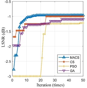
a) Max iteration = 50 times
b) Limited time = 60 s
Therefore, the adaptive SR based on MACS is the best among the four methods. The optimal SR output ( 0.290, 94.398) and its spectrum are shown in Fig. 8(c). The fault feature frequency is enhanced obviously. Thus, our proposed method is effective for bearing fault detection.
Table 3Optimization results of the four algorithms and related parameters for the inner-race fault signal
Algorithms | Max iterations = 50 times | Limited time = 60 s | ||
LSNR (dB) | LSNR (dB) | |||
MACS | –0.961 | [0.290, 94.352] | –0.960 | [0.290, 94.398] |
CS | –1.001 | [0.284, 93.965] | –0.961 | [0.290, 94.652] |
PSO | –1.222 | [0.277, 99.096] | –1.200 | [0.297, 89.445] |
GA | –1.097 | [0.264, 96.203] | –1.243 | [0.195, 130.002] |
Fig. 8Analysis results for the inner-race fault signal
a) Envelope signal and its spectrum
b) Preprocessed signal and its spectrum
c) SR output and its spectrum
4.2. Bearing rolling element fault detection
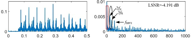
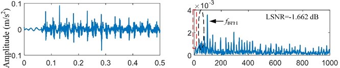
The fault-induced impulses in bearing rolling element fault signal are weaker than that in bearing inner-race fault signal. Then, the bearing rolling element fault signal will be analyzed. According to the main dimensions of bearing ER-12K in Table 1 and the real motor speed (19.922 r/s), the fault feature frequency is equal to 39.650 Hz. The bearing signal is preprocessed by the resonance demodulation. The signal is also filtered by minimum-order Butterworth band-pass filter with pass-band [1500, 5000] Hz, and the envelope signal is also obtained by the Hilbert transform. The envelope signal and its spectrum are shown in Fig. 10(a). It is obvious that the frequency is very weak and submerged in the heavy noise. The envelope signal is a unipolar signal, which is worse than the bipolar signal for the SR effect [22]. Then, the minimum-order Butterworth high-pass filter with stop-band [0, 5] Hz is used to transform the unipolar envelope signal to a bipolar signal. After pre-processing, the preprocessed signal is obtained as shown in Fig. 10(b).
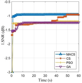
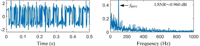
Then, the preprocessed signal is also processed by the SR methods based on MACS, CS, PSO and GA respectively. Max iterations (50 iterations) and limited time (60 seconds) of calculation are set as the termination conditions of the four optimization algorithms respectively. The fitness convergence curves and final optimization results are shown in Fig. 9 and Table 4. In Fig. 9, the convergence curve of MACS is steep in the early stage of optimization, which means that the MACS converges quickly. The final LSNR of SR output based MACS is the biggest among the four algorithms under both termination conditions. Therefore, the adaptive SR based on MACS is the best among the four methods. The optimal SR output ( 2.350, 58.986) and its spectrum are shown in Fig. 10(c). The fault feature frequency is enhanced obviously. Thus, our proposed method can enhance the weak signal submerged in the strong noise.
Fig. 9The fitness convergence curves of the four algorithms for the ball fault signal
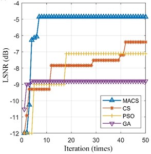
a) Max iteration = 50 times
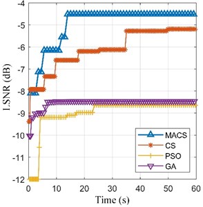
b) Limited time = 60 s
Table 4Optimization results of the four algorithms for the ball fault signal
Algorithms | Max iterations = 50 times | Limited time= 60 s | ||
LSNR (dB) | LSNR (dB) | |||
MACS | –4.855 | [1.498, 40.379] | –4.514 | [1.350, 58.986] |
CS | –6.401 | [1.609, 27.523] | –5.191 | [1.380, 70.745] |
PSO | –7.115 | [1.650, 27.523] | –8.644 | [0.240, 263.966] |
GA | –8.800 | [1.612, 11.193] | –8.462 | [0.215, 293.586] |
Fig. 10Analysis results for the rolling element fault signal
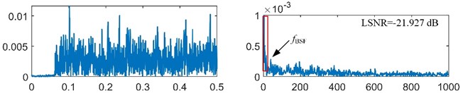
a) Envelope signal and its spectrum
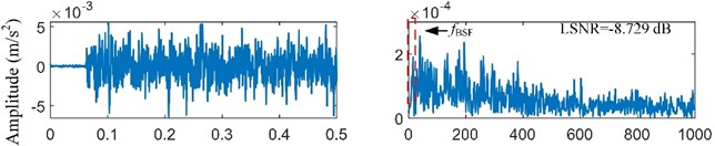
b) Preprocessed signal and its spectrum
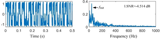
c) SR output and its spectrum
5. Conclusions
In this paper, we propose an adaptive SR based on MACS for bearing fault detection. Two bearing fault signals are used to validate our proposed method, and three adaptive SR methods based on CS, PSO, or GA are compared with our proposed method. The conclusions are drawn as follows: (1) Both of parameters and affect the SR effect; (2) MACS can find the best parameters of SR in the same max iteration or the same limited calculation time among the four methods; (3) Our proposed method is effective for bearing fault detection especially when the fault is weak.
However, the proposed adaptive SR based on MACS only can enhance the single effective frequency component. Other effective frequency components may be filtered. Thus, the detection of the multi-frequency signal should be researched furtherly.
References
-
Randall R. B., Antoni J. Rolling element bearing diagnostics – a tutorial. Mechanical Systems and Signal Processing, Vol. 25, 2011, p. 485-520.
-
Sawalhi N., Randall R. B., Endo H. The enhancement of fault detection and diagnosis in rolling element bearings using minimum entropy deconvolution combined with spectral kurtosis. Mechanical Systems and Signal Processing, Vol. 21, 2007, p. 2616-2633.
-
Smith W. A., Fan Z., Peng Z., et al. Optimised spectral kurtosis for bearing diagnostics under electromagnetic interference. Mechanical Systems and Signal Processing, Vol. 75, 2016, p. 371-394.
-
Mishra C., Samantaray A. K., Chakraborty G. Rolling element bearing fault diagnosis under slow speed operation using wavelet de-noising. Measurement, Vol. 103, 2017, p. 77-86.
-
Benzi R., Sutera A., Vulpiani A. The mechanism of stochastic resonance. Journal of Physics A: Mathematical and General, Vol. 8, Issue 7, 1981, p. 453-457.
-
Kruglikov I. L., Dertinger H. Stochastic resonance as a possible mechanism of amplification of weak electric signals in living cells. Bioelectromagnetics, Vol. 15, Issue 6, 1994, p. 539-547.
-
Priplata A. A., Patritti B. L., Niemi J. B., et al. Noise-enhanced balance control in patients with diabetes and patients with stroke. Annals of Neurology, Vol. 59, Issue 1, 2006, p. 4-12.
-
Mcinnes C. R., Gorman D., Cartmell M. P. Enhanced vibrational energy harvesting using non-linear stochastic resonance. Journal of Sound and Vibration, Vol. 318, 2008, p. 655-662.
-
Gammaitoni L., Hänggi P., Jung P., et al. Stochastic resonance. Review of Modern Physics, Vol. 70, Issue 1, 1998, p. 223-287.
-
Leng Y., Leng Y., Wang T., et al. Numerical analysis and engineering application of large parameter stochastic resonance. Journal of Sound and Vibration, Vol. 292, 2006, p. 788-801.
-
Li Q., Wang T., Leng Y., et al. Engineering signal processing based on adaptive step-changed stochastic resonance. Mechanical Systems and Signal Processing, Vol. 21, 2007, p. 2267-2279.
-
Zhang X., Hu N., Cheng Z., et al. Enhanced detection of rolling element bearing fault based on stochastic resonance. Chinese Journal of Mechanical Engineering, Vol. 25, Issue 6, 2012, p. 1287-1297.
-
Chi K., Kang J., Zhang X., et al. Bearing fault diagnosis based on stochastic resonance with cuckoo search. International Journal of Performability Engineering, Vol. 14, Issue 3, 2018, p. 413-424.
-
López C., Zhong W., Lu S., Cong F., Cortese I. Stochastic resonance in an underdamped system with FitzHug-Nagumo potential for weak signal detection. Journal of Sound and Vibration, Vol. 411, 2017, p. 34-46.
-
Qiao Z., Lei Y., Lin J., Jia F. An adaptive unsaturated bistable stochastic resonance method and its application in mechanical fault diagnosis. Mechanical Systems and Signal Processing, Vol. 84, 2017, p. 731-746.
-
He Q., Wu E., Pan Y. Multi-scale stochastic resonance spectrogram for fault diagnosis of rolling element bearings. Journal of Sound and Vibration, Vol. 420, 2018, p. 174-184.
-
Wang J., He Q., Kong F. Adaptive multiscale noise tuning stochastic resonance for health diagnosis of rolling element bearings. IEEE Transactions on Instrumentation and Measurement, Vol. 64, Issue 2, 2015, p. 564-577.
-
Ouaarab A., Ahiod B., Yang X. Discrete cuckoo search algorithm for the travelling salesman problem. Neural Computing and Applications, Vol. 24, 2014, p. 1659-1669.
-
Yang X., Deb S. Multiobjective cuckoo search for design optimization. Computers and Operations Research, Vol. 40, Issue 6, 2013, p. 1616-1624.
-
Malik M., Ahsan F., Mohsin S. Adaptive image denoising using cuckoo algorithm. Soft Computing, Vol. 20, Issue 3, 2016, p. 925-938.
-
Antoni J. Fast computation of the kurtogram for the detection of transient faults. Mechanical Systems and Signal Processing, Vol. 21, Issue 1, 2007, p. 108-124.
-
Lu S., He Q., Zhang H., et al. Rotating machine fault diagnosis through enhanced stochastic resonance by full-wave signal construction. Mechanical Systems and Signal Processing, Vol. 85, 2016, p. 82-97.
Cited by
About this article

