Abstract
In rotating machines, random movements or sliding movements of the rotor in its housing can produce undesirable phenomena for some parts. To solve this problem, a new hydrostatic bearing with an intelligent magnetorheological elastomer sell bearing has been designed to control the undesirable vibrations of rigid rotors. The different effects of the influence parameters on the vibratory behavior of the sell bearing are calculated numerically using Abaqus software, and the results found are encouraging.
1. Introduction
The technological evolution of rotating machinery requires high performance operating conditions in terms of power, rotational speed and load capacity; for example, the critical speed of the rotor at the beginning of operating is a harmful factor limiting the life of the mechanism [1].
Vibration control of rotors by intelligent bearings is very much recommended for controlling vibrations during critical speeds. Several researchers have studied the possibility of using ER electrorheological fluids as intelligent lubricants [2]. ER electrorheological fluids are suspensions of solid particles in an oil-based liquid. Its rheological properties change with the application of electric fields. Thus, the apparent viscosity of the fluid will change. The viscosity change is reversible and occurs within milliseconds by the application of the electric field. Note that there are two types of ER fluids: fluids called positive (non-Newtonian fluids) and those called negative fluids (Newtonian fluids). Unfortunately, such industrial devices are not widespread. In recent years, and thanks to the properties of electrorheological fluids ER, some research results dealing with the control of SFDs damping films by electrorheological fluid have been reported. In 1990, Nikolajsen and Hoque [3] were the first to experimentally apply ER electrorheological fluids to control the vibrations of a rotor system. The control of the viscosity was carried out by the variation of the electric field. They showed that the electrorheological damper ER was able to reduce the high levels of vibrations of the rotor excited by a force of the unbalance type. Morishita and Mitsui (1992)[4] presented preliminary experimental results of ER fluid in SFD (ER-SFD). The results of their research prove that rotor vibration could be reduced remarkably over a wide range of rotational speeds by controlling the electrorheological damper ER in SFD. Tichy (1993) [5] theoretically analyzed ER fluid in SFDs, using the Bingham plastic model. The amplitude-velocity response and the transmissibility of a rigid rotor supported by an electrorheological damper film ER-SFD were calculated. Lee et al. (2000) [6] presented the vibration control performance of a rotor for a hydrostatic bearing ER-SFD (pressurized fluid). Seungchul et al (2005) [7] designed a new bearing based on electrorheological fluids ER, to control the vibrations of flexible rotors operating at high speeds. Guozhi et al. (2000) [8] studied theoretically and experimentally the vibration control of a flexible rotor considered as a simple disk supported by a bearing of ER-SFD type. This bearing is designed in multiple layers to control rotor vibration. Theoretical analysis of an ER fluid in the SFD was performed using the resolution of the Reynolds equation. Pecheux et al. (1997) [9] have studied numerically the active control by negative ER fluids, to control the vibrations of a flexible shaft line during critical speeds. The flexible rotor is supported by a rigid ball bearing at one end and a bearing mounted in an ER-SFD film at the other end. The applied speed was in the range from 6000 to 20000 rpm with an unbalanced load type. The electrical field has been varied according to the speed of rotation. They showed that the electrorheological damper ER allowed a significant decrease of the amplitudes in the middle of the shaft during the passage of critical speed. However, the displacements in the ER-SFD damping film increase with the application of the electrical field. In addition, they have shown that the damping film therefore has a role of energy dissipation due to its viscosity. Bouzidane et al. [10-12] studied in the first work the static and dynamic characteristics of a hydrostatic bearing with four hydrostatic stops, supplied by a fluid under external pressure through orifice-type hydraulic resistances. The second work is devoted to the study of the static and dynamic characteristics of a rigid rotor supported by a new intelligent hydrostatic bearing powered by a negative electrorheological fluid (NER) under external pressure through capillary type hydraulic resistances. The last work is devoted to the study of the non linear dynamic behavior of a rotor supported by a hydrostatic bearing with four hydrostatic stops, supplied by an external pressure through capillary type hydraulic resistances. J. Sharana Basavaraja et al. [13] have demonstrated in a theoretical study the effect of misalignment on the performance of a hybrid bearing system with compensated orifice, lubricated with magneto-rheological fluid. The continuous Bingham model was used to describe the behavior of the ER fluid. The static and dynamic bearing characteristic parameters presented in the study indicate that the effect of misalignment, in general, causes a reduction in the dynamic parameters of the bearing. Dimitrios et al. [14] controlled the magnetorheological smooth bearing by a stable magnetic field to attenuate the critical amplitudes of the bearing rotor. Bearing characteristics, such as eccentricity, angle of trim, oil flow, and friction coefficients are calculated and presented as a function of the magnetic field. Xiaohu Wang et al. [15] measured the dynamic coefficients of a rotor bearing with controllable floating ring; this controllability of the bearing is obtained by using a magnetorheological fluid (MRF) as a lubricant with an external magnetic field. The viscosity, which depends on the magnetic field of the MRF, changes the dynamic coefficients (stiffness, damping, etc.), the vibration amplitudes of the rotor are suppressed by improved stiffness and / or damping [16] et al. have studied the lubrication performance of hydro-hybrid bearings of a fast reactor, lubricated with liquid sodium in a pump circuit. The liquid sodium lubrication bearing is modeled and analyzed using advanced software for dynamic analysis of rotating systems [17] et al. studied the possibility of identifying the appearance crack in a flexible rotor supported by active magnetic bearings. Another cracked rotor supported by active magnetic bearings was analyzed to identify the stiffness of the bearings. The presence of crack provides additional damping to the bearings [18] et al. proposed a water-lubricated hydrostatic bearing with a porous region and a capillary limiter, and presented the theoretical and experimental results of its static characteristics [19] et al. proposed a new derivation to study the performance of the external pressure hydrostatic thrust bearing using the Rabinowitch fluid model. In order to avoid a complex calculation, the term of inertia in momentum equations is estimated by the average value over the thickness of the film [20] et al. studied the design of a hydrostatic pad for application in the automotive engine. The purpose of using this bearing is to eliminate the high frequency meshing vibrations of heavy vehicles. The study carried out by [21] et al. focused on the hydrostatic bearings of a rotor. They studied the effects of the hydrostatic bearing on the resulting force and on the thickness of the fluid film, by simulation methods of the fluid dynamics, as well as an experimental validation [22] et al. studied the static characteristics of a water-lubricated hydrostatic thrust bearing using a membrane limiter to achieve higher stiffness and lower energy consumption at high speed. The static characteristics of the proposed hydrostatic stops were studied numerically and experimentally for a non-rotating shaft [23] et al. established a theoretical analysis to study the effects of centrifugal inertia on the performance of annular hydrostatic stops lubricated with non-Newtonian pseudo-plastic lubricants [24] et al. established a study on the static performance of hydrostatic bearings. A fluid-structure interaction model is proposed. The increase in temperature and pressure distribution, are calculated by the Computational Fluid Dynamics (CFD), whose influence on the deformation of the structure is analyzed by the finite element method (FEM). Based on the FEM simulation results, the static stiffness of the hydrostatic bearing is theoretically computed [25] et al. realized a theoretical study of the performance of a 4-pocket hydrostatic conical journal bearing system. The Reynolds equation governing the flow of lubricant in the clearance space of bearing has been solved using FEM. The numerically simulated results indicate that the lubricant flow rate is significantly reduced in case of conical journal bearing vis a vis the corresponding similar circular hydrostatic journal bearing [26] et al. presented recent experimental results on the load capacity of a new hydrostatic airfoil bearing made of corrugated bumps. The new hydrostatic air foil bearing was designed with higher structural stiffness than the first design by Kim and Park model. A new test rig was also designed and constructed to measure load capacity of the bearing at higher speeds.
The main object of our work is to design an intelligent hydrostatic bearing with magnetorheological elastomer sell bearing, to control the vibrations of rigid rotors during the passage of critical speeds, by the control of the damping and the rigidity of the bearings.
2. Bearing model with MRE shell bearing
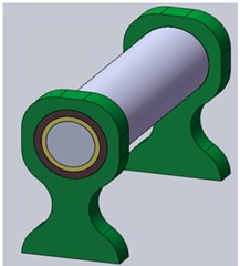
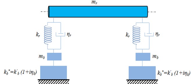
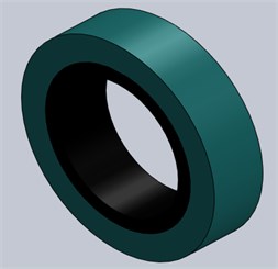
The bearings used in rotating machines (turbines, centrifugal pumps) generally comprise bearings whose main function is to ensure proper operating and to better control the vibration of the bearing Fig. 1, as well as the physical model supported by two bearings is represented by Fig. 2.
Fig. 1Hydrostatic bearing with magnetorheological elastomer shell bearing
a)

b)

c)
Fig. 2Physical model supported by two bearings with magnetorheological elastomer shell bearing
3. Mathematical modeling of vibrations
3.1. Modeling of the rotor behavior
The shaft is modeled by a rotating Timoshenko beam. The general formulation of the kinetic [27] and the deformation energies of the shaft integrating these formulas on the length of the shaft, it comes:
The deformation energy of a rotating Timoshenko beam [17] is equal to:
where is the correction factor for shear stiffness.
3.2. Modeling the behavior of the shell bearing
The damped vibratory movement of the MRE shell bearing is modeled by the system given in Fig. 3.
Fig. 3The MRE shell bearing model
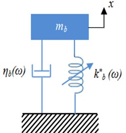
The equation of movement of the MRE shell bearing of Fig. 3 is given from the second law of motion, , in which is equivalent to the sum of the restoring force and the damping force . In this last expression, represents a positive damping which is adjustable by the application of a magnetic field. So, we get:
The solution of this differential equation corresponds to:
In the case of a magnetorheological elastomer, the complex rigidity is given by:
then:
It is also possible to define a complex viscosity as follows:
with:
where and are associated with the loss modulus and the conservation modulus respectively.
3.3. Modeling of the magnetorheological elastomer
For small displacements and relatively small times t, the response of a viscoelastic material is dominantly elastic for constant strain rates, and that for larger values of , the response is dominantly or entirely viscous.
The Maxwell model can accurately describe creep behavior in magnetorheological elastomer with small displacements. This model represents a viscoelastic material with several parallel branches such as a spring and a dashpot in parallel and is particularly accurate in predicting creep behavior.
Prony series parameters , , and were needed to characterize the creep displacement behavior in Abaqus. Shear and bulk moduli were then calculated using these parameters (Keenan) in order to compute the analytical solution:
4. Elaboration and experimental analysis of MRE
4.1. Steps elaboration and mechanical characterization
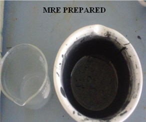
The rheological parameters of the MRE shell bearing as a function of the magnetic field are determined experimentally using the MetraviB DMA + 450 viscoanalyser Fig. 4(b) (PMC Laboratory, Nice, France). The elastomer is prepared (Fig. 4(a)) by the following steps:
Mixing the silicone oil and the RTV141A polymer in a bowl and proceed with a manual mixing during 10 min to obtain an elastomer gel with good homogenization. A second bowl containing a quantity of iron particles of micrometric size to loading the elastomer is prepared.
Fig. 4a) Prepared elastomer, b) MetraviB DMA + 450 Viscoanalyser
a)
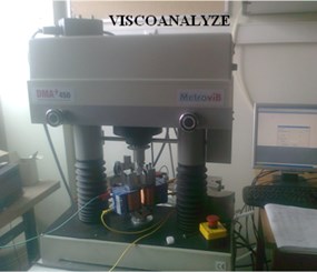
b)
A quantity of this gel obtained by silicone and RTV141A is mixed during 30 min with a quantity of iron particles until obtaining a homogeneous paw. By this process, an elastomer loaded with 30 % of ferromagnetic particles is elaborated.
The degassing of the obtained paw under vacuum during 10 min to eliminate air bubbles in filtrated during the mixing is performed in order to have a healthy structure for the experimentation. The obtained elastomer is hermetically pre- served at low temperature.
The specimen has a rectangular shape of 30 mm of length, 28 mm of width, and 2 mm of thickness and loaded with 40 % of ferromagnetic particles of its total volume. The values of the storage and loss modulus obtained with and without the magnetic field are given in Table 1 [28].
Table 1Experimental data of shear moduli G' and G''
0 A | 0.5 A | 1.2 A | 2 A | ||||
(MPa) | (MPa) | (MPa) | (MPa) | (MPa) | (MPa) | (MPa) | (MPa) |
1.8328 | 0.3236 | 2.1461 | 0.7036 | 3.1527 | 1.0334 | 2.9660 | 0.7248 |
1.2847 | 0.3148 | 1.5403 | 0.5410 | 2.1824 | 0.7340 | 2.5806 | 0.6335 |
1.01643 | 0.2495 | 1.2133 | 0.4019 | 1.6262 | 0.5323 | 2.3134 | 0.5763 |
0.8186 | 0.2200 | 0.8716 | 0.2979 | 1.1262 | 0.3482 | 1.7035 | 0.4636 |
0.6805 | 0.1895 | 0.7658 | 0.2770 | 0.8908 | 0.2947 | 1.3160 | 0.3595 |
0.6197 | 0.1521 | 0.7143 | 0.2317 | 0.7546 | 0.3206 | 1.1240 | 0.3136 |
5. Numerical simulation of shell bearing
To deal with the problem of reducing the amplitude of vibrations by the MRE shell bearing and the housing, we used a multi-body equivalent model in the Abaqus software (Fig. 5(a), (b)). The results of the meshing give 2476 elements for the shell bearing and 4805 for the housing.
Fig. 5Finite elements model of a bearing: a) without mesh, b) with mesh
a)
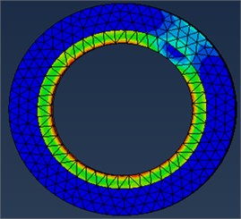
b)
The geometric and mechanical parameters of the studied bearing are given in Table 2.
Table 2Geometric and mechanical parameters of the bearing
Housing radius | 25 mm |
Width of the housing | 25 mm |
Thickness of the shell bearing | 2 mm |
Elasticity modulus of the housing | 199000 MPa |
Poisson’s ratio of the housing | 0.29 |
Density of the housing | 7800 kg/m3 |
Poisson’s ratio of the shell bearing | 0.45 |
Density of the shell bearing | 1100 kg/m3 |
Fluid supply pressure | 0.1 MPa |
5.1. Results and discussions
An implicit model using the Abaqus software is taken up using the six-branch Maxwell generalized rheological model and the Prony series to analyze the influence of the MRE shell bearing on the rotor vibratory behavior. After recalling the main mechanical and rheological characteristics of the different parts, a complete modeling of the bearing and housing by the finite element method using the Abaqus software which allow meshing each of the two parts by C3D10 parabolic tetrahedron elements to ensure the convergence Fig. 5. Nevertheless, the representation of the viscoelastic core by volume elements is intended to take into account the shear responsible for damping in this layer. The numerical results found of the various parameters as a function of the intensity of the magnetic field are given by the Table 3.
Table 3The numerical results found of the different parameters according to the intensity of the current
0 A | 0.5 A | 1.2 A | 2 A | ||||||||
(mm) | (Hz) | (mm) | (Hz) | (mm) | (Hz) | (mm) | (Hz) | ||||
1.304 | 0.18 | 396.24 | 1.300 | 0.33 | 587.48 | 1.293 | 0.33 | 717.60 | 1.289 | 0.24 | 604.94 |
1.001 | 0.24 | 397.69 | 1.001 | 0.35 | 589.62 | 1.001 | 0.34 | 720.16 | 1.001 | 0.24 | 607.01 |
1.267 | 0.25 | 404.22 | 1.282 | 0.33 | 617.06 | 1.277 | 0.33 | 732.06 | 1.271 | 0.25 | 599.34 |
1.004 | 0.27 | 406.22 | 1.005 | 0.34 | 620.73 | 1.004 | 0.31 | 736.14 | 1.004 | 0.27 | 602.46 |
1.352 | 0.24 | 413.49 | 1.363 | 0.32 | 632.39 | 1.351 | 0.33 | 749.75 | 1.348 | 0.27 | 613.38 |
The displacement response corresponding to the first five vibration modes of the MRE shell bearing at 27°C and under a harmonic stress is shown in Fig. 6 as a function of different values of the current intensity. It is found that the amplitude is maximum and reaches critical values in the modes 1, 3 and 5. A low amplitude for modes 2 and 4. This observation is clearly shown in Fig. 7; the amplitude reaches critical values for odd modes and low amplitudes for even modes.
Fig. 6Variation of the amplitude as a function of the current intensity
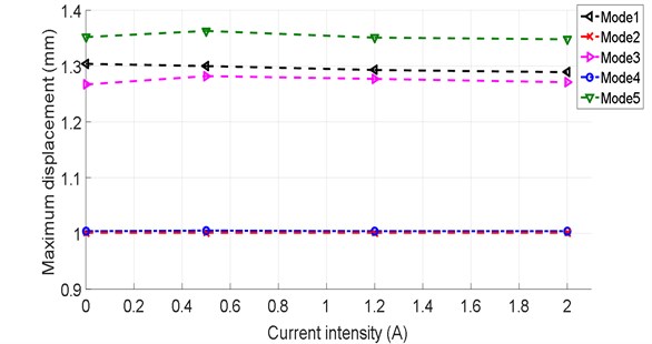
Fig. 7 shows the evolution of maximum displacement of the shell bearing modeling using Abaqus, as a function of natural frequencies. We found surprisingly that the natural frequency increases with the increase of the current intensity. There is also a significant increase in the frequency between a zero current intensity and for current intensities ranging between 0.5 and 2 A which gives an increase of the order of 53 %. This is due to the effect of the electric field on the rigidity of the system.
This figure shows that the displacements of the rotor are reduced as a function of the increase of the magnetic field and this is due to the increase of the rigidity of the MRE shell bearing. As the frequency increases with the increase of the intensity of the magnetic field (that is to say as a function of the increase of the rigidity of the MRE shell bearing).
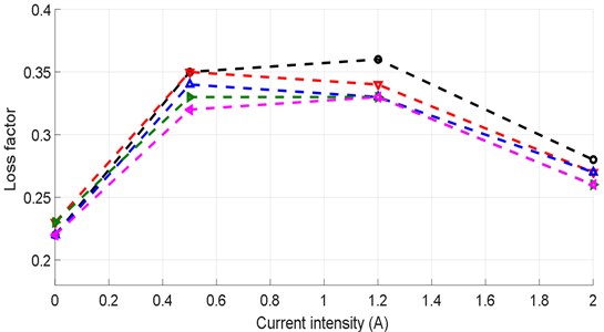
The results in Table 3 show us that the damping of the MRE shell bearing increases with the electric field. The variation of the damping rate is shown in Fig. 8, it can be seen that the damping rate of the shell bearing increases rapidly with the electric field for low values of current intensity, practically of up to 0.5 A, and then we notice a stabilization phase for intensity values varying from 0.5 to 1.2 A, and then gradually decreasing. This is due to the increase of the attractive force between the ferromagnetic particles due to the increase of the electric field. The damping rate increases by 45 % for the first phase (0 ≤ ≤ 0.5) A, which represents a significant increase. We can see an asymptotic increase in the damping rate for the second phase, which shows its limit.
Fig. 7Modes and frequencies of vibration according to the current intensity
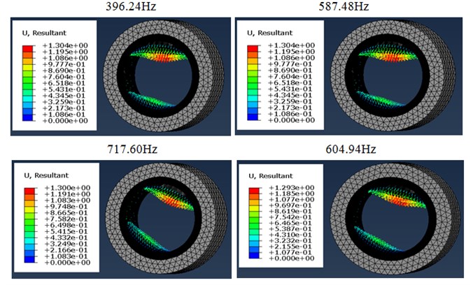
a) 1st mode
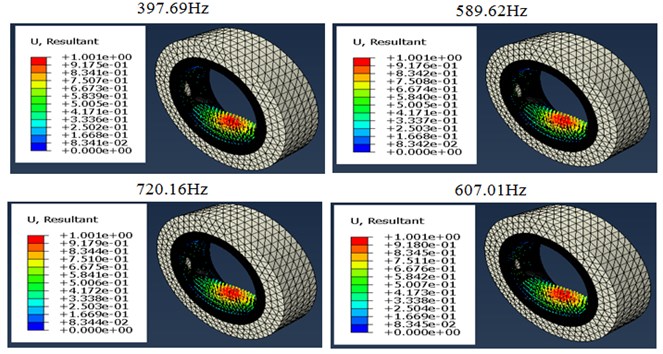
b) 2nd mode
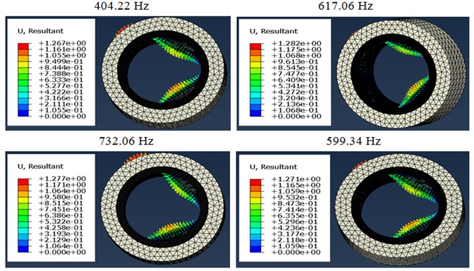
c) 3rd mode
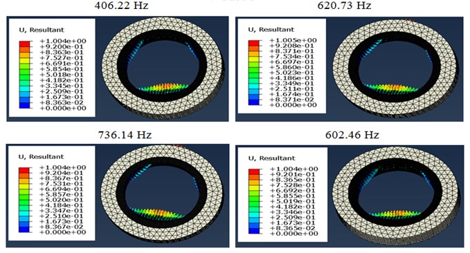
d) 4th mode
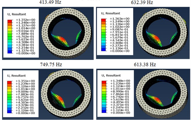
e) 5th mode
Fig. 8Variation of the damping rate according to the current intensity
The results of the identification of the mechanical behavior (Table 4) of the shell bearing as a function of the magnetic field intensity are presented in Fig. 9. It appears that the increase in the magnetic field intensity makes it possible to appreciably increase the stress and the deformation. We have found that in the presence of a magnetic field, the attractive force between the iron particles increases which gives a greater sliding movement, these two phenomena are the basis of increase of the stress and the deformation simultaneously.
Table 4Variation of the stresses vs. strain under different magnetic field intensities
0 T | 0.15 T | 0.3 T | 0.45 T | ||||
(MPa) | (MPa) | (MPa) | (MPa) | ||||
2.822×10⁻⁵ | 2.957×10⁻³ | 2.131×10⁻⁵ | 3.022×10⁻³ | 1.990×10⁻⁵ | 3.053×10⁻³ | 1.929×10⁻⁵ | 3.084×10⁻³ |
6.373×10⁻⁵ | 3.326×10⁻³ | 4.460×10⁻⁵ | 3.399×10⁻³ | 4.027×10⁻⁵ | 3.435×10⁻³ | 3.783×10⁻⁵ | 3.470×10⁻³ |
9.925×10⁻⁵ | 3.696×10⁻³ | 6.789×10⁻⁵ | 3.777×10⁻³ | 6.063×10⁻⁵ | 3.816×10⁻³ | 5.637×10⁻⁵ | 3.855×10⁻³ |
1.348×10⁻⁴ | 4.066×10⁻³ | 9.188×10⁻⁵ | 4.155×10⁻³ | 8.100×10⁻⁵ | 4.198×10⁻³ | 7.491×10⁻⁵ | 4.241×10⁻³ |
1.703×10⁻⁴ | 4.435×10⁻³ | 1.145×10⁻⁴ | 4.532×10⁻³ | 1.014×10⁻⁴ | 4.580×10⁻³ | 9.345×10⁻⁵ | 4.626×10⁻³ |
Fig. 9Variation of the stress developed within the shell bearing according to the strain
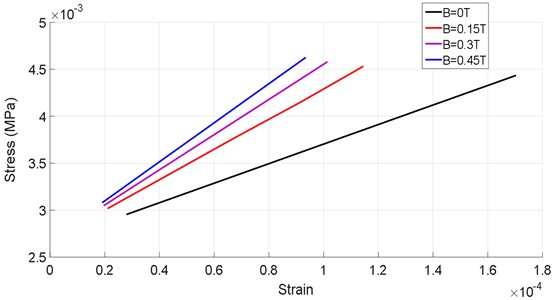
Table 5Variation of the displacements vs to the strain under different the intensity of the magnetic field
0 T | 0.15 T | 0.3 T | 0.45 T | ||||
(mm) | (MPa) | (mm) | (MPa) | (mm) | (MPa) | (mm) | (MPa) |
3.540×10⁻⁴ | 4.435×10⁻³ | 2.363×10⁻⁴ | 4.532×10⁻³ | 2.086×10⁻⁴ | 4.580×10⁻³ | 1.917×10⁻⁴ | 4.626×10⁻³ |
6.606×10⁻⁴ | 4.066×10⁻³ | 4.424×10⁻⁴ | 4.155×10⁻³ | 3.911×10⁻⁴ | 4.198×10⁻³ | 3.599×10⁻⁴ | 4.241×10⁻³ |
9.672×10⁻⁴ | 3.696×10⁻³ | 6.485×10⁻⁴ | 3.777×10⁻³ | 5.735×10⁻⁴ | 3.816×10⁻³ | 5.281×10⁻⁴ | 3.855×10⁻³ |
1.274×10⁻³ | 3.326×10⁻³ | 8.546×10⁻⁴ | 3.399×10⁻³ | 7.560×10⁻⁴ | 3.435×10⁻³ | 6.963×10⁻⁴ | 3.470×10⁻³ |
1.580×10⁻³ | 2.975×10⁻³ | 1.061×10⁻³ | 3.022×10⁻³ | 9.385×10⁻⁴ | 3.053×10⁻³ | 8.645×10⁻⁴ | 3.084×10⁻³ |
Fig. 10Variation of the stress developed within the shell bearing according to the displacement of the rotor
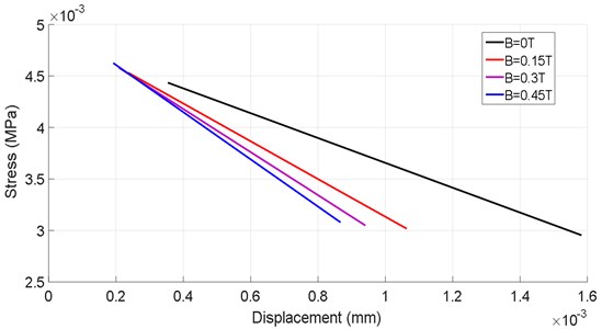
The variation of the stress developed within the shell bearing as a function of the displacement (Table 5) of the rotor is shown in Fig. 10. There is a considerable decrease in rotor displacements with the increase of the magnetic field intensity, in the case of 0 T, one has a displacement increasing from (0.38 to 1.5) .10-3 unit on the other hand in the case of 0.45 T one has a displacement increasing from (0.18 to 0.83). 10-3 unit, thus with a rate of reduction great than 50 %.
6. Conclusions
In this work, a new hydrostatic bearing with magnetorheological elastomer shell bearing has been designed to control the undesirable vibrations of rigid rotors.
This system of active vibration control of rigid rotors using magnetorheological elastomer bearings has aroused great interest for engineers and researchers because it combines the advantages of active-passive control, and it does not need great external energy, it responded even with low electrical intensity.
The Maxwell model is used to better describe the rheological behavior of the magnetorheological elastomer using the Abaqus software. This model is based on experimental data. This model of MRE damper has been applied to a simplified system with one degree of freedom with complex rigidity. However, this model allowed us to realize numerically a system of active control of rotor vibrations. The results of the numerical simulation can be summarized as follows:
The magnetorheological elastomer shell bearing of a hydrostatic bearing was used as an effective control system to limit the vibration amplitude on the one hand and to reduce the transmitted force on the other hand. The application of the electric field has a significant influence on the damping rate at low current intensity, whereas the increase in intensity has no effect on the damping rate. The increase in the intensity of the electric field increases the rigidity, and therefore, the damping rate decreases beyond the stabilization intensity and this is due to the reduction of the dissipative modulus. To reduce the amplitude of the vibratory response of the excited rotor by an imbalance, it is sufficient to use an MRE shell bearing with a low intensity to obtain a high damping. Otherwise, the use of high electric field intensity is not necessary. On the other hand, the use of an MRE shell bearing with high electric field intensity is very effective in reducing the force transmitted to the base. When the rotor is operating near the critical speed, the electric field must not be high in order to obtain high damping.
References
-
Frêne J., Nicolas D. Lubrification Hydrodynamique, Paliers Et Butées. Eyrolles, Editeur Paris, 1990.
-
Sun Y., Thomas M., Masounave J. Damping of rotor torsional vibrations with electrorheological fluids. Proceedings of the 24th Seminar on Machinery Vibration, Canadian Machinery Vibration Association, 2006, p. 344-369.
-
Nikolajsen J. L., Roque M. S. An electroviscous damper for rotor applications. Journal of Vibration, Acoustics, Stress, and Reliability in Design, Vol. 112, 1990, p. 440-443.
-
Morishita S., Mitsui J. Controllable squeeze film damper (An application of electro-rheological fluid). Journal of Vibration and Acoustics, Vol. 114, Issue 3, 1992, p. 354-357.
-
Tichy J. A. Behavior of a squeeze film damper with an electrorheological fluid. Tribology Transactions, Vol. 36, 1993, p. 127-133.
-
Lee N. S., Choi D. H., Seok K. Y., Lee Y. B., Kim C. H. Vibration control of a flexible rotor with a slotted-rin a sealed electro-rheological squeeze film damper. Proceedings of IMECH 7 International Conference, 2000, p. 499-508.
-
Seungchul L., Sang-Min P., Kab-II K. AI vibration control of high-speed rotor systems using electrorheological fluid. Journal of Sound and Vibration, Vol. 284, 2005, p. 685-703.
-
Guozhi Y., Fah Y. F., Guang C., Guang M., Tong F., Yang Q. Electro-rheological multi-layer squeeze film damper and its application to vibration control of rotor. Journal of Vibration and Acoustics, Vol. 22, 2000, p. 7-11.
-
Pecheux B., Bonneau O., Frêne J. Investigation about electro-rheological squeeze film damper applied to active control of rotor dynamic. International Journal of Rotating Machinery, Vol. 3, Issue 1, 1997, p. 53-60.
-
Bouzidane A., Thomas M. Equivalent stiffness and damping investigation of a hydrostatic journal bearing. Journal Tribology Transactions, Vol. 50, Issue 2, 2007, p. 257-267.
-
Bouzidane A., Thomas M. An electrorheological hydrostatic journal bearing for controlling rotor vibration. Computers and Structures, Vol. 86, Issues 3-5, 2008, p. 463-472.
-
Bouzidane A., Thomas M., Lakis A. A nonlinear dynamic behavior of a rigid rotor supported by hydrostatic squeeze film dampers. Journal of Tribology, Vol. 130, Issue 4, 2008, p. 717-727.
-
Sharana J., Basavaraja S., Sharma C., Satish C. A study of misaligned electrorheological fluid lubricated hole-entry hybrid journal bearing. Tribology International, Vol. 43, Issues 5-6, 2010, p. 1059-1064.
-
Dimitrios A., Bompos P., Nikolakopoulos G. CFD simulation of magnetorheological fluid journal bearings. Simulation Modelling Practice and Theory, Vol. 19, Issue 4, 2011, p. 1035-1060.
-
Xiaohu W., Hongguang L., Guang M. Rotor dynamic coefficients of a controllable magnetorheological fluid lubricated floating ring bearing. Tribology International, Vol. 114, 2017, p. 1-14.
-
Zhongliang Xi, Zhushi R., Na T. Investigation on the lubrication regimes and dynamic characteristics of hydro-hybrid bearing of two-circuit main loop liquid sodium pump system. Annals of Nuclear Energy, Vol. 115, 2018, p. 220-232.
-
Sandeep S., Rajiv T. Model based identification of crack and bearing dynamic parameters in flexible rotor systems supported with an auxiliary active magnetic bearing. Mechanism and Machine Theory, Vol. 122, 2018, p. 292-307.
-
Naoki H., Masanori K., Masaaki M., Shigeka Y. Static characteristics of a water-lubricated hydrostatic thrust bearing with a porous land region and a capillary restrictor. Precision Engineering, Vol. 50, 2017, p. 293-307.
-
Yu H., Zhuxin T. A new derivation to study the steady performance of hydrostatic thrust bearing: Rabinowitch fluid model. Journal of Non-Newtonian Fluid Mechanics, Vol. 246, 2017, p. 31-35.
-
Seperamaniam T., Nawal A., Abdul J., Zamir A. Z. Hydrostatic bearing design selection for automotive application using Pugh controlled convergence method. Procedia Engineering, Vol. 170, 2017, p. 422-429.
-
Enle X., Yue W., Jianeng W., Shichang X., Yuxin W., Shichang W. Investigations on the applicability of hydrostatic bearing technology in a rotary energy recovery device through CFD simulation and validating experiment. Desalination, Vol. 383, 2016, p. 60-67.
-
Makoto G., Kei S., Masaaki M., Shigeka Y. Static characteristics of a water-lubricated hydrostatic thrust bearing using a membrane restrictor. Tribology International, Vol. 75, 2014, p. 111-116.
-
Udaya P. S., Ram S. G., Vijay K. On the application of Rabinowitsch fluid model on an annular ring hydrostatic thrust bearing. Tribology International, Vol. 58, 2013, p. 65-70.
-
Lu L., Su H., Liang Y., Zhang Q. Research on static stiffness of hydrostatic bearing using fluid-structure interaction analysis. Procedia Engineering, Vol. 29, 2012, p. 1304-1308.
-
Satish C. S., Vikas M. P. S., Jain C. Performance analysis of a multi recess capillary compensated conical hydrostatic journal bearing. Tribology International, Vol. 44, 2011, p. 617-626.
-
Manish K., Daejong K. Static performance of hydrostatic air bumpfoil bearing. Tribology International, Vol. 43, 2010, p. 752-758.
-
Lalanne M., Ferraris G. Rotor Dynamics Prediction in Engineering. 2nd Ed., John Wiley, Chichester, New York, 1998.
-
Chikh N., Nour A., Aguib S., Tawfiq I. Dynamic analysis of the non-linear behavior of a composite sandwich beam with a magnetorheological elastomer core. Acta Mechanica Solida Sinica, Vol. 29, Issue 3, 2016, p. 271-283.
About this article

Thanks to Laboratory of Condensed Matter Physics (LPMC) University of Nice – Sophia Antipolis – France, for providing various supports for this study. We are also grateful to Messrs George Bossis Research Director Emeritus and Dr. Kuzhir Pavel of LPMC, for their help.
Chikh Noureddine leaded all team works and participated in the entire process, guided derivation of the optimal finite element method. Aguib Salah contributed fully to the numerical simulation as well as to the theoretical formulation of equations governing the hydrostatic behavior of the smart bearing. Djedid Toufik checked the theoretical formulation of the equations governing the behavior of the hydrostatic smart bearing and the verification of the English language. Nour Abdelkader reviewed and contributed to this article with important proposals in both theoretical study and numerical study. Tawfiq Imad reviewed and participated in the general design of the revised paper and the verification of the English language.
