Abstract
Unilateral external fixators are widely used in orthopedics to stabilize fractured bones and in the treatment of limb deformities. Vivo mechanical environment inside and around the fixator may influence the healing of fractured bone. Due to the existence of pin deviation may affect biomechanical environment of callus in the fracture gap. Finite element analysis was used to investigating stress and deformation of fixator-bone system under axial load, torsional load and bending load, comparing the biomechanical properties of two fixator structures: the one has pin deviation angle, the other has no pin deviation angle. These results reveal that the existence of pin deviation would affect the biomechanical environment of fractured bone. When fixator-bone system under three kinds of load, the stress and deformation of fixator-bone system were greater than that of fixator-bone system without pin deviation. This work provides orthopedics doctor useful information to predict the micromovements of fixator-bone system.
1. Introduction
External fixation offers various advantages compared with other fixation methods [1-3]. In the majority of cases, it allows for easy reduction of the fracture, even under unfavorable soft-tissue conditions; in addition, secondary corrections can be made [4]. Furthermore, it is possible to modify fixation stiffness during treatment. Despite these positive qualities, there is a persistent high incidence of complications due to the progressive mechanical deterioration of the bone-pin interface, which leads to pin loosening and infection [5-8]. The stability of external fixator system has an important impact on the stresses and strains at the pin-bone interface. The pins are fundamental for the external fixation system. Pins in an external fixator are required to transmit large changing loads across the pin-bone interface and stabilizing this interface to prevent micromotion is a difficult problem. Stress created by an external fixator very likely has its pin loosening effect at the pin-bone interface. Unstable fracture fixation allows pin bending moments that cause fluctuating compressive stresses on the pin tract. Successful external fixator requires the stability of the apparatus and integrity of the pin-bone interface. Clinically, half-pins are inserted through the soft tissue to the bone from one side of the limb. Under ideal situations, pins are inserted into the bone perpendicularly, and the fixator is applied in neutral or straight position [9]. However, in the actual situation, it is difficult to inserting the pins into the bone accurately and appropriately as ideal situation. Pin deviation may affect bone stability and mechanical environment of the fixator-bone system and tissue in the fracture gap. Besides, callus formation is directly influenced by inter-fragmentary movement: less callus formation has been observed under stable conditions with small inter-fragmentary movements [10]. While delayed union or non-union was observed in cases of excessive inter-fragmentary movements [11-13]. So, the existence of pin deviation may influence micro-movements of fixator-bone system, and then affect the fracture healing process. Meanwhile, how pin deviation influences the pin loosening and the biomechanical properties of the fixator-bone system, has never been clear and rarely studied by previous researchers.
Therefore, the main goal of this study was to adapt finite element method to investigate the influence of pin deviation on the biomechanical environment of fixator-bone system under axial, torsional and bending load, through two different fixator-bone structures: the one is that pins are inserted into the bone perpendicularly without pin deviation, the other is that proximal pins are inserted into the bone with angular deviation. Through this study, the influence of pin deviation on the displacement, stress of the fixator-bone system can be obtained. Besides, this study provides useful information for orthopedics doctor to predict the stability of fixator-bone system.
2. Methods
2.1. Three-dimensional model of fixator-bone system
CT images were used to establish the model of lower limb in this study. The slice thickness of the CT images was 1.5 mm in a 512×512 matrix. The DICOM data set, which consists of 225 CT images, was imported into Mimics (software version 18.0, Materialise, Leuven, Belgium) to reconstruct the surface geometry of the tibia. Based on the bone density threshold value, a segmentation process was carried out each slice of the CT data to generate tibia bone.
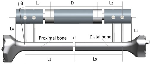
The external fixator systems, the Orthofix frames were designed using three-dimensional Computer Aided Design software (Solidworks 2012, Dassault Systems Solidworks Corp.USA). To simulate bone fixation, two pins were fixed at the tibial diaphysis, the distance between the external and the bone was set at 45 mm. The two-different pin-fixator structures shown in Fig. 1, the one is that pins are inserted into the bone perpendicularly without pin deviation, the other is that distal pins are inserted into the bone with 15 degrees of angle and proximal pins have no pin deviations. The distance between the external and the bone was set at 40 mm for two structures.
Fig. 1The physical model of fixator-bone system. L0=L5= 83 mm; L2=L3= 40 mm; D= 90 mm; d= 4 mm, L4= 60 mm, θ= 0-30°
2.2. Finite element model of fixator-bone system
The STL files of the bones was imported into ANSYS (ANSYS.Software, US) and meshed with tetrahedral elements. Using a finite element model created with 10 node tetrahedral elements, for a total of 57,674 elements and 90,500 nodes. The convergence of the finite element results was confirmed by increasing mesh density. The (isotropic) Young’s modulus of cortical bone was taken equal to the average value of the Young’s modulus of the BONE models. The cortical bone has been considered with elasticity modulus 17 GPa and a Poisson’s ratio of 0.3 [14]. The specific mass of bone is considered with1800 kg/m3.
The fixators were meshed with four nodes tetrahedral linear elements. The total number of elements and nodes for the fixator model are 624,000,139,000 in fixator-bone system. The contact surface between the external fixator and the bone was set with a friction coefficient of 0.4 based on a previous study [15]. The fixator was assigned a Young’s modulus of 190 GPa and a Poisson’s ratio of 0.3 (manufacturer’s data). These values were also applied to the fixator parts. For the unilateral fixator, the stainless steel parts, being the extension tubes, screws, bolts and fixator rod, were assigned a Young’s modulus of 190 GPa and a Poisson’s ratio of 0.3. The contact settings between the various fixator parts were adopted from a previous study [16].
2.3. Loading and boundary conditions
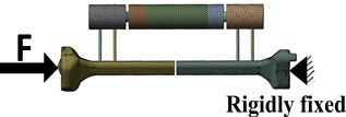
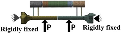
Loading and boundary conditions can be shown in Fig. 2. When applied axial load, boundary conditions for the fixator-system are shown in Fig. 2(a). the distal bone end was fixed, and proximal bone end was subjected to a axial force (600 N). When fixator-bone system under torsional load, the distal bone end was fixed and proximal bone end was subjected to a torque (15 N.m/degree) shown in Fig. 2(b). For 4-point bending load, the two loads were applied on the position 90 mm away from the fracture gap (500 N) shown in Fig. 2(c). The degrees of freedom (DOFs) of the bone ends were fixed. For these three loading conditions, to avoid apparent stress concentration, the loads were applied onto the eight nodes surrounding the loading points. Fixator-bone system with pin deviations or without pin deviations are applied same loads and conditions.
Fig. 2Loading and boundary condition for fixator-bone system with pin deviations or without pin deviations: a) loading and boundary conditions for compression load, b) loading and boundary conditions for torsion load, c) loading and boundary conditions for 4-point bending
a)

b)
c)
3. Results
3.1. Stress of fixator-bone system without pin deviation under three loads
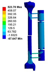
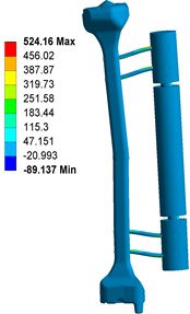
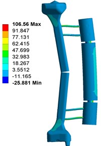
Fig. 3 shows the contour plots of the equivalent von Mises stress for the fixator-bone system without pin deviations under axial torsional and bending loads. Shown in Fig. 3(a), when fixator-bone system is in neutral position and having no pin deviations, the maximum stress value was 523.78 MPa occurred at the contact surface between pin and bone. When under torsional load, the maximum stress value (524.16 MPa) also observed at the pin surface, and approximately equivalent to that of the axial load, as shown in Fig. 3(b). In addition, greater torsional load can lead to stress shielding at fracture site. Nevertheless, for Fig. 3(c), the highest von Mises stress occurred at the bone closed to the pin, which is 106.56 MPa, that is far lower than that of axial and torsional loads.
3.2. Deformation of fixator-bone system without pin deviation under three loads
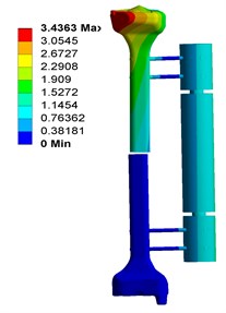
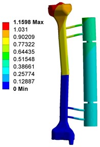
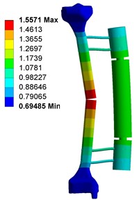
Fig. 4 shows the deformation of fixator-bone system without pin deviation, when under axial, torsional and bending load. Fig. 4(a) shows that, under axial load, the maximum deformation of fixator-bone system is 3.4363 mm and occurs on the pin-bone surface. For Fig. 4(b), the maximum torsional deformation is 1.1598 mm, and appear on the fractured site. Fig. 4(c) displays the deformation of fixator-bone system when applied bending load, the results also predicted that bending load cause a deformation (1.5771 mm) at the fractured site.
Fig. 3Stress distribution of fixator-bone system without pin deviation under axial, torsional and bending load: a) stress distribution of fixator-bone system without pin deviations under axial load, b) stress distribution of fixator-bone system without pin deviations under torsional load, c) stress distribution of fixator-bone system without pin deviations under bending load
a)
b)
c)
Fig. 4Deformation of fixator-bone system without pin deviation under axial, torsional and bending load: a) deformation of fixator-bone system without pin deviation under axial load, b) deformation of fixator-bone system without pin deviation under torsional load, c) deformation of fixator-bone system without pin deviation under bending load
a)
b)
c)
3.3. Influence of angular deviation on the fixator-bone system under three loads
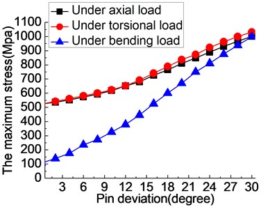
Shown in Fig. 5(a), when fixator-bone system under axial load and pin deviation changed 0-20 degrees, the stress growth trend showed a slow increasing trend and reached to 680 MPa, compared with having no pin deviation, increased by about thirty percent. After the pin deviation of 20 degrees, the trend of stress begins to steeper, meaning the effect of pin deviation on the fixator-bone system will greater. The same information can also be observed on the torsional load, when pin deviation increases from 0-20 degrees, the growth trend of stress is relatively slow, while the growth trend of stress begins to higher when the pin deviation angle is bigger than 20 degrees. The results indicate that the presence of pin deviation angle make the maximum stress of fixator-bone system increased, which will conductive to harm the healing process of bone. When fixator-bone system under bending load, similar phenomenon can also be observed. The change of pin deviation has the greatest influence on the biomechanical environment of fixator-bone system. Because, pin deviation changes 1 degree, the maximum stress of fixator-bone system average increased by 19.82 MPa under bending load, increased by 10.707 MPa under axial load, and increased by 10.894 MPa under torsional load.
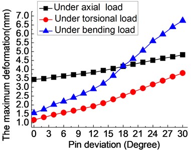
Fig. 5(b) displays the influence of pin deviation (0-30°) on the deformation of fixator-bone system under axial, torsional and bending loads. No matter what kind of load, the presence of pin deviation could increase the deformation of the fixator-bone system. Similar to the stress results, when pin deviation varies from 0° to 20°, the deformation of fixator-bone system shows a slowly increased trend under three loads. Meanwhile, the growth rate of deformation becomes bigger when deviation angle is more than 20 degrees. The same rule doesn't look obviously in axial load, due to the growth rate of the maximum deformation is very small, indicating the effect of pin deviation on the axial stiffness and stability of the fixator-bone system is relatively small, but still have great influence on the biomechanical environment fixator-bone system.
Fig. 5The influence of pin deviation (0-30°) on the fixator-bone system under axial, torsional and bending load: a) the influence of angular deviation (0-30°) on the stress of fixator-bone system under axial, torsional and bending load, b) the influence of angular deviation (0-30°) on the deformation of fixator-bone system under axial, torsional and bending load
a)
b)
4. Conclusions
In our study, no matter applied what kind of load, the present of pin angle deviation could cause the stress and displacement of fixator-bone system increased, which could harm to the stability of fixator-bone system. More important, when pin deviation angle changes during 0-20°, the growth rate of stress or deformation very slow, and when it’s more than 20°, the trend began to steeper, meaning the effect of pin deviation on the stability of the fixator-bone system will greater. Therefore, the orthopedics should try to avoid the pin deviation angle greater than 20 degrees in the process of operation. Besides, compared with the axial and torsional load, a change in deviation angle has a greater influence on the stress or deformation value of fixator-bone system due to higher rise rate, when under bending load.
References
-
Huiskes R., Chao E. Y. S., Crippen T. E. Parametric analyses of pin-bone stresses in external fracture fixation devices. Journal of Orthopaedic Research, Vol. 3, Issue 3, 1985, p. 341-349.
-
Manley M. T., Hurst L., Hindes R., et al. Effects of low-modulus coatings on pin-bone contact stresses in external fixation. Journal of Orthopaedic Research, Vol. 2, Issue 4, 1984, p. 385-392.
-
Chao E. Y. S., Hein T. J. Mechanical performance of standard Orthofix external fixator. Orthopedics, Vol. 11, Issue 7, 1988, p. 1057-1069.
-
Jaskulka R. A., Egkher E., Wielke B. Comparison of mechanical performance of three types of unilateral, dynamizable external fixators. Archives of Orthopaedic and Trauma Surgery, Vol. 113, Issue 5, 1994, p. 271-275.
-
Caja V., Kim W., Larsson S. Comparison of the mechanical performance of three types of external fixators: linear, circular and hybrid. Clinical Biomechanics, Vol. 10, Issue 8, 1995, p. 401-406.
-
Behrens F. General theory and principles of external fixation. Clinical Orthopaedics and Related Research, Vol. 241, Issue 241, 1989, p. 15-23.
-
Aro H. T., Markel M. D., Chao E. Y. S. Cortical bone reactions at the interface of external fixation half-pins under different loading conditions. The Journal of Trauma, Vol. 35, Issue 5, 1993, p. 776-855.
-
Chao E. Y. S., Aro H. T. Biomechanics of fracture repair and fracture fixation. Basic Orthopaedic Biomechanics, Vol. 7, Issue 9, 1991, p. 293-336.
-
Yamaji T., Ando K., Wolf S., Augat P., Claes L. The effect of micromovement on callus formation. Journal of Orthopaedics Science, Vol. 6, Issue 6, 2001, p. 571-575.
-
Liu R. W., et al. Computational simulation of axial dynamization on long bone fractures. Clinical Biomechanics, Vol. 20, Issue 1, 2005, p. 83-90.
-
Carter D. R., Blenman P. R., Beaupre G. S. Correlations between mechanical stress history and tissue differentiation in initial fracture healing. Journal of Orthopaedic Research, Vol. 6, Issue 5, 1988, p. 736-748.
-
Kenwright J., Goodship A. E. Controlled mechanical stimulation in the treatment of tibial fractures. Journal of Orthopaedic Research, Vol. 241, Issue 241, 1989, p. 36-47.
-
Chao E. Y., Inoue N. Biophysical stimulation of bone fracture repair, regeneration and remodelling. European Cells and Materials, Vol. 31, Issue 6, 2003, p. 72-84.
-
Orr T. E., Villars P. A., Mitchell S. L., Hsu H. P., Spector M. Compressive properties of cancellous bone defects in a rabbit model treated with particles of natural bone mineral and synthetic hydroxyapatite. Biomaterials, Vol. 22, Issue 14, 2001, p. 1953-1959.
-
Karunratanakul K., Schrooten J., Van Oosterwyck H. Finite element modelling of a unilateral fixator for bone reconstruction: importance of contact settings. Journal of Biomechanics, Vol. 41, Issue 5, 2008, p. 249-265.
-
Claes L. E., Heigele C. A. Magnitudes of local stress and strain along bony surfaces predict the course and type of fracture healing. Journal of Biomechanics, Vol. 32, Issue 3, 1999, p. 255-266.
About this article

