Abstract
This paper provides a program to adopt based on modeling the nonlinear behavior of arbitrary elements with combination of material nonlinearity and geometric nonlinearity for the purpose of structures assessment. In this study, total Lagrangian formulation is developed based on separate fibers with uniaxial behavior and interface elements with shear response of local stress field models, simultaneously. The accuracy of the suggested approach is verified through comparison of experimental results and existing analytical methods.
1. Introduction
Numerous efforts are done to improve upon the accuracy of conventional displacement-based beam-column finite elements for geometric and material nonlinear analysis of frame structures by many researchers. Crivelli and Felippa [1] and Eduardo et al. [2] developed an incremental Total Lagrangian formulation for beam elements that included the effect of large rotation and the effect shear influence. Zhang et al. [3] presented the small strain beam element stiffness by combining Timoshenko beam theory with fiber model in deep beams. Also, Kabeyasawa et al. [4] proposed a macro model called Three Vertical Line Element Model (TVLEM) for numerical modeling of reinforced concrete shear walls and subsequent development of TVLEM was Multiple-Vertical-Line Element Model (MVLEM) presented by Vulcano et al. [5]. Numerical simulations investigating fiber approaches have been carried out by several researchers [6, 7]. In this paper, total Lagrangian approach is chosen among main aspects of kinematic descriptions and an approach is improved to handle the problem of field inconsistency found in 2D Timoshenko planar frame elements for large displacements with small strains and separate uniaxial fibers. Shear behavior of each element is covered with interface elements based on the local stress field model which can be developed for general cases. In the proposed methodology, combination of material nonlinearity and geometric nonlinearity is done through fiber arbitrary constitutive models and local stress field models assigned to interfaces as shown in the following. The present model is a simple applicable approach which is almost accurate and time saving, also it holds proper convergence compared to micro modeling methods.
2. Element formulations
The approach can be applied to finite elements consisting of fiber beam-column elements and interface elements simultaneously. The model has been constructed by combining the constitutive law for each fiber with a set of parallel fiber series. The main purpose of using fiber elements through a set of these series is to improve seismic behavior of the proposed solution with employing shear constraint elements.
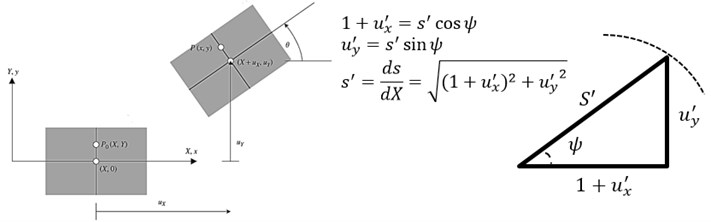
2.1. Kinematics of total Lagrangian Timoshenko fiber-based model
In this research the general formulation of total Lagrangian (TL) kinematics is used to derive the finite element equations of a two-node Timoshenko plane beam element. Formulations are implemented based on Timoshenko model with local first-order shear deformation effects. Also, theory can account for geometrically nonlinear behavior due to large displacements and rotations beside material nonlinearity due to constitutive behavior of each fibers. Under the assumptions of the Euler-Bernoulli beam, the following relations can be obtained as Eq. (1). and are the displacements of the projection of on the neutral axis in the system. In addition, represents the rotation of the cross-section, as the arc length along the neutral axis in the current configuration and primes denote the derivatives with respect to as shown in Fig. 1.
Fig. 1Coordinates and elemental kinematics in the TL formulation
The deformation gradient matrix and displacement gradient matrix are derived from Eq. (1):
Strain-displacement relations can be written according to Eq. (1) and the plane portion of the Green-Lagrange (GL) strain tensor () is obtained. In the following, a consistent-linearization technique is used by definition an orthogonal matrix . Therefore, the Green strain matrix can be rewritten and replaced by the simpler form as Eq. (2):
Hence, the axial strains and shear strains can be arranged in a strain vector (Eq. (3)):
In the following, strain displacement relation can be obtained by nodal displacement variations:
Using the shape functions of the reference element, the discretization of the variables is performed. The elements with distributed nonlinearity were formulated with the classical stiffness method using cubic Hermitian polynomials to approximate the deformations along the element. According to Hermite interpolation the degrees of freedom for each element are the displacements in orthogonal directions and slopes at the two nodes:
where is presented as shear slenderness which defined as Eq. (6):
where is defined as shear stress correction factor which assumed 0.833 for rectangular sections. The variable is shear modulus obtained by a subroutine program based on local stress field direct analysis which detailed explanation is given in Section 3.
The is the matrix giving the generalized strains according to nodal displacements in each loading step. It is essential to compute sectional resistance force based on the given stress of the fiber state. The section resistance forces are computed from the fiber stress distribution and section stiffness is assembled from the fiber stiffnesses. This force is implemented according to Eq. (7), and the following stages lead to the calculation of element resistance force:
Based upon an Total-Lagrangian approach, the incremental matrix equilibrium equation for a system can be formulated using the variation of the increment of total potential energy and governed equations are simplified as:
where and are the stiffeness of fiber planar Timoshenko frame element due to material nonlinearity and geometrical nonlinearity, respectively:
3. Interface element implementation
A basic interface element which is consisted three springs at each pairing of mating nodes is based on beam column degrees of freedom. Springs are separated in classification of axial, rotating and shear stiffness which is represented the interface behaviors. The stiffness matrix has the following shape:
where , , and are stiffness of springs in shear, axial, and moment, respectively. The shear stiffness is earned through relative tangential displacements between the two nodes from displacement vector in the local coordinate and local stress field direct analysis approach (See Section 3).
4. Constitutive law in total strain form
Under uniaxial tension-compression or biaxial compressive stress state of the material, nonlinear material characteristics are considered [8-10]. In the RC structures, the constitutive relation in the uncracked state is restricted to linear elasticity. The constitutive shear model is adapted according to Li [11] which was developed for modeling the nonlinear behavior of concrete elements. In this paper, local stress field theory based on fixed smeared crack approach is implemented in the subroutine of the program. Some details can be found in [12]. Nonlinear element analysis is used in the form of a subroutine in the main program, and these local interface elements are assembled along with fiber beam column elements. Local analysis is performed in each computational step state. The nonlinear behavior of the element can be obtained using an iterative solution method by applying in-plane incremental stresses or strains with secant elasticity modulus as Eq. (12). The analytical process is executed by implementation of direct displacement control that was introduced by Jirásek and Bazant [13]:
Based on mentioned scheme, the applicability of chosen model for different types of structures with arbitrary constitutive behavior is implemented.
5. Numerical implementation and solution
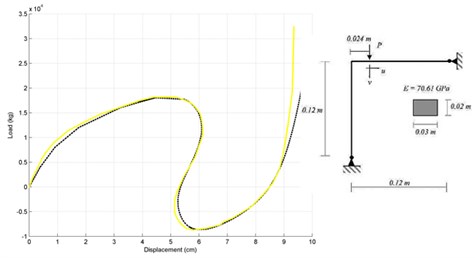
Some numerical examples are used to verify the accuracy and show the efficiency of the proposed geometrically nonlinear frame element as well as the solution marching schemes. The iterative-incremental method (Arc-Length method) with a variable stiffness scheme was applied to analyze structures. Afterward, several numerical investigations were performed with the proposed model in order to study the effects of nonlinear shear deformations and flexural responses, simultaneously.
Fig. 2Load-vertical displacement responses of cantilever beam
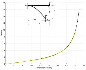
Fig. 3Load-vertical displacement responses for Williams’ Toggle frame
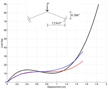
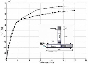
The results of the nonlinear computer analyses are compared with the observed data and analytical results. These examples are considered as “classic” benchmark since some of them have been widely used by several researchers to evaluate their nonlinear frame models. At first, A cantilever beam subjected to an end-point load [14] shown in Fig. 2, Williams’ Toggle frame [15] (Fig. 3) and Lee et al. frame [14] (Fig. 4) are employed.
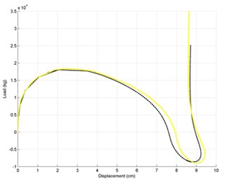
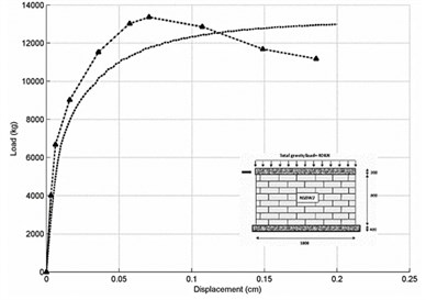
The ability of the proposed method to predict the nonlinear behavior of the structures is validated in this section by comparing the analytical and experimental results of the tests performed by Yaghoubifar’s rehabilitations [16] and Chun and Kim’s RC joint connection [17]. The SSBW2 was strengthened on one side of the masonry wall with concrete.
Fig. 4Load-displacement responses for Lee et al.’s frame: a) load-vertical displacement diagram and b) load-horizontal displacement diagram
a)
b)
Fig. 5Load-displacement responses for strengthened masonry walls a) SSBW2 and b) Chun and Kim’s RC joint connection
a)
b)
6. Conclusions
In this paper, the ability and accuracy of the proposed element is illustrated to model a fiber beam-column experiencing considerable large displacements compared to its initial length and showing unlimited hardening behavior which can account for different kinds of fiber constitutive materials (Steel, Masonry, Concrete). The fiber beam-column model proposed in this paper is based on distributed plasticity techniques. The advantage of the distributed-plastic over the plastic-hinge method is its accuracy in defining the plastic zone during the analysis. Moreover, a new formulation to attain the shear response along with flexural behavior for any load cases is suggested as local stress field model implemented in interface elements based on the fixed smeared crack approach. The proposed model was calibrated and validated through a comparison with experimental results and various numerical analyses were performed in order to study the influence of nonlinear flexural-shear interaction. Thereafter, this method could yield accurate and convergent results in agreement with the problems.
References
-
Crivelli L. A., Felippa C. A. A three‐dimensional non‐linear Timoshenko beam based on the core-congruential formulation. International Journal for Numerical Methods in Engineering, Vol. 36, Issue 21, 1993, p. 3647-3673.
-
Dvorkin E. N., Onte E., Oliver J. On a non‐linear formulation for curved Timoshenko beam elements considering large displacement/rotation increments. International Journal for Numerical Methods in Engineering, Vol. 26, Issue 7, 1988, p. 1597-1613.
-
Zhang L., Xu G., Bai Y. Fiber model based on Timoshenko beam theory and its application. Advanced Science Letters, Vol. 4, Issues 4-5, 2011, p. 1886-1888.
-
Kabeyasawa T., Shiohara H., Otani S., Aoyama H. Analysis of the full-scale seven-story reinforced concrete test structure. Journal of the Faculty of Engineering, University of Tokyo, Vol. 37, Issue 2, 1983, p. 431-478.
-
Vulcano A., Bertero V. V., Colotti V. Analytical modeling of RC structural walls. Proceedings of 9th World Conference on Earthquake Engineering, Vol. 6, 1988, p. 41-46.
-
Ghaisas K. V., Basu D., Brzev S., Pérez Gavilán J. J. Strut-and-tie model for seismic design of confined masonry buildings. Construction and Building Materials, Vol. 147, 2017, p. 677-700.
-
Bocciarelli M., Barbieri G. A numerical procedure for the pushover analysis of masonry towers. Soil Dynamics and Earthquake Engineering, Vol. 93, 2017, p. 162-171.
-
Maekawa K., Okamura H., Pimanmas A. Non-Linear Mechanics of Reinforced Concrete. CRC Press, London, 2003.
-
Vecchio F. J., Collins M. P. The modified compression-field theory for reinforced concrete elements subjected to shear. Journal of the American Concrete Institute, Vol. 83, Issue 2, 1986, p. 219-231.
-
Zhuge Y., Thambiratnam D., Corderoy J. Nonlinear dynamic analysis of unreinforced masonry. Journal of Structural Engineering, Vol. 124, Issue 3, 1998, p. 270-277.
-
Li B. Contact density model for stress transfer across cracks in concrete. Journal of the Faculty of Engineering, the University of Tokyo, Vol. 40, Issue 1, 1989, p. 9-52.
-
Jahanmohammadi A., Soltani M. Toward combined local-average stress field modeling of reinforced concrete. Engineering Structures, Vol. 111, 2016, p. 394-410.
-
Jirásek M., Bazant Z. P. Inelastic Analysis of Structures. John Wiley and Sons, 2002.
-
Limkatanyu S., Prachasaree W., Kaewkulchai G., Spacone E. Unification of mixed Euler-Bernoulli-Von Karman planar frame model and corotational approach. Mechanics Based Design of Structures and Machines, Vol. 42, Issue 4, 2014, p. 419-441.
-
Williams F. An approach to the non-linear behaviour of the members of a rigid jointed plane framework with finite deflections. The Quarterly Journal of Mechanics and Applied Mathematics, Vol. 17, Issue 4, 1964, p. 451-469.
-
Yaghoubifar A. Experimental and Analytical Investigation on the Behavior of Strengthened Brick Walls by Steel Bars and Concrete. M.Sc. Thesis, Tarbiat Modares University, Tehran, Iran, 2008.
-
Chun S.-C., Kim Year D.-Y. Evaluation of mechanical anchorage of reinforcement by exterior beam-column joint experiments. Proceedings of 13th World Conference on Earthquake Engineering, 2004.
About this article

