Abstract
Different kinds of artifacts can occur during a magnetic resonance imaging (MRI) scans due to hardware or software related problems, human physiologic phenomenon or physical restrictions. Some of them can seriously affecting diagnostic image quality, while others may simulate or be confused with different pathology. On another word artifact as an artificial feature appearing in an image that is not present in the original investigative object. It is important to recognize these artifacts according to a basic understanding of their origin, especially those mimicking pathology, as they can lead to incorrect diagnosis and cause serious after-effects on patient’s health and outcomes. We presented an overview of the most common MRI artifacts and methods to fix or rectify them. We also provide the original artifacts images and statistics from the Lithuanian University of Health Sciences Kaunas Clinical Hospital, Dept of Radiology, mainly obtained from image databases and some images from data base of other Lithuanian hospitals.
1. Artifacts in magnetic resonance imaging
Since 1973, when Paul Lauterbur extracted the first Magnetic Resonance Image (MRI), this technology has greatly advanced. MRI has become a powerful and widely accessible imaging type in diagnostic radiology. Since MRI is sensitive to the chemical surroundings of the atomic nuclei within the body, the images have excellent contrast between different soft-tissues [1]. MRI used for nervous, muscle-skeletal system, cardiovascular and other systems clinical investigation because of good soft tissue contrast and high spatial resolution. Consequently, of its unique sensitivity spectrum of physiological and biological parameters such as flow, chemical composition and molecular configuration MRI is also suitable for functional and metabolic studies. The examination has a huge possibility in choosing the imaging settings: tissue contrast, image resolution and anatomical coverage may be optimized for a specific use. Both two-dimensional (2D) and three-dimensional (3D) images can be formed without image orientation restrictions. Probably the most important thing is that MRI does not involve the use of ionizing radiation, its safe for continuous comparable investigation. MRI signal is generated by a strong magnetic field which is committed by superconducting coil, one or more radiofrequency fields and several weaker magnetic fields generated by the three gradient coils combinations [2].
Like any other type of diagnostic imaging, MRI is also susceptible to artifacts. They arise because of the breach of one or more imaging principles of assumptions. Often, several different kinds of artifacts occur only in single image or sequence. Though a few of artifacts can be avoided by using an appropriate scanning techniques even customized scanning protocols with well-maintained and calibrated systems will not prevent all of them. As a result, series of corrective procedures was developed in order to eliminate or to reduce artifacts. Typical artifact correction methods are: improvement of technical equipment, optimization of scanning parameters and pulse sequences and image processing after the scanning procedures. Below we will discuss the most common types of artifacts, their causes and correction methods. Identification of artifact type and etiology is important in developing reliable scanning protocols, pulse sequences and data processing algorithms [2].
2. What is an artifact?
There is no unanimous or standard definition of a MRI artifact in literature. It has happened so because of abundance of artifacts and partially due to the fact that in some situations the artefact can be harmful to image diagnosis, meanwhile in other it can be even useful. For example, due to a magnetism or sensitivity variations of some materials, artifacts of blurring and signal loss may develop, however, due to hemoglobin oxygenation induced by sensitivity differences, a signal subject to the amount of oxygen in blood develops and is used in functional MRI diagnostics [3]. Phase contrast methods is another example: additional signal phase terms generated by blood stream may produce imaging artifacts, but it also gives a possibility for measurements of phase susceptible velocity, important for assessment of organs blood flow in MRI images [4]. It would be acceptable for us such definition of the artefact as any content or object of the image, which does not coincide with the arrangement of the scanned object or occasional noise.
Table 1Main reasons behind the artifact formation
Technical problems | e.g., calibration, voltage instability |
Software problems | e.g., programming errors |
Physiological phenomena | e.g., blood flow, movement of the patient |
Physical limitations | e.g., Gibbs phenomenon, ferromagnetic foreign bodies |
3. Artifact types
3.1. Movement artifacts [5]
A movement is a principal source of MRI image artifacts. The name already suggests that movement artifacts are produced by movements of the object or its parts during an examination. Any movement causes two effects in MRI images. “View-to-view” effects are generated by a movement, which arises between successfully taken phase-encoding steps. Unstable localization of rotations made during data reception and intensity of the signal condition often generates errors. In the case of periodic movements, i.e. of a stable model, the result is a complete or partial repetition of moving tissues, so called “ghosting” artifacts. Such artifacts in the images are detected in the frequency coding direction, regardless of the direction of the movement. Periodical physiological movements generating “ghosting” artifacts are movements of the heart, breathing, pulsation of blood vessels and pulsation of brain liquids [6].
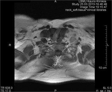
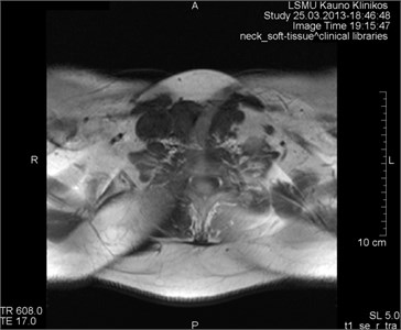
Movements appearing between excitation of radio frequencies and echo reception (“within-view”) evokes a deficit of the coherent phase between moving rotations in the period of echo formation [7]. Such incoherence manifests as fading or increased noise in the images. Contrary to the phase errors, manifesting under effect of “view-to-view” movements, the “within view” effect evidences throughout the entire image. Most frequently, it is related to a random movement, which may reveal itself during intestine peristaltic, swallowing, cough, eye movement and perceptible movements of the patient (Figs. 1 and 2) [8].
3.1.1. Breathing
Breathing movement condition ghosting artifacts and blurring, which can cover or simulate pathological lesions. Numerous different methods have been tested to reduce breathing movement artifacts.
Artifact correction [5, 9]:
– Breath holding;
– Sedation, anesthesia;
– Mechanical methods, such as abdomen or chest immobilization or examination performed by keeping the patient on the abdomen to reduce the amplitude of breathing movements. However, the later attempts could cause a discomfort for the patient and might produce a negative effect;
– “Signal averaging” means gathering of repetitive data and using it to improve “signal-to-noise” ratio. Manifestation of “ghosting” artifacts in the process is decreased by the square root of the average number of the signals (approximately). Yet the examination period also increases depending on the count of obtained averages;
– “Breathing triggering” means data gathering only throughout a part of the breathing cycle, most frequently, at the end of exhalation, when breathing movements are minimal. The extended examination period is a bottleneck of the method, as some time is consumed unproductively, waiting for a moment suitable for the scanning;
– Use of “gradient moment nulling” is the application of additional gradient sequences, seeking to rectify phase shifts between the response of moving protons at the time of return. This method enables to rectify movements with stable velocity, to decrease signal losses and ghosting related to such movements. Also, this method allows to avoid long image production;
– Another method to decrease signal intensity from moving tissues is using “fat suppression” sequences. This method suppresses the signal from fat not only in hypodermal layer of the skin, but also on mediastinum, mesentery, retroperitoneal and other internal fat collections, therefore, less ghosting artifacts are produced.
Fig. 1MRI axial projection. Extensive movement artifacts are observed due to the patient movement: a) 2 years old child, b) same child patient, different slice
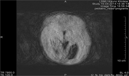
a)
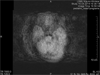
b)
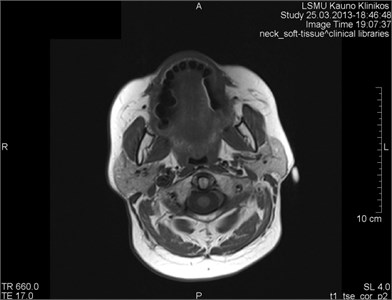
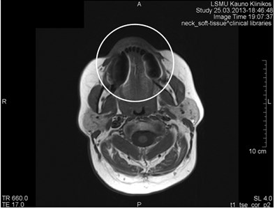
Fig. 2Movement artifacts are observed due to the eye balls movement (marked by arrows)
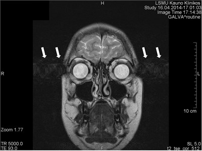
a) MRI coronal projection
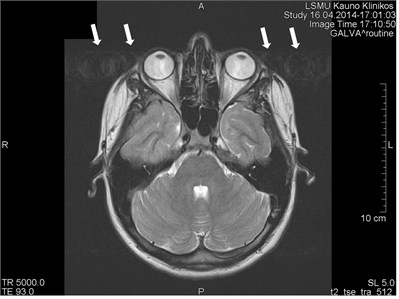
b) MRT axial projection
3.1.2. Heart movements
Heart movements produce series of ghosting artifacts in the phase coding direction, which determine fading of the heart and neighboring structures and signal loss in the images [10].
Artifact correction [5]:
– The main correction method is electrocardiographic “trigger”. Data collection is synchronized with the labor phase of the heart. Such synchronization enables heart tissue to remain in a stable position, which preconditions an improved signal intensity from the heart and a lower number of phase errors;
– Use of “fast sequences”, which decrease a movement probability at the time of data gathering;
– Use of “gradient moment nulling” and “spatial RF pre-saturation”.
3.1.3. Pulsation of blood vessels
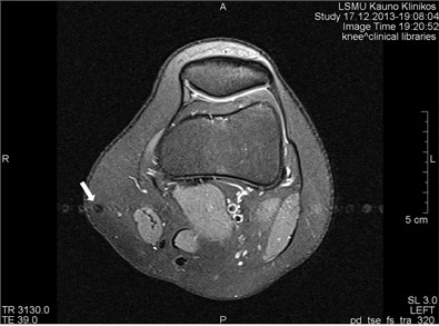
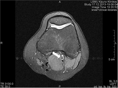
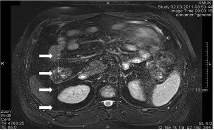
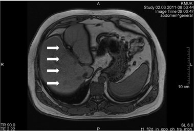
Blood vessels pulsation artifacts can be recognized from their location in the vicinity of a relevant blood vessel in the phase coding direction. Such pulsation produces artifacts equal in size and shape of the blood vessel profile, although not necessarily of the same signal intensity (Figs. 3 and 4) [5].
Fig. 3a) MRI axial projection. The pulsation artifact, which can be easily confused with nearby blood vessels or lesions (marked by an arrow). b) A clearly seen artifact imitating anatomic structures is not visible in the next cross-cut. A blood vessel, from which pulsation artifacts are visible extending horizontally to both sides, is marked by an arrow
a)
b)
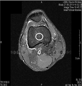
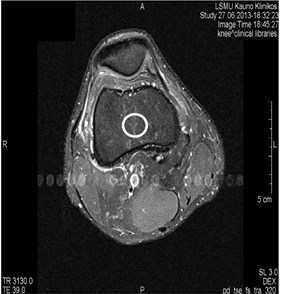
Fig. 4MRI axial projections. Pulsation artifacts are visible extending in a horizontal line from the blood vessel (marked by circles)
a)
b)
Artifact correction [11]:
– “Cardiac gating” is a selective choice of cardiac function information in relevant portions of the cycle, using data from the electrocardiograph signal to determine a precise heart cycle and control image selection;
– “Flow compensation” decreases pulsation artifacts by adding an extra gradient and removing phase differences for motionless and moving rotations at the time of response;
– Application of “saturation bands” or “fat suppression” methods is another way to decrease movement artifacts by suppressing a signal from moving tissues;
– Changing the phase of encoding direction.
3.2. Chemical shift artifacts
Chemical shift phenomenon is also known as “misregistration” or “mismapping” [12]. Such artifacts emerge from the chemical shift margin between fat and water. Such artefact manifests as incorrectly registered fat and water pixels in the image. The obtained effect as fat and water rotations in the same voxel are coded as if localized in different voxels. The artifacts of the chemical shift are most frequently detected in the frequency encoding direction; however, they can also manifest along the cross-cut direction. They are more intensive where the magnetic field is stronger and mostly visible in the bodies of the vertebrae, sockets of the eye and solid bodies surrounded by fat. Artifacts are more frequently visible in T2, less in T1 sequences [5, 11].
Artifact correction [5, 11]:
– For the artifact reduction, a higher permeability of the receiver, a selection of a larger matrix, phase TE or “spin-echo” (SE) sequences can be employed;
– A larger gradient can be used to decrease limits of the chemical shift;
– By using special pulse sequences, such as fat saturation or inversion recovery;
– Fat suppression technique eliminates chemical shift artifacts, which are produced due to the deficit of a fat signal;
– By decreasing the voxel size;
– A MRI device with a weaker magnetic field can be employed for the examination, but it’s not recommended.
3.3. Susceptibility or metal artifact
Susceptibility artifacts can be provoked by microscopic gradients or variations in the magnetic field, which forms in the vicinity of interactions between substances with different magnetic susceptibility. Factors that influence the production of metal-related artifacts at MRI imaging include the composition, size, and orientation of the metallic object with regard to the direction of the external magnetic field; the type of pulse sequences applied; and the sequence parameters, including magnetic field strength, voxel size (determined by field of view, image matrix, and section thickness), and echo train length [13].
The nature of the materials varies widely, and distinction must be made between MR-compatible and incompatible materials. A majority of supportive lines, tubes, and catheters are composed of non-ferromagnetic materials, such as polyvinyl chloride (plastic) and are virtually invisible on MRI [14]. Metallic biomedical implants composed of titanium, tantalum, and nitinol have also been shown to be nonferromagnetic and MR-compatible [15]. However, both ferromagnetic and non-ferromagnetic materials induce artifacts [16]. Artifacts with a high susceptibility are most frequently visible around ferromagnetic objects inside diamagnetic materials (such as a human body). Such gradients cause exit of rotations from the phase and frequency alterations in the surrounding tissues. As a result, light and dark spots with a spatial distortion in the neighoring anatomic structures are seen (Figs. 5-8). The magnetic susceptibility effect is increased with the magnetic field strength, leading to a greater impact on image spatial encoding and contrast formation [17]. Such artifacts are the brightest in the long echo and gradient echo (GE) sequences of the gradient response [5].
Artifact correction [5, 18, 19]:
– Removal of ferromagnetic foreign bodies;
– Application of smaller voxels;
– Shortening the response time;
– Using shorter echo time (TE). The artifact was smallest with 10 ms TE;
– Amplification of the receiver permeability;
– GE and echo-planar sequences must be avoided, as they emphasize susceptibility artifacts;
– SE (especially fast SE) sequences can be employed;
– Avoid fused light bulbs because impurities in filament can lead to artifacts;
– A MRI device with a weaker magnetic field can be employed for the examination, but it’s not advisable to do that.
Fig. 5MRI axial projections. The metal artifact triggered by a dental crown is visible (marked by a circle)
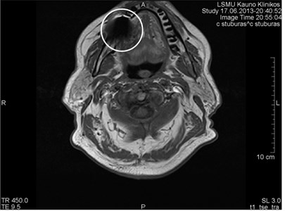
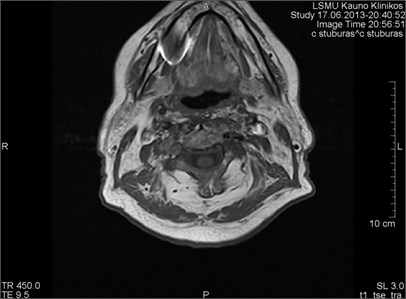
Fig. 6MRI axial projections. Numerous metal artifacts are visible in the dental projection (marked by a circle)
a)
b)
3.4. „Zipper“ artifact
Reasons triggering “zipper” artifacts in the images are very different. Most of them are related to technical or software errors, which have nothing to do with the technologist’s work. “Zipper” artifacts, which can be easily controlled, are those provoked by an accidental radio waves (RW) entering the scanning room if the door is open during the examination (Fig. 9) [5]. RWs from transmitters are likely to cause “zipper” artifacts, which are perpendicularly orientated to the frequency axis in the image. The broad wave noise corrupts the entire image, meanwhile narrow frequency noise triggers linear bands crosswise to the phase encoding direction [5]. If the interfering signal has a further, low frequency component (e.g., flickering light bulbs in the scanner room), the result may be a spike within the MR image [20].
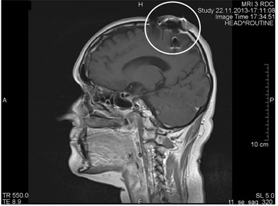
Fig. 7a) MRI axial projections. Artifacts triggered by foreign bodies are visible in the vertex projection. b) Same patient. MRI sagittal projection. Artifacts triggered by foreign bodies after the operation (marked by a circle)
a)
b)
Fig. 8a) MRI sagittal projection. The artifact is visible after a break of the puncture needle (marked by a circle). b) A MRI axial section. Same artifact visible on another projection (marked by a circle)
a)
b)
Fig. 9MRI axial projection. a) The patient took two cell phones into the scanning room. One was left in the vault; the other was inadvertently taken by a patient. There was a call during the scanning process which produced vertical “zipper” artifacts (marked by arrows). b) Same patient, T1 sequence. “Zipper” artifact is marked by arrows
a)
b)
Artifact correction [5]:
– Identification and removal of sources emitting RWs;
– Always closing scanning room doors;
– Hermetic inspection of the room with MRI equipment.
3.5. Black boundary artifacts
It’s an artificial black line at the fat and water surfaces, such as a fat and muscle junction. It appears in a TE sequence, when fat and water rotations in the same pixel are outside the phase boundaries – in this way they interrupt the signal of each other. It is very often visible in GE sequences in both directions (frequency and phase). In the images made by a magnetic tomography machine of 1.5 Tesla, they may appear approximately at a time of 2.3 ms [17].
Artifact correction [17]:
– „In-phase” TE sequences recommended;
– Using of „fat suppression “sequences;
– Increased permeability or matrix capacity are recommended.
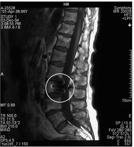
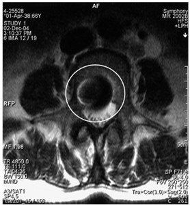
3.6. „Slice overlap “artifacts
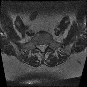
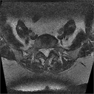
It’s a loss of the signal visible in the multi-sectional images, usually produced by scanning lumbar section of the spine. If slices are produced from different places of the intervertebral disc, they can overlap. If both levels are produced at the same time, e.g. L4-L5 and L5-S1, then the level, which is second in turn, will contain rotations, which have been already made so a signal loss band is produced, which cross the image horizontally and are the brightest in the back portion (Fig. 10). Slice overlaps should be avoided in the regions which may consist pathology [5].
Artifact correction [11]:
– Avoid sharp angle changes between slice groups;
– Increase a gap between slices;
– Apply different storage processes for images;
– GRE sequences are expedient.
Fig. 10MRI axial projections. Visible slice overlap
a)
b)
3.7. Aliasing artifacts
They appear when the field of visibility (FOV) is lower than the scanned portion of the body, which makes the surplus portion to project on another part of the image (Fig. 11). They are triggered by an insufficient selection (in the phase period) or in some cases by the frequency direction. They may develop making last 3D slices [17].
Artifact correction [17]:
– Increase FOV (resolution decreases);
– Data selection increase in the frequency direction (standard) and gradual phase increase in the phase decoding direction – phase compensation (time or Signal to Noise Ratio loss);
– Alteration of the phase and frequency direction as to make the phase in the narrower direction;
– Application of the surface coils to avoid signal behind FOV boundaries.
Fig. 11MRT axial projections. The aliasing artifact is visible
a)
b)
3.8. Gibb’s artifact
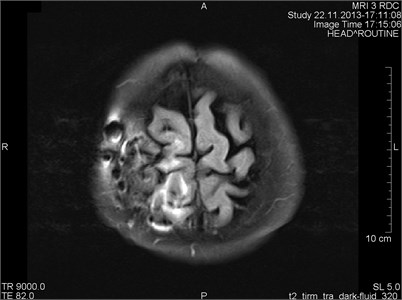
Gibb’s, aka ringing or truncation, artifact looks like a series of lines in the MR image produced in the object of parallel steep or intensive alterations (Fig. 12). Such artifact is not clearly visible in plain objects. The artifact is triggered by Gibb’s phenomenon, i.e. ringing appearing at the rupture of the Fourier sequence. Truncation artifacts are common in the spine due to sharp signal changes
between cord and cerebrospinal fluid (CSF) [21]. The artifact in spinal cord can simulate a small fistula. Gibb’s artifacts can also be visible in the parts of the cranium/cerebrum. The larger number of decoding steps, the less intensive and thicker Gibb’s artifact is.
Artifact correction:
– The problem can be resolved with softening filters (LanczosSigmaFactor, 2-D exposure filtration, Gegenbauer reconstruction, etc.);
– Use of a larger acquisition matrix;
– Use of a smaller FOV.
Fig. 12MRT sagittal projections. Ringing artifacts are visible
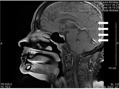
a)
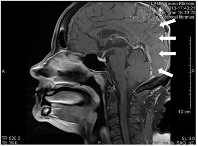
b)
4. Our personal experience
4.1. Methodology
4 experienced radiologists (10 or more years work in University hospital) and 1 radiology resident retrospectively re-evaluated 663 MRI series from Lithuanian University of Health Sciences Clinical Hospital image database from 2013-01-01 to 2016-01-01 for artifacts.
4.2. Results
There was total of 514 examined patients, women accounted for 58 % (296 patients), men 42 % (218 patients). Artifacts were detected in 252 patients, women accounted for 58 % (145 patients), men 42 % (107 patients).
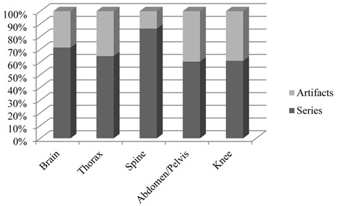
From the total MRI series examined (663), artifacts were found on 252 series (Fig. 13). This represented 38 % of all MRI series. The most common types of artifacts were: movement induced artifacts (38 %), Gibb’s artifacts (25 %), metal (18 %) and slice overlap artifacts (12 %). Other, rare types of artifacts, represented 6 % of all artifacts (Fig. 14). Most commonly, in 31 % of cases, artifacts were found in brain studies. Artifacts were reported in 25 % of abdomen/pelvis examinations, 15 % on knee examinations, 10 % on spine examinations, and in 10 % of cases in chest (including heart) studies. 9 % of artifacts were found in different organ system studies.
Artifact percentages in frequently scanned portions of the body are on Fig. 15.
Fig. 13All artifacts found 252/663 series
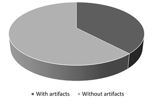
Fig. 14MRI artifacts by type
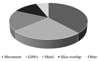
Fig. 15Artifact percentages in frequently scanned portions of the body
5. Conclusions
1) Artifacts are common in medical imaging and very common in MRI;
2) Most common MRI artifacts were movement, Gibb’s, metal and slice overlap artifacts;
3) It is essential to recognize artifacts and noise factors in MRI in order to maintain high diagnostics quality;
4) Recognizing them is essential for image interpretation and selection of an appropriate artifact correction method;
5) The best way to remove some artifacts is to avoid them, use up to date and well calibrated scanning hardware together using appropriate pulse sequences and gating methods;
6) If artifacts are inevitable, artifact-insensitive or artifact-correcting pulse sequence, image-processing algorithms, and scan protocols should be used.
References
-
Siversson C. Basic MRI Physics and Artifacts. Hip Magnetic Resonance Imaging, Springer, New York, NY, 2014.
-
Firmin D. N., Nayler G. L., Kilner P. J., Longmore D. B. The application of phase shifts in NMR for flow measurement. Magnetic Resonance in Medicine, Vol. 14, Issue 2, 1990, p. 230-241.
-
Saloner D. Flow and motion. Magnetic Resonance Imaging Clinics of North America, Vol. 7, Issue 4, 1999, p. 699-715.
-
Barish M. A., Jara H. Motion artifact control in body MR imaging. Magnetic Resonance Imaging Clinics of North America, Vol. 7, Issue 2, 1999, p. 289-301.
-
Gonçalves S. I. Artifacts in MRI Identification, Explanation, Solution. Radiology Department, University Hospital Coimbra, 2011.
-
Hedley M., Yan H. Motion artifact suppression: a review of post-processing techniques. Magnetic Resonance Imaging, Vol. 10, Issue 4, 1992, p. 627-635.
-
Chun Ruan MRI Artifacts: Mechanism and Control. Diagnostic Imaging II, Student Project Reports 2003.
-
Huber M. E., Hengesbach D., Botnar R. M. Motion artifact reduction and vessel enhancement for free-breathing navigator-gated coronary MRA using 3D k-space reordering. Magnetic Resonance in Medicine, Vol. 45, Issue 4, 2001, p. 645-652.
-
Lipton M. L. Artifacts: when things go wrong, it’s not necessarily all bad. Totally Accessible MRI. Springer, New York, NY, 2008.
-
Mugler J. P. 3rd. Overview of MR imaging pulse sequences. Magnetic Resonance Imaging Clinics of North America, Vol. 7, Issue 4, 1999, p. 661-697.
-
Magnetic Resonance – Technology Information Portal. http://www.mr-tip.com/serv1.php? type=art&sub=Black%20Boundary%20Artifact.
-
Singh D. R., Rumpel H., Chin M. S. M., Peh W. C. G. Magnetic Resonance Imaging Artifacts. Pitfalls in Musculoskeletal Radiology, 2017.
-
Stradiotti P., Curti A., Castellazzi G., Zerbi A. Metal-related artifacts in instrumented spine. Techniques for reducing artifacts in CT and MRI: state of the art. European Spine Journal, Vol. 18, Issue 1, 2009, p. 102-108.
-
Fowler K. J., Maxwell J., Saad N. E., et al. Magnetic resonance imaging of iatrogeny: understanding imaging artifacts related to medical devices. Abdominal Imaging, Vol. 39, Issue 2, 2014, p. 411-423.
-
Marshall M. W., Teitelbaum G. P., Kim H. S., et al. Ferromagnetism and magnetic resonance artifacts of platinum embolization microcoils. Cardiovascular Interventional Radiology, Vol. 14, Issue 3, 1991, p. 163-166.
-
Leclet H. Artifacts in magnetic resonance imaging of the spine after surgery with or without implant. European Spine Journal, Vol. 3, Issue 5, 1994, p. 240-245.
-
Yang Q. X., Smith M. B., Wang J. Magnetic susceptibility effects in high field MRI. Ultra High Field Magnetic Resonance Imaging, Biological Magnetic Resonance, Springer, Boston, MA, Vol. 26, 2006.
-
Minowa K., Abe S., Sawamura T., et al. A method of reducing susceptibility artifacts in MRI of the head and neck region. Oral Radiology, Vol. 13, Issue 1, 1997, p. 45-49.
-
Sen A. Unexpected MRI artifacts – experience from India. Pediatric Radiology, Vol. 45, Issue 11, 2015, p. 1722-1725.
-
Heiland S. From A as in aliasing to Z as in zipper: artifacts in MRI. Clinical Neuroradiology, Vol. 18, Issue 1, 2008, p. 25-36.
-
Artifacts and Errors in Breast Magnetic Resonance Imaging. Breast MRI, Springer, New York, NY, 2008.
Cited by
About this article

Tomas Budrys did most of literature research and statistical analysis, documentary work, cooperation with other authors. Vincentas Veikutis involved in documentary work, literature research (physics). Saulius Lukosevicius did statistical part, diagrams. Rymante Gleizniene did literature research (corrections of artifacts), MRI images evaluation. Egle Monastyreckiene did literature analysis, some MRI images evaluation, documentary work. Ilona Kulakiene did literature research and some of the statistical part, English language correction.
