Abstract
Most of the proposed methods for obtaining the free vibration natural frequency of the retaining wall assume the behavior of the wall in the two-dimensional domain, and they are not able to express the three-dimensional behavior of these structures in a satisfying manner. Moreover, the effect of damping has not yet been considered in analytical study. In this paper, the plate theory and Galerkin method is employed to analyze the free vibration of a wall-reinforcement-soil system in the three dimensional domain and survey the effect of damping on the natural frequency of a retaining wall. So, the retaining wall is modeled as a clamped-free plate and the stiffness of the soil and reinforcements existing behind the wall are modeled as a set of springs and the damping effect of the system is modeled by a set of dampers located at the back of the Retaining wall and attached to it. The results of the proposed model are compared with both the results of the other researchers and the ones from finite element method (FEM). They are also compared with the results of a full-scale experiment and it shows a good agreement. The proposed method which uses the plate theory, also yields the free vibration natural frequencies of the wall’s extensional modes with an acceptable accuracy. Finally, the effect of tensile and compressive behaviors of the soil and the reinforcements on the fundamental frequency of a reinforced retaining wall is studied.
1. Introduction
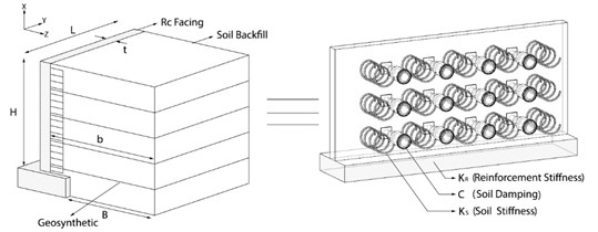
Geosynthetic-reinforced soil retaining walls represent one of the most applicable geosynthetic systems used in civil engineering due to their suitable seismic behavior. Thus, great effort has been put into analyzing these types of reinforced walls so far Koseki et al. [1]. In the early 1990s, researchers invented a reinforced retaining wall named geosynthetic-reinforced soil-retaining wall with full-height rigid concrete facing (GRS-FHR) Tatsuka et al. [2]. Fig. 1 shows a perspective view of a geosynthetic-reinforced retaining wall. After the Hygo-ken Numbu earthquake, researchers studied the seismic behavior of the GRS-FHR walls. The Tatsuka et al. [2], Tatsuka et al. [3] results showed very satisfying behavior of these reinforced soil walls compared with walls without reinforcement while facing the earthquake; thus, these walls were developed and used increasingly.
Fig. 1Schematic view of GRS-FHR wall Huang and Wang [4]
![Schematic view of GRS-FHR wall Huang and Wang [4]](https://static-01.extrica.com/articles/19638/19638-img1.jpg)
Various modeling techniques such as concentrated mass modeling was used to obtain the natural frequency of civil structures such as building structures and fluid storage tanks (Chopra [5]). However, continues mass modeling is suggested to attain more accurate results while modeling structures such as retaining walls. Two of the most important parameters affecting a distributed mass system’s behavior, such as a reinforced soil retaining wall, are soil-wall interaction and the interaction that exists between the reinforcements and the retaining wall, which have to be considered in both numerical and analytical modeling to achieve more precise results. There are lots of researches performed on the analytical solution of reinforced inextensible and extensible membrane in a half-space/full-space Shodja et al. [6], Selvadurai [7] and Ahmadi and Eskandari [8] and Ahmadi et al. [9]. Dynamic treatment of soil-structure interaction of an anchorage system have been studied by Selvadurai [10], Eskandari et al. [11] and Ahmadi and Eskandari [12], but considerable analytical method for modeling the interaction between reinforced soil and a wall and its effect on the natural frequency has not yet been proposed.
To date, all analytical proposed methods are based on the 2D modeling of wall-soil systems, which completely ignores the in-depth transverse vibration modes and neglects the different behaviors of reinforcements and soil under tension and compression in the 3D domain. Thus, the results obtained from these methods are less accurate.
In this paper, the free vibration frequency of a reinforced soil retaining wall is analyzed in the 3D domain by invoking the plate vibration theory. The interactions between the wall, soil and reinforcements are also considered using axial springs. The effect of the system’s damping is considered using dampers. The different behaviors of the reinforcements and soil are considered in this analytical procedure; therefore, the tensile behavior of the soil and compressive behavior of the reinforcements are excluded in this study to achieve more realistic results using the expression presented in Chati et al. [13]. Also, the effect of the system’s damping on the natural frequency of a reinforced retaining wall is considered using the Galerkin method and new analytical expressions for obtaining the first three damped natural frequencies of the geosynthetic reinforced soil walls are proposed. The main purpose of this paper is to provide a 3D analytical expression for estimating the free vibration frequencies of reinforced soil walls by considering the real behaviors of the soil and reinforcements and investigating the effect of the system’s damping on it. Nevertheless, the model can be extended to evaluate seismic responses during forced vibration analyses.
2. Review of past studies
Many different methods have been introduced to analyze the seismic behavior and investigate the free vibration natural frequency of reinforced and non-reinforced retaining walls, including numerical, analytical and experimental methods. Matsu and Ohara [14], Wood [15], Scott [16] and Wu [17] proposed an analytical expression to calculate the fundamental frequency of a wall based on two parameters: backfill height and backfill shear wave velocity. Matsu and Ohara [14] defined two boundary limits and claimed that the main procedure is located between these two limits. Wood [15] proposed an applicable method for calculating the fundamental frequency of the embedded soil between two rigid retaining walls, which essentially involved solving a boundary condition problem. Scott [16] calculated the fundamental frequency of a wall by modeling the wall as a shear beam and attaching it to a Winkler spring. Yeh [18] also considered the translational and rotational vibration modes by invoking a model similar to that of Scott [16] and used the Galerkin method to solve the partial differential equations of the wall. Rigidity of the wall is an important and substantial base of all the methods mentioned above, which are based on shear beam theory. Thus, Jain and Scott [19] inserted the wall’s flexibility into their calculations. Generally, most of the analytical models proposed so far are in the 2D domain. In these models, interaction between reinforcements and the wall is completely neglected or there is no difference between the tension and compression behavior of the reinforcement.
Elgamal et al. [20] studied the 3D behavior of a wall by instrumenting the retaining wall and recording the responses of the soil-wall system to a wide range of exciting frequencies. They used the finite element method to model the wall and compared the results obtained with those of the experiments, which showed that walls with varying height through the length of it have resonance frequencies that appear in the length of the wall. Also, Elgamal et al. [20] estimated viscose modal damping using the half-power bandwidth method [21]. The damping ratio estimated from half-power bandwidth method varied from 6.6 % to 15 %. They finally concluded that it is better to analyze the soil-wall system in the 3D domain while calculating the fundamental frequency.
Bathurst and Hatami [22], Hatami and Bathurst [23], EL-Emam and Bathurst [24], Zarnani et al. [25], Ehrilch and Mirmoradi [26], Wang et al. [27], Balakrishnan and Viswanadham [28] and Yazdani et al. [29] used numerical modeling and experimental testing of a geosynthetic reinforced soil retaining wall to analyze the effect of parameters such as wall height, soil backfill width, reinforcement stiffness and length, internal friction angle of the backfill, damping ratio and toe abutment condition on the seismic behavior of the wall. However, they also showed the magnitude of amplification was influence by magnitude of damping ratio used in numerical modeling. The selection of Rayleigh damping coefficients for the soil was investigated by Ling et al. [30] who determined that for models with a peak acceleration of 0.4 g, a 15 % and for models with maximum acceleration of 0.8 g, a 5 % damping value produced the most satisfactory results.
The results showed that the fundamental frequency of a reinforced soil wall with wide backfill can be calculated with acceptable accuracy using the analytical expressions based on wall height and the domain shear wave velocity. They also showed that the effect of reinforcement stiffness and length and toe abutment condition on the fundamental frequency of the wall is negligible Hatami [23]. Bathurst and Hatami [31] and Hatami and Bathurst [32] studied input ground motion, especially the effect of the uniform vertical ground motion and rocking ground motion, on the dynamic behavior of a geosynthetic reinforced soil retaining wall. In the field of dynamic behavior of plates on elastic media, Selvadurai [33, 34] and Eskandari and Ahmadi [35] studied dynamic behavior of surface-stiffened elastic half space.
Ghanbari et al. [36] proposed an analytical expression for calculating the fundamental frequency of a retaining wall by modeling the wall as a beam and modeling the soil as a set of parallel springs and by invoking the approximate Rayleigh method. Abbasi et al. [37] used the Rayleigh method, modeled the reinforcements as tensional springs to study the effect of the reinforcements on the fundamental frequency of the reinforced soil wall and proposed an analytical expression to calculate its fundamental frequency.
Ramezani et al. [38] investigated the effect of the foundation on the natural frequency of rigid and flexible modes of GRS-FHR walls by using the Rayleigh-Ritz method. In their study, the effect of rocking and translational vibration on the fundamental frequency of the GRS-FHR wall was considered. In their study, because of the 2D analysis, in-depth transverse modes were neglected and the different behaviors of the soil under tension and compression were ignored.
Darvishpour et al. [39] studied the natural frequencies of a retaining wall without reinforcement in 3D domain by invoking the plate theory and Rayleigh quotient. They showed that by using the plate theory length modes are discovered and they showed that the second and third modes are longitudinal modes while by beam theory the second and third modes are altitudinal modes and they proposed analytical formula for the first three modes of the wall.
Numerous investigations have also been conducted to study the dynamic behavior of the reinforced soil-wall systems and plate vibration including: Li and Aguilar [40], Gazetas et al. [41], Lanzoni et al. [42], Tang and Yeh [43], Mojallal et al. [44], Chen et al. [45], Liu et al. [46] and Shi and Rehman [47].
In all studies which is done by other researchers, there is no analytical solution for estimating 3D natural frequency of reinforced retaining wall and also there is no analytical solution for considering the effect of system damping on natural frequency of retaining wall.
3. Theory and assumption
Some assumptions are considered in this study for obtaining the first three damped natural frequency of reinforced retaining wall based on Galerkin method as follow:
1) The retaining wall is assumed to be clamped-free, flexible and with a constant cross-section area.
2) The backfill is granular, dry, massless and with a constant Young’s modulus throughout the entire layer length. Most researchers assume the backfill to be massless to simplify the problem.
3) The backfill stiffness is modeled by using a set of axial springs in the back of the wall with constant stiffness.
4) The reinforcements are modeled by using a set of linear continuous axial springs.
5) Damping characteristic of the system is modeled by using a set of dampers positioned at the back of the wall with constant damping coefficient Fig. 2.
6) The plate vibration theory is adopted to analyze the 3D behavior of the retaining wall. Generally, the backfill and the reinforcements are assumed to be linear; all the results obtained in this paper are based on this assumption.
7) The Galerkin method is used to discretize the equation of motion and calculate the fundamental frequency of the retaining wall.
Fig. 2Details of soil structure interaction modeling in this study
The equation of motion of a rectangular plate is as follows Rao [48]:
where is transverse displacement of the plate and is flexural rigidity of plate Eq. (2). The variational method can be adopted to directly solve Eq. (1), but it is complicated and time consuming. Meanwhile, the above equation can be solved using the approximate methods to obtain the fundamental frequency, considering the boundary conditions:
In above equation () and () are elastic modulus and poisson’s ratio of the wall and () is the thickness of the wall. Some of the approximate methods applicable in this case are the Rayleigh method, Rayleigh-Ritz method, assumed mode method and Galerkin method. Because of using damping in this study our system would be Non-conservative and Galerkin method should be adopted in this case. Rao, [48].
In this study interaction between the wall and the soil is modeled by a set of springs and dampers positioned at the back of the wall connecting the wall to the ground. Thus, the terms associated with the damping of the system and stiffness of the soil must be added to the equation of motion of the plate: Eq. (3):
In Eq. (3) and are the system damping coefficient and stiffness of the soil respectively. To achieve a better understanding insight of damping effect on natural frequencies of reinforced retaining walls and derive a better analytical expression for the first three modes natural frequencies of a reinforced retaining wall, dimensionless parameters are used. Thus, all the parameters used in this study are nondimensionalized. Parameters associated with position and displacement are nondimensionalized by dividing them by thickness of the wall () and time parameter is nondimensionalized by multiplying it by frequency (Hz). Eqs. (4)-(7):
In the above , and are dimensionless coordinate and displacement parameters and is dimensionless time parameter. Thus, by using chain rule in derivative; other dimensionless parameters are as follows:
In Eqs. (8)-(10) , and are dimensionless plate flexural rigidity, damping coefficient and soil stiffness respectively. There for, the plate dimensionless equation of motion is obtained as Eq. (11):
In Galerkin method, solution of the eigenvalue problem is assumed in the form of a series of comparison functions which satisfies all the boundary condition of the problem. The shape function , is the product of two perpendicular beam’s shape functions satisfying the boundary conditions of the plate Eq. (12) Leissa [49]:
where, is the shape function of the beam in direction and is the beam’s shape function in direction. Since the plate is assumed to be cantilever, one beam has to be clamped-free and the other has to be free-free to model the behavior of the plate. The shape functions for clamped-free and free-free beams are shown in the following respectively.
The shape function of a clamped-free beam is as Eq. (13) Rao [48]:
And for obtaining following equation must be solved Rao [48]:
For the free-free beam the following relations are used Leissa [49]:
where 3.365, and:
For obtaining Eq. (19) must be solved. Leissa [4]:
And also:
where is calculated as follows Leissa [49]:
is the number of nodal lines in the vibrating plate which depicts the nodes’ positions in the plate of vibration Rao [48]. The shape function , which is used for the first mode is as Eq. (22):
In the following the differential equation of motion is discretized by using the Galerkin method and is presented in Eq. (26):
By substituting Eq. (23) into Eq. (11) and multiplying it by Eq. (22) and integrating in both the and directions and using Orthogonality relation of the shape functions, the equation of motion is obtained as follows Eq. (24):
Now by considering Eq. (25) and substituting it into Eq. (24) and multiplying it by Eq. (26) and solving the obtained equation, the analytical expression for the first mode dimensionless damped natural frequency of the wall considering the soil-wall interaction is obtained as follows Eq. (27):
where is dimensionless wall height. Using the same procedure as for the second and third modes, the analytical expressions of damped natural frequency of a retaining wall considering the soil-wall interaction for the second and third modes are derived and expressed in Eqs (30) and (31). Transverse displacements of the plate in the second and third modes are assumed to be as expressed in Eqs. (28) and (29) respectively:
The main purpose of this study is to investigate the effect of damping on the 3D natural frequencies of reinforced retaining walls. Therefore, the effect of the reinforcements must be added to the wall’s equation of motion. Eq. (32). To invoke the effect of the reinforcements, their stiffness equation must be integrated separately in the and directions, because the reinforcements are assumed as linear springs in the y direction Fig. 1:
where is dimensionless reinforcement’s stiffness. The similar procedure is for the last section. Again, by using Galerkin method and orthogonality relation and solving the reinforced wall’s equation of motion, the first, second and third mode natural frequencies are obtained respectively as follows Eqs. (33)-(35):
Another purpose of this study is to distinguish between tensile and compressive behaviors of the soil and the reinforcements. Thus, the expression developed by Chati et al. [13] is used Eq. (36):
where and are assumed to be natural frequencies of the reinforced retaining wall when the reinforcements are under tension and compression respectively. In other words, when the reinforcements are under tension, their effects are considered and when they are under compression their effects are ignored. Moreover, when the soil is under tension its effect is ignored and when it is under compression its effect is considered in the equation of motion. Fig. 3 shows the first three mode shapes of the wall to provide a more convenient understanding insight into the procedure.
Fig. 3The first three mode shapes of the wall
a) First mode
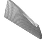
b) Second mode
c) Third mode
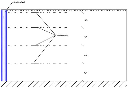
In the first mode, as shown in Fig. 3, in each half cycle of the vibration, the reinforcements and soil are under tension and in the remaining half cycle both of them are under compression. Therefor in the first half cycle, only the effect of the reinforcements and in the second half cycle, just the effect of the soil is considered in wall’s equation of motion. The reinforcements in this study are assumed to be positioned at the back of the wall at certain heights which are: (, , and ), where is wall’s height.
To consider the effect of the reinforcements at the back of the wall, reinforcement’s term must be integrated in both the x and y directions and then, be added to wall’s equation of motion:
By solving the above equation, using the mentioned method, the damped natural frequency of a reinforced retaining wall considering the soil-wall-reinforcement interactions is obtained as follows Eq. (41):
By substituting Eqs. (38) and (27) into Eq. (36), effective damped natural frequency of a reinforced retaining wall, considering differences between compression and tension in soil’s and reinforcement’s behaviors is derived.
By using the same procedure for the second and third modes, effective damped natural frequencies of a reinforced retaining wall for the second and third modes are derived. Thus, according to Figs. 3 and 4 for the second mode, it is shown that, in each half cycle of the vibration, half of the soil along the length of the wall is under compression and the remaining portion is under tension; meanwhile, when half of the soil is under compression, the same half of the reinforcements are under tension and vice versa.
To implement the aforementioned procedure throughout the Galerkin method, while integrating wall’s equation of motion, the effect of the reinforcements and soil must be integrated separately in half of the length of the wall for each half cycle. For example, in the first half cycle, the reinforcements’ effect is integrated from 0 to 0.5 and the effect of the soil is integrated from 0.5 to and for the second half cycle the remaining regions are used as integration domains. By substituting Eqs. (39) and (40) into Eq. (36), damped natural frequency of a reinforced retaining wall corresponding to the second mode is derived:
Fig. 4First mode shape function of free-free beam Rao [48]
![First mode shape function of free-free beam Rao [48]](https://static-01.extrica.com/articles/19638/19638-img6.jpg)
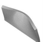
For the third mode, as shown in Figs. 3 and 5, in the first half cycle, the soil is under tension from 0.224 to 0.776 and is under compression from 0 to 0.224 and 0.776 to , while, the reinforcements are under compression in 0.224 to 0.776 and are under tension from 0 to 0.224 and 0.776 to . In the second half cycle the compressive and tensile regions illustrated earlier change to tensile and compressive regions respectively for both the soil and reinforcements. By using the procedure similar to the second mode, and for the third mode is obtained as Eqs. (41) and (42) and by substituting these equations into Eq. (36), the third mode damped natural frequency of a reinforced retaining wall considering the soil-wall-reinforcement interactions is obtained:
Fig. 5Second mode shape function of free-free beam Rao [48]
![Second mode shape function of free-free beam Rao [48]](https://static-01.extrica.com/articles/19638/19638-img7.jpg)
4. Simulation results
In this section, the obtained results from the proposed method and analytical equations are investigated. In Table 2 the comparison between two conditions which are proposed in this study is shown. The first condition is related to the case in which there is no difference between compressive and tensile behaviors of the soil and reinforcements, while the second condition is related to the case in which the difference between compressive and tensile behaviors of the soil and reinforcements is considered. As presented in Table 2, considering the different behaviors for the soil and reinforcements has a significant effect on the natural frequency of the reinforced retaining wall. In this section, the length of the wall is 20 m, the thickness of the wall is 0.5 m, the elastic modulus of the soil and reinforcements are 60 and 3000 MPa respectively. The parameters which are mentioned in Table 1 are constant in all of the calculations performed here in this study. Barden’s relation i.e. Eq. (43) is used in this study to calculate the stiffness of the springs at the back of the wall Barden [50]:
where , and are soil elastic modulus, Poisson’s ratio and thickness of the wall.
Table 1Some of the constant parameters used in this article
Wall | Reinforcement | Soil |
2.35e10 (MPa) | 0.2 | 0.3 |
0.17 (MPa) | (m2) |
The effect of reinforcement on natural frequency of retaining wall is presented in Table 3. As demonstrated, the effect of the reinforcement in the first mode is more than that of the second mode, and the reinforcement’s effect in the second mode is more than that of the third mode as well. The array of the reinforcements is shown in Fig. 6. As the number of the reinforcements increases along the height of the wall, their effects on the natural frequency of the reinforced retaining wall increases. In this section length of the wall is 20 m, thickness of the wall is 0.5 m and elastic modulus of the soil and reinforcement are 60 and 4500 MPa respectively.
Table 2The effect of different tensile and compressive behaviors of the soil and reinforcements on the natural frequency of reinforced retaining wall
No difference between compressive and tensile behaviors | |||||||
Dimensionless undamped frequency | Dimensionless damped frequency | ||||||
No damping | 8.33 | 10.42 | 12.5 | ||||
First mode | Second mode | Third mode | First mode | Second mode | Third mode | ||
4 | 8 | 9.30 | 9.36 | 9.60 | 9.20 | 9.21 | 9.39 |
6 | 12 | 8.78 | 8.80 | 8.92 | 8.67 | 8.64 | 8.70 |
8 | 16 | 8.66 | 8.67 | 8.75 | 8.55 | 8.51 | 8.52 |
Different compressive and tensile behaviors | |||||||
Dimensionless undamped frequency | Dimensionless damped frequency | ||||||
No damping | 8.33 | 10.42 | 12.5 | ||||
First mode | Second mode | Third mode | First mode | Second mode | Third mode | ||
4 | 8 | 5.31 | 5.32 | 7.35 | 5.05 | 5.06 | 7.07 |
6 | 12 | 3.45 | 4.26 | 6.47 | 2.83 | 3.92 | 6.16 |
8 | 16 | 2.72 | 3.99 | 6.25 | 2.16 | 3.63 | 5.92 |
Table 3Effect of the reinforcements on natural frequency of reinforced retaining walls
Without reinforcements | |||||||
Dimensionless undamped frequency | Dimensionless damped frequency | ||||||
No damping | 8.33 | 10.42 | 12.5 | ||||
First mode | Second mode | Third mode | First mode | Second mode | Third mode | ||
4 | 8 | 4.72 | 5.08 | 7.25 | 4.38 | 4.80 | 6.97 |
6 | 12 | 2.43 | 4.07 | 6.39 | 0.94 | 3.71 | 6.07 |
8 | 16 | 1.46 | 3.85 | 6.19 | 0.71 | 3.47 | 5.86 |
By reinforcements | |||||||
Dimensionless undamped frequency | Dimensionless damped frequency | ||||||
No damping | 8.33 | 10.42 | 12.5 | ||||
First mode | Second mode | Third mode | First mode | Second mode | Third mode | ||
4 | 8 | 5.40 | 5.42 | 7.40 | 5.13 | 5.16 | 7.13 |
6 | 12 | 3.80 | 4.35 | 6.51 | 3.30 | 4.02 | 6.22 |
8 | 16 | 3.10 | 4.07 | 6.28 | 2.33 | 3.71 | 6.01 |
Fig. 6The array of reinforcement
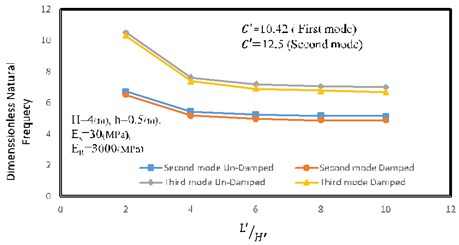
It appears from Fig. 7 that length to height ratio has significant effect on natural frequency of the wall especially on second and third mode. One of the most important characteristics of 3D analysis is considering the activated mode in the length of the wall which is not considered in 2D analysis. As shown, by increasing the length of the wall, it becomes more flexible and natural frequency decreases. As shown in Fig. 7, when the length to height ratio gets higher than 5, increasing the length of the wall has a slight effect on the second and third mode natural frequency of reinforced retaining walls. In this section, the first mode is not considered because the length of the wall has no effect on natural frequency of a reinforced retaining wall. Elastic modulus of the soil and reinforcement are 30 and 3000 MPa respectively, height of the wall is 4 m and thickness of the wall is 0.5 m.
Fig. 7Length to height ratio versus dimensionless frequency
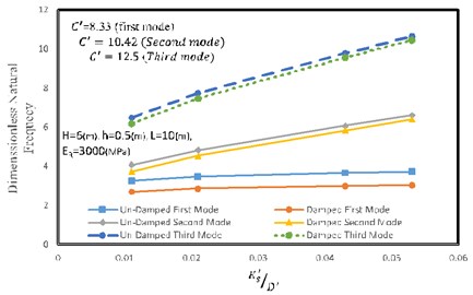
As evident from Fig. 8, dimensionless frequency of reinforced retaining wall is highly affected by the soil stiffness to wall rigidity ratio (that is known as stiffness ratio in this article). By increasing the stiffness ratio, natural frequency of the reinforced retaining wall is also increased. Since the second and third modes are activated along the length of the wall, increasing the stiffness of the soil, affects the third and second modes more than the first mode. In this section, the length of the wall is 10 m, height of the wall is 6 m, thickness of the wall is 0.5 m and elastic modulus of the reinforcement is 3000 MPa.
Fig. 8Effect of the stiffness ratio on natural frequency of the reinforced retaining wall
The effect of the reinforcement’s stiffness to wall rigidity ratio on the natural frequency of the reinforced retaining wall is depicted in Fig. 9. In general, by increasing the stiffness of the reinforcement versus wall rigidity, natural frequency of the retaining wall is increased. As shown in Fig. 9, the effect of increasing the reinforcement stiffness on higher modes, such as the third mode, is less than that is on the lower modes. In this section, the wall is 6 meters high, 10 meters long, 0.5 meter thick and has elastic modulus of 30 MPa.
Table 4 presents the effect of damping coefficient on dimensionless damped natural frequency of the reinforced retaining wall. According to the results obtained, increasing the damping coefficient, causes the damped natural frequency of the retaining wall to reduce. In each mode when the damping coefficient gets a value more than a specified magnitude (i.e. critical damping coefficient) the whole system becomes over damped and the damped natural frequency becomes zero. The results showed that critical damping value has an order as the mode number increases. Critical damping for each mode is related to physical characteristic of model especially stiffness. In this section length of the wall is 10 m, height of the wall is 6, thickness of the wall is 0.5 m, elastic modulus of the soil is 60 MPa and elastic modulus of the reinforcement is 3000 MPa.
Fig. 9Effect of reinforcement stiffness to the wall rigidity ratio on natural frequency of the reinforced retaining wall
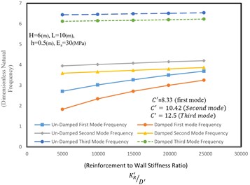
Table 4Effect of damping on damped natural frequency of reinforced retaining wall
(Dimensionless damping) | Dimensionless natural frequency | ||
First mode | Second mode | Third mode | |
0 | 3.44 | 4.84 | 7.74 |
4.17 | 3.31 | 4.8 | 7.71 |
8.33 | 2.83 | 4.65 | 7.58 |
12.50 | 1.51 | 4.41 | 7.48 |
16.67 | 0 | 4.05 | 7.28 |
20.83 | 0 | 3.52 | 6.99 |
25.00 | 0 | 2.75 | 6.63 |
29.17 | 0 | 1.36 | 6.18 |
33.33 | 0 | 0 | 6.61 |
37.5 | 0 | 0 | 4.88 |
41.67 | 0 | 0 | 3.86 |
45.83 | 0 | 0 | 1.86 |
50.00 | 0 | 0 | 0 |
5. Comparison of the results with those of the other researchers and finite element method (FEM)
In this section, the obtained results are compared with those of finite element method to verify the proposed method. Thus, Abaqus software is used to model the retaining wall, reinforcements and soil. Solid section is used for modeling the wall while spring and damper elements are used to model the reinforcements, soil and system damping. The obtained results are compared with finite element method in Table 5.
In this section, the wall is 20 meters long, 0.5 meter thick while the elastic modulus of the soil and the reinforcements are 60 and 3000 MPa respectively.
In the following, the results obtained using the proposed method and the results from the full scaled experiment performed by Elgamal et al. [20] are compared to verify the proposed method. Elgamal et al. [20] studied the forced vibration of a wall with varying height experimentally to investigate the frequencies of a retaining wall in the 3D domain. Finally, by using the finite element modeling, they studied the behavior of a wall with fixed and varying height. The obtained frequencies are presented in Table 6 considering a wall 9 meters high, 0.4 meter thick and 45 meters long. The backfill had a thickness of 36.6 meters, Poisson’s ratio of 0.48 and elastic coefficient of 30. The wall has a Poisson’s ratio of 0.15, elastic modulus of 19 GPa and density of 2300 kg/m3 similar to Elgamal et al. (1996). Considering the fact that the results of Elgamal et al. [20] were presented for the first two modes which were activated along the height of the wall, thus in the proposed method the second mode shape function acting in the height of the wall is used.
The damping coefficient is assumed to be 5 % here in this study as it was in Elagamal et al. [20].
Table 5Comparison of the obtained results with those of finite element
First mode | ||||
(Proposed method) | (FEM) | Relative error (%) | ||
8 | 26.12 | 25.97 | 2.33 | 0 |
8 | 25.26 | 24.31 | 3.76 | 8.33 |
12 | 17.22 | 16.93 | 1.68 | 0 |
12 | 14.14 | 13.069 | 7.57 | 8.33 |
16 | 13.57 | 13.46 | 0.81 | 0 |
16 | 8.33 | 7 | 15.97 | 8.33 |
Second mode | ||||
(Proposed method) | (FEM) | Relative error (%) | ||
8 | 26.34 | 33.09 | –25.63 | 0 |
8 | 25.42 | 31.56 | –28.24 | 10.42 |
12 | 21.27 | 19.46 | 8.51 | 0 |
12 | 18.81 | 17.22 | 8.45 | 10.42 |
16 | 19.96 | 16.11 | 19.29 | 0 |
16 | 17.32 | 13.45 | 22.34 | 10.42 |
Third mode | ||||
(Proposed method) | (FEM) | Relative error (%) | ||
8 | 36.78 | 43.28 | –17.67 | 0 |
8 | 35.38 | 41.8 | –18.15 | 12.5 |
12 | 32.36 | 36.61 | –13.13 | 0 |
12 | 30.78 | 34.91 | –13.42 | 12.5 |
16 | 31.24 | 28.85 | 7.65 | 0 |
16 | 29.6 | 26.81 | 9.43 | 12.2 |
Table 6Comparison of the results of the proposed method with field data obtained by Elgamal et al. [20]
Mode number | Damped natural frequency | Damping ratio | |
Elgamal et al. [11] | Proposed method | ||
1 | 6.3 | 4.4 | 5 % |
2 | 17.5 | 15.3 | 5 % |
6. Conclusions
This paper aimed to obtain an accurate formulation to estimate the effect of damping on the first three damped natural frequencies of flexible retaining walls having fixed cross section based on the theory of plates on an visco-elastic foundation by invoking the Galerkin method in the 3D domain. The tensile and compressive behaviors of the backfill and reinforcements were also separated from each other in an analytical expression and the results were compared with those of having backfill and reinforcements behaving completely under tension and compression.
Major findings from this study can be summarized as follows:
1) In contrast to previous studies, the fundamental damped natural frequencies of the active modes existing in length of the wall are investigated using the three-dimensional modeling. Finally, new analytical expressions for calculating the first three fundamental damped natural frequencies of the retaining wall are presented. The expressions are obtained in three dimensions for different length to height ratios.
2) The main purpose of this paper is to inspect the effect of damping on natural frequency of a reinforced retaining wall and also rectify the weaknesses of the two dimensional analysis carried out for obtaining the free vibration frequency of a retaining wall as well. Specially the modes which appear along the length of the wall. These modes affect the dynamic behavior considerably and in this paper these modes are analyzed more precisely using an analytical and simplified expressions, presented in this study, considering the interactions between the wall and backfill and reinforcements.
3) In this paper, a stiffness ratio parameter is also defined and it is shown that increasing this ratio causes the soil-wall system to become stiffer and increases the frequency. As we know the earthquake is low frequency and by using the stiffer wall and soil (stiffness ratio) we can remove the natural frequency of the wall from earthquake frequency.
4) According to these findings of the study, the length to height ratio has a significant effect on natural frequency until length to height ratio of 5, but for the length to height ratio more than 5, increasing the length of the wall has a slight effect on natural frequency of the second and third mode of the wall.
5) Comparing the results of the proposed method with the results presented by other researchers, specially, Elgamal et al. (1996), which was obtained using experimental and numerical modeling, showed that the proposed method has an acceptable accuracy especially due to the consideration of different tensile and compressive behaviors of the reinforcements and soil respectively.
6) Separating the tensile and compressive behaviors of the soil and reinforcements can considerably affect the fundamental frequency of the wall. As the results showed, increasing the height of the wall increases the effect of separating the tensile and compressive behaviors of the backfill and reinforcements on fundamental frequency of the wall up to 65 %.
7) It should be noted that none of the previous studies have analyzed the wall free vibration in three dimensions neither analytically nor numerically. According to this fact the longitudinal vibration modes were ignored in previous studies while they are considered and investigated here in this paper. According to these finding engineers must use length mode instead height modes in second and third mode for analyzing and designing the wall.
8) In this study, according to the obtained results, increasing the damping coefficient to a value more than a certain amount (i.e. critical damping coefficient), which is relative to the stiffness of the system, causes the system to become over-damped. The proposed method can show that procedure very well. In new construction techniques engineers can use damper element for increasing the damping until frequency become below the earthquake frequency to escaping from the earthquake danger.
References
-
Koseki J., et al. Seismic stability of reinforced soil walls. Proceedings of 8th International Conference on Geosynthetics, Yokohama, Vol. 1, 2006.
-
Tatsuka F., Koseki J., Tateyama M. Performance of reinforced soil structures during the 1995 Hyogo-Ken Nambu earthquake. Special Lecture. Proceedings of the International Symposium on Earth Reinforcement, Balkema, Rotterdam, The Netherlands, Vol. 2, 1997, p. 973-1008.
-
Tatsuoka Fumio, Masaru Tateyama, Masayuki Koda Ken-ichi Kojima, Toyoji Yonezawa, Yoshinori Shindo, Shin-ichi Tamai Research and construction of geosynthetic-reinforced soil integral bridges. Transportation Geotechnics, Vol. 8, 2016, p. 4-25.
-
Huang C. C., Wang W. C. Seismic displacement of a geosynthetic-reinforced wall in the 1995 Hyogo-Ken Nambu earthquake. Soils and Foundations, Vol. 45, Issue 5, 2005, p. 1-10.
-
Chopra Anil K. Dynamics of Structures. Prentice Hall, New Jersey, 2001.
-
Shodja H. M., Ahmadi S. F., Eskandari M. Boussinesq indentation of a transversely isotropic half-space reinforced by a buried inextensible membrane. Applied Mathematical Modelling, Vol. 38, Issue 7, 2014, p. 2163-2172.
-
Selvadurai A. P. S. Boussinesq indentation of an isotropic elastic halfspace reinforced with an inextensible membrane. International Journal of Engineering Science, Vol. 47, Issue 11, 2009, p. 1339-1345.
-
Ahmadi S. F., Eskandari M. Axisymmetric circular indentation of a half-space reinforced by a buried elastic thin film. Mathematics and Mechanics of Solids, Vol. 19, Issue 6, 2014, p. 703-712.
-
Ahmadi S. F., Parham S., Eskandari M. Axisymmetric response of a bi-material full-space reinforced by an interfacial thin film. International Journal of Solids and Structures, Vol. 90, 2016, p. 251-260.
-
Selvadurai A. P. S. The displacement of a rigid circular foundation anchored to an isotropic elastic half-space. Geotechnique, Vol. 29, Issue 2, 1979, p. 195-202.
-
Eskandari M., Ahmadi S. F., Khazaeli S. Dynamic analysis of a rigid circular foundation on a transversely isotropic half-space under a buried inclined time-harmonic load. Soil Dynamics and Earthquake Engineering, Vol. 63, 2014, p. 184-192.
-
Ahmadi S. F., Eskandari M. Vibration analysis of a rigid circular disk embedded in a transversely isotropic solid. Journal of Engineering Mechanics, Vol. 140, Issue 7, 2013, p. 04014048.
-
Chati M., Rand R., Mukherjee S. Modal analysis of a cracked beam. Journal of Sound and Vibration, Vol. 207, Issue 2, 1997, p. 249-270.
-
Matsuo H., Ohara S. Lateral earth pressure and stability of quay walls during earthquakes. Proceedings of the 2nd World Conference on Earthquake Engineering, Tokyo-Kyoto, Japan, 1960.
-
Wood J. H. Earthquake-Induced Soil Pressures on Structures, Ph.D. Dissertation, California Institute of Technology, Pasadena, 1973.
-
Scott R. F. Earthquake-induced earth pressures on retaining walls. Proceedings of the 5th World Conference on Earthquake Engineering, Rome, Italy, 1973.
-
Wu G. Dynamic Soil-Structure Interaction: Pile Foundations and Retaining Structures. University of British Columbia, Vancouver, 1994.
-
Yeh C. S. Dynamic response of retaining walls during earthquake, Proceedings of the International Symposium on Earthquake Structural Engineering, St. Louis, USA, 1976, p. 387-392.
-
Jain S. K., Scott R. F. Seismic analysis of cantilever retaining walls. Transactions of the 10th International Conference on Structural Mechanics in Reactor Technology, Anaheim, USA, 1989, p. 241-246.
-
Elgamal Ahmed-W., Sreenivas Alampalli, Paul Van Laak Forced vibration of full-scale wall-backfill system. Journal of Geotechnical Engineering, Vol. 122, Issue 10, 1996, p. 849-858.
-
Ewins D. J. Modal Testing: Theory and Practice. John Wiley and Sons, Inc., New York, N.Y., 1984.
-
Bathurst R. J., Hatami K. Seismic response analysis of a geosynthetic reinforced soil retaining wall. Journal of Geosynthetic International, Vol. 5, Issues 1-2, 1998, p. 127-166.
-
Hatami K., Bathurst R. J. Effect of structural design on fundamental frequency of reinforced soil retaining walls. Journal of Soil Dynamics and Earthquake Engineering, Vol. 19, Issue 3, 2000, p. 137-157.
-
El-Emam M. M., Bathurst R. J. Influence of reinforcement parameters on the seismic response of reduced-scale reinforced soil retaining walls. Journal of Geotextile Geomembrane, Vol. 25, Issue 1, 2007, p. 33-49.
-
Zarnani S., El-Emam M. M., Bathurst R. J. Comparison of numerical and analytical solutions for reinforced soil wall shaking table test. Geomechanics and Engineering, Vol. 3, 2011, p. 291-321.
-
Ehrilch M., Mirmoradi S. H. Evaluation of the effects of facing stiffness and toe resistance on the behavior of GRS walls. Journal of Geotextile Geomembrane, Vol. 40, 2013, p. 28-36.
-
Wang L., Chen G., Chen S. Experimental study on seismic response of geogrid reinforced rigid retaining walls with saturated backfill sand. Journal of Geotextiles and Geomembranes, Vol. 43, Issue 1, 2015, p. 35-45.
-
Balakrishnan S., Viswanadham B. V. S. Performance evaluation of geogrid reinforced soil walls with marginal backfills through centrifuge model tests. Journal of Geotextile and Geomembrane, Vol. 44, Issue 1, 2016, p. 95-108.
-
Yazdani H., Hatami K., Grady B. P. Sensor-enabled geogrids for performance monitoring of reinforced soil structures. ASTM Journal of Testing and Evaluation, Vol. 44, Issue 1, 2016, p. 391-401.
-
Ling H. I., Yang S., Leshchinsky D., Liu H., Burke C. Finite-element simulations of full-scale modular-block reinforced soil retaining walls under earthquake loading. Journal of Engineering Mechanics, Vol. 136, 2010, p. 653-661.
-
Bathurst R. J., Hatami K. Review of numerical modeling of geosynthetic reinforced soil walls. 10th International Conference of the International Association for Computer Methods and Advances in Geomechanics, Vol. 2, 2001, p. 1223-1232.
-
Hatami K., Bathurst R. J. Numerical model for reinforced soil segmental walls under surcharge loading. Journal of Geotechnical and Geoenvironmental Engineering, Vol. 132, 2006, p. 673-684.
-
Selvadurai A. P. S. Mindlin’s problem for a half space with a bonded flexural surface constraint. Mechanics Research Communications, Vol. 28, Issue 2, 2001, p. 157-164.
-
Selvadurai A. P. S., Willner K. Surface-stiffened elastic half space under the action of a horizontally directed Mindlin force. International Journal of Mechanical Sciences, Vol. 48, Issue 10, 2006, p. 1072-1079.
-
Eskandari M., Ahmadi S. F. Green’s functions of a surface-stiffened transversely isotropic half-space. International Journal of Solids and Structures, Vol. 49, Issue 23, 2012, p. 3282-3290.
-
Ghanbari A., Hoomaan E., Mojallal M. An analytycal method for calculating the natural frequency of retaining walls. International Journal of Civil Engineering, Vol. 1, 2013, p. 1-9.
-
Abbasi O., Ghanbari A., Hosseini S. A. A. An analytical method for calculating the natural frequency of reinforced retaining walls with soil structure interaction effect. Journal of Geosynthetics International, Vol. 21, Issue 1, 2014, p. 53-61.
-
Ramezani M. S., Ghanbari A., Hosseini S. A. A. Analytical method for calculating natural frequencies of geosynthetic-reinforced wall with full-height concrete facing. Journal of Geosynthetics International, 2016, p. 1-13.
-
Darvishpour A., Ghanbari A., Hosseini S. A. A., Nekooei M. New analytical approach for determining 3D natural frequency of retaining walls. International Journal of Civil Engineering, Vol. 15, Issue 3, 2017.
-
Li X., Aguilar O. Elastic earth pressures on rigid walls under earthquake loading. Journal of Earthquake Engineering, Vol. 4, 2000, p. 415-435.
-
Gazetas G., Psarropoulos P. N., Anastasopoulos I., Gerolymos N. Seismic behavior of flexible retaining systems subjected to short-duration moderately strong excitation. Soil Dynamics and Earthquake Engineering, Vol. 24, Issue 7, 2004, p. 537-550.
-
Lanzoni L., Radi E., Tralli A. On the seismic response of a flexible wall retaining a viscous poroelastic soil. Soil Dynamics and Earthquake Engineering, Vol. 27, Issue 9, 2007, p. 818-842.
-
Tang Y., Yeh C.-S. A note on the seismic response of rigid cantilever retaining walls. Nuclear Engineering and Design, Vol. 241, 2011, p. 693-699.
-
Mojallal M., Ghanbari A. Prediction of seismic displacements in gravity retaining walls based on limit analysis approach. Journal of Structural Engineering and Mechanics, Vol. 42, Issue 2, 2012.
-
Chen J. F., Tolooiyan A., Xue J. F., Shi Z. M. Performance of a geogrid reinforced soil wall on PVD drained multilayer soft soils. Journal of Geotextiles and Geomembranes, Vol. 44, Issue 3, 2016, p. 219-229.
-
Liu H., Wang X., Song E. Long-term behavior of GRS retaining walls with marginal backfill soils. Journal of Geotextiles and Geomembranes, Vol. 27, Issue 4, 2009, p. 295-307.
-
Shi Dongyan, Anees Ur Rehman Analytical approaches to vibration analysis of circular, annular and sectorial plates subjected to classical and arbitrary boundary conditions-a literature survey. Journal of Vibroengineering, Vol. 18, Issue 2, 2016, p. 731-743.
-
Rao S. S. Vibration of Continuous Systems. John Wiley and Sons, New Jersey, NJ, USA, 2007.
-
Leissa A. W. Vibration of Plates. DTIC Document, 1969.
-
Barden L. The Winkler model and its application to soil. Journal of Structure Engineering, Vol. 41, 1963, p. 279-280.
About this article

Ali Ghanbari was Geotechnical consultant. The Free vibration of reinforced retaining wall and dynamic analyses of reinforced retaining wall and the soil-structure modeling theory was under his supervision. Seyyed Ali Asghar Hosseini was mechanical consultant in plate vibration theory, dynamic behavior of plates in transverse vibration and modal analysis of plates. Masoud Nekooei was consultant in dynamic structural analysis and approximate analytical approach certainly in using Galerkin method in plate vibration theory. Tyebbeh Darvishpour implemented finite element modeling.
