Abstract
With the wide use and longer life cycle of tower crane, the risk of coming across earthquake during service period increases. Hence, the seismic responses and dynamic characteristics of tower crane are becoming more important. In this paper, seismic responses and dynamic characteristics of boom tower crane were analyzed basing on measured strong earthquake excitation. The finite-element models of boom tower crane were established on Ansys platform. Key locations of max stress with different working conditions were confirmed. The stress and displacement of key nodes were compared and analyzed in time-history response with measured earthquake excitation. It was found that the sensitivities of different modes to the change of jib angle were distinct. Meanwhile the change of jib had a greater effect on dynamic characteristics of tower crane than the change of required lift capacity. When the jib was in small angle, numerical results showed that the lifting heavy object could be regarded as inertial damper, which absorbed earthquake energy and reduced displacement of tower crane partly. The results are of practical significance for seismic design and the layout of stability monitoring stations in tower crane.
1. Introduction
Tower crane are widely used in the construction of high-rise buildings. Due to its relatively severe environmental condition, the analysis of the dynamic characteristics is significant for both the design and operation of tower cranes. Nevertheless, the seismic behavior of tower crane has not been paid enough attention in the construction process [1]. It is believed that the construction process belongs to the transient design condition, and the earthquake is a small probability event, which is less likely to be applied to the tower crane. Therefore, the seismic design of tower crane is often neglected.
According to statistical data, there are more than 500 earthquakes above Ms3.0 in China in 2017. In Wenchuan earthquake, many tower cranes were damaged or even collapsed in construction site, causing great economic losses. Five tower cranes collapsed, and the others were broken off or had large bending deformation in different parts. More than one hundred tower cranes were damaged in different degrees in Xi’an city, China [2]. In Japan, many port cranes and tower cranes had been damaged in the earthquake, which brought great economic losses [3]. At present, tower cranes are less resistant to earthquakes during the construction. Once an earthquake occurs, it will lead to serious consequences [1-4]. In conclusion, the probability of coming across earthquake increases with the universality and longer life cycle of tower crane [5]. It is necessary to analyze the seismic responses and dynamic characteristics of tower crane.
A small number of scholars have paid attention to researches on seismic response of tower cranes. Xie R. [2] discussed the main damage forms, the dynamic characteristics and the reasons for the damage of tower cranes according to the damage situation of tower crane in Xi’an city during the Wenchuan earthquake. Eihab M. A. [3] presented that the control strategies should be designed to take into account including stationary and transient responses. Li Y. L. [6] analyzed the reasons of damaged tower cranes in earthquake, and the importance of dynamic response analysis for tower cranes was represented. Basing on tower cranes attached to the high-rise building, effect of different TMD schemes on dynamic characteristics with the earthquake excitation were summarized by Shen T. [7]. Feng J. [8] found cable passages had significant effect on both static tensions and dynamic properties of tower cranes. The proposed super element model in the paper provided more accurate and realistic results in dynamic analyses of the crane system. Hazriq I. J. [9] derived the dynamic model using Lagrange equation, and pointed out that cable length, payload mass and trolley mass can affect the performances of the gantry crane system. Huang L. J. [10] built up a typical tower crane frame numerical model with SAP2000, and found that the maximal displacements might be large to over 1.0 m. The associated maximal velocity and acceleration can be greater than 4.0 m/s and 40.0 m/s2, respectively at the highest position of tower crane. Hence it is essential to be focused. He Y. H. [11] analyzed vibration frequency of the tower cranes system before and after the earthquake spectrum and discussed max stress location of the tower crane in practical working condition. Abuduwalisi [12] found the difference of spatial coherency in different types of sites (bedrock, normal site and soft soil). The spatial coherency of soft soil site had the fastest attenuation, the normal site and the bedrock site had the slowest attenuation speed. The coherence function value was still noteworthy between two points with 20.0 km distance and coherency of horizontal ground motions was more significant than that of vertical ground motions. Tower crane seismic responses in consideration of building-crane interaction were studied with different heights [13]. Some researchers studied the active vibration control method of tower crane [14], field applicability of the rotation-controllable tower crane [15], optimum of tower crane selection [16], effect of wind load on the tower crane [17]. From these researches, it can be summarized that seismic response of tower crane under different working conditions have not been paid enough attention.
There are three kinds of tower cranes mainly used in construction, including gantry tower crane, rotary tower crane and boom tower crane. The capacity of the boom to bear loads in compression offers boom tower cranes a structural advantage over other types of crane, which makes it more popular in construction. Therefore, this paper introduced seismic responses and dynamic characteristics of boom tower crane basing on measured strong earthquake excitation. ZSL1250 boom tower crane was taken as the analysis object and some finite-element models were established on Ansys platform. Three kinds of typical working condition with two records of observed earthquake wave were considered. The purpose of the present study is to gain further understanding of damage forms and dynamic characteristics of boom tower crane under one-dimensional and three-dimensional seismic excitation by numerical method.
2. Background
Yunnan province of China is located in the margin zone of the eastern part of the Eurasian seismic belt, where the crustal movement is strong, and the earthquakes occur frequently. On average, there are earthquakes above Ms5.0 three times each year, and earthquakes of Ms6.0-6.9 at least once every two years, even an earthquake of above Ms7.0 every eight years. Yunnan province accounts for only 4.0 % of the country’s land area, while the total energy released by earthquake accounts for 23.0 % of the whole country. There have been five strong earthquakes hitting the surrounding cities around Kunming since 2010, of which two of them have reached over Ms6.0 (Pu’er Valley earthquake of Ms6.6 and Ludian earthquake of Ms6.5). This paper selected Wanda Plaza project in Xishan district, Kunming, Yunnan province as the practical engineering background, by taking ZSL1250 boom tower crane as research object. The luffing system of jib, as a main characteristic of the boom tower crane, can make full use of effective height of the boom. In the construction of subtraction, boom tower crane is embedded in the ground for operation. With the increase of construction height, boom tower crane begins to climb outside a building. The paper presented numerical modelling and structural dynamic analysis of boom tower crane applied in construction engineering.
3. Finite-element modelling
3.1. Element types and material properties
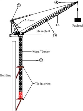
Boom tower crane is mainly comprised of boom, cab, A-frame, balance arm with counterweight, mast, trolley mechanism, slewing mechanism and hoisting mechanism, etc. According to the structural characteristics of tower crane, mast sections, boom, A-frame, the balance arm were modelled by Beam188 element. Slewing mechanism was simulated by Shell63 element. Counterweight of balance arm, cab, electric machinery and hook of trolley or hoisting mechanism were simplified to be lumped-mass and Mass21 element was used. The luffing and hoist cables were considered as pure tensile members, which can be modelled with Link180 element. The main unit parameters of boom and mast were shown in Table 1.
Table 1Material properties and main unit parameters of mast and boom
Steel | Yield stress | Density | Poisson ratio | Elastic modulus |
Q345B | 345 MPa | 7800 kg/m3 | 0.3 | 206 GPa |
Structural member | Material | Geometric parameter | Element selection | |
Standard mast sections | Steel truss | 3.2×3.2×4 m | Beam188 | |
Main chords of mast section | H-beam | H400×400 mm | Beam188 | |
Web members of mast section | Angle steel | L160×160×16 mm | Beam188 | |
Top chords of boom | Tube steel | Ø133×10 mm | Beam188 | |
Bottom chords bar of boom | Tube steel | Ø127×8 mm | Beam188 | |
Web members of boom | Tube steel | Ø70×4 mm | Link180 | |
3.2. Basic assumptions
In order to provide an accurate and realistic result in dynamic analyses of crane system, this paper adopted simplified finite-element models. The final model quality, which was equivalent to the real tower crane, was determined by adjusting the density and elastic modulus of element. The connection between mast sections including ear-plate joint, pins and bolts were not considered in the model, and were regarded as rigid connections simply.
The mast of tower crane could be braced at various elevations of the inner concrete core with tie-in struts. The models of tower crane were analyzed separately without considering the building-crane interaction. The type, level, direction and position of load applied on tower crane model were defined in accordance with the real load of an actual tower crane when operating. Meanwhile, all the stresses and strains of the structural members were in linear elastic range and Hookes law was applied.
4. Dynamic characteristics analysis
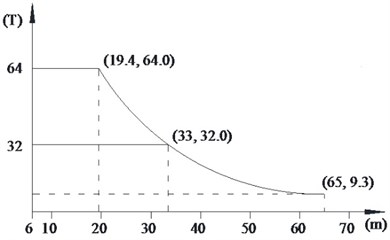
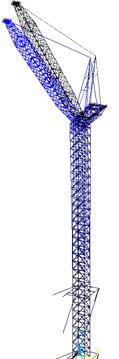
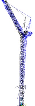
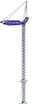
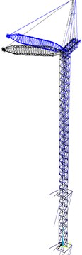
Three kinds of typical fully loaded working conditions were selected to investigate the dynamic characteristics of boom tower crane, as shown in Table 2. Lifting capacity is described according to the payload curve of tower crane, as shown in Fig. 1. It is the maximum allowed payload in correspondence with the rotation radius of boom under different working conditions. Changes in the hoisting speed was negligible in this paper. The payload was assumed to be picked up or lowered down at a constant speed in loading duration.
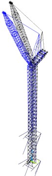
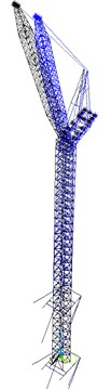
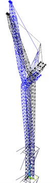
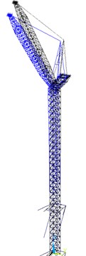
Finite-element models under three working conditions were shown in Fig. 2. The -direction was the projection direction of the boom in horizontal plane, and -direction was the vertical direction along tower-body. The y-direction was the vertical direction of - plane or the lifting plane. The numerical models comprised of 3761 elements, 7887 nodes and were fixed through tie-in struts.
The compelled vibration characteristics of tower crane are close related to the natural frequencies and vibration modes. Hence, it is necessary to conduct modal analysis to obtain the main modal frequencies and corresponding vibration modes of boom tower crane.
Table 2Parameters of tower crane under different working conditions
Working condition | Rotation radius of jib (m) | Jib angle (°) | Payload () |
One | 19.4 | 68 | 64 |
Two | 33 | 51 | 32 |
Three | 50 | 20 | 18.1 |
Fig. 1The payload curve of boom tower crane
4.1. Dynamic characteristics results
The subspace iteration method was applied to analyse the structural modal characteristics. First five natural frequencies and mode shapes of tower crane under different working conditions were obtained, as shown in Table 3, which included the deformation characteristics of corresponding modes. Furthermore, five kinds of vibration patterns were labelled with Type-A to Type-E, according to deformation characteristics respectively. Because the first few modes are usually important in structural dynamics, Fig. 3-Fig. 5 showed the vibration-distortion of the first, third and fifth mode of crane models. Fig. 6 showed the changes of natural frequencies of tower crane at different jib angles.
Fig. 2Finite-element models of boom tower crane: a) working condition one, b) working condition two, c) working condition three
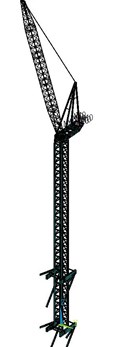
a) WC-1
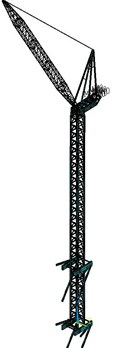
b) WC-2
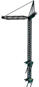
c) WC-3
Fig. 3Vibration pattern of working condition one (WC-1): a) first mode, b) third mode, c) fifth mode
a)
b)
c)
Fig. 4Vibration pattern of working condition two (WC-2): a) first mode, b) third mode, c) fifth mode
a)
b)
c)
Fig. 5Vibration pattern of working condition three (WC-3): a) first mode, b) third mode, c) fifth mode
a)
b)
c)
Fig. 6Effect of jib angles on natural frequencies of mode types
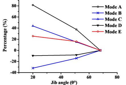
Table 3First five natural frequencies and vibration modes
Working condition | Mode | Natural frequencies (Hz) | Vibration modes | Type |
WC-1 | 1 | 0.173 | The cantilever deformation of mast | A |
2 | 0.435 | The swing side to side of jib | B | |
3 | 0.761 | Forward and backward movement of mast top | C | |
4 | 0.803 | The twisting and sway of the mast | D | |
5 | 1.873 | The twist-dominated deformation of jib | E | |
WC-2 | 1 | 0.238 | The cantilever deformation of mast | A |
2 | 0.373 | The swing side to side of jib | B | |
3 | 0.736 | The twisting and sway of the mast | D | |
4 | 0.874 | Forward and backward movement of mast top | C | |
5 | 2.171 | The twist-dominated deformation of jib | E | |
WC-3 | 1 | 0.296 | The swing side to side of jib | B |
2 | 0.314 | The cantilever deformation of mast | A | |
3 | 0.725 | The twisting and sway of the mast | D | |
4 | 1.094 | Forward and backward movement of mast top | C | |
5 | 2.353 | The twist-dominated deformation of jib | E |
As can be seen from above, it was found that:
(1) Table 3 showed that the change of jib angle had different effects on the natural frequencies. With the decreasing jib angle from WC-1 to WC-3, the natural frequencies of the first, fourth and fifth mode increased. But the second mode decreased and the third mode changes little.
(2) The overall deformation characteristics of the first five vibration modes under different working conditions were basically identical. And the corresponding modal orders changed, in addition to the fifth vibration mode that remains unchanged.
(3) Fig. 6 showed that some mode types were insensitive to the change of jib angle, while others change significantly depending on the mode shapes. For example, the Type-E mode was actually related to complex coupled boom deformations and less dependent on the jib angle, as in Figs. 3(c)-5(c).
(4) The main vibration modes of crane model were mainly characterized by the vibration of boom and coupled structural deformations of the mast, such as cantilever deformation, twisting or sway in Fig. 3-Fig. 5. From WC-1 to WC-3 with jib angle decreasing, the modal order of Type-A and Type-B vibration modes exchanged with each other, which indicated that Type-B vibration mode replaced Type-A as the dominant vibration pattern gradually. The natural frequency of Type-A vibration mode increased while Type-B vibration mode decreased. It is indicated that the stiffness of mast resisting to sway becomes larger, while the stiffness of boom resisting to swing becomes smaller. A broken boom occurred more easily than tower crane overturning.
4.2. Measurement of dynamic characteristics
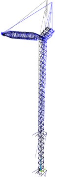
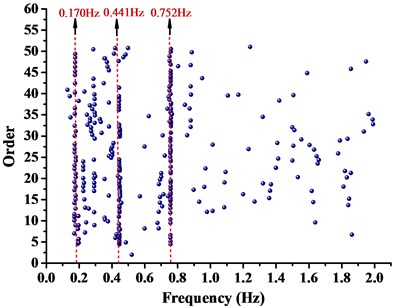
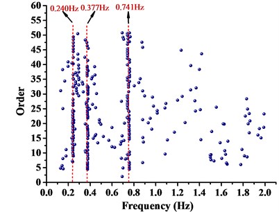
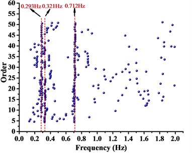
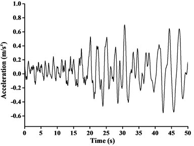
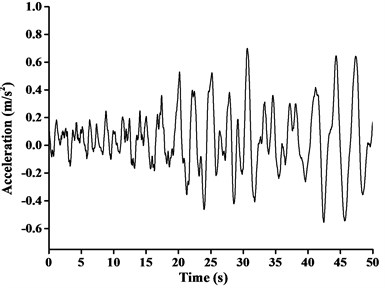
Environment random vibration stimulating method was applied to test structural dynamic characteristics, and acceleration transducer of ICP type was used to carry out data measurement. Based on engineering experience and numerical simulation, the sampling frequency was 100.0 Hz and sampling instant was 16.0 min. According to theoretical analysis and site construction condition, acceleration transducer should be arranged in location with large structural response. ZSL1250 boom tower crane and location of acceleration transducer was shown in Fig. 7. The directions of the acceleration transducer were consistent with the finite-element models of boom tower crane. Acceleration transducers were respectively arranged on the top of A-frame, in the jib head and in the middle of tower and jib. SSI method was chosen to distinguish low-end natural vibration frequencies of boom tower crane and analysis results are shown in Fig. 8.
Fig. 7ZSL1250 Boom tower crane and location of sensors
From Fig. 8, it can be seen that natural vibration frequencies of boom tower crane were distinct and accurate. The first three natural vibration frequencies of WC-1, WC-2 and WC-3 were demonstrated and compared in Table 4. It indicated that the dynamic properties of the first steps by theory essentially agreed with that by practical test. Finite-element models were established with high accuracy. Therefore, the analysis method was applicable, and the results were convincible.
Table 4Comparison of measured and calculated results
Working condition | Mode | Natural frequencies (Hz) | Deviation (%) | |
Calculated | Measured | |||
WC-1 | 1 | 0.173 | 0.170 | 1.734 |
2 | 0.435 | 0.441 | –1.379 | |
3 | 0.761 | 0.752 | 1.183 | |
WC-2 | 1 | 0.238 | 0.240 | –0.840 |
2 | 0.373 | 0.377 | –1.072 | |
3 | 0.736 | 0.741 | –0.679 | |
WC-3 | 1 | 0.296 | 0.293 | 1.014 |
2 | 0.314 | 0.321 | –2.229 | |
3 | 0.725 | 0.712 | 1.793 | |
Fig. 8Modal identification with SSI: a) working condition one, b) working condition two, c) working condition three
a) WC-1
b) WC-2
c) WC-3
5. Seismic wave parameters
5.1. Ludian seismic wave
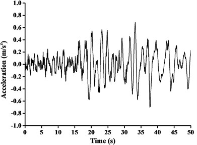
In this paper, construction site of boom tower crane was situated in Kunming, Yunnan province of China. Consequently, Ludian Ms6.5 earthquake acceleration record, which was the measured strongest and nearest ground motion record, was considered to be three-direction uniform seismic excitation. The peak ground acceleration of -direction, -direction and -direction of Ludian earthquake ground motion was 2.66 m/s2, 2.85 m/s2 and 1.09 m/s2 respectively. The time interval between recorded data was 0.04 s, and the total number of data points recorded was 1250 and the duration was 50.0 s. The max value of ground acceleration applied in time-history analysis is required to be 0.7 m/s2 when the anti-seismic fortification grade is Ms8.0 [1]. Based on this provision, the seismic ground acceleration curves adjusted by equal proportion scaling (the scaling factor as 0.7/2.66, 0.7/2.85 and 0.7/1.09 respectively) in different directions were shown in Fig. 9, the directions of the seismic was consistent with the finite-element models of boom tower crane.
From the dynamic analysis, the effect of horizontal seismic force at least in two main axis directions of the building should be discussed. For those specific structures with unsymmetrical mass and stiffness distribution, it is also vital to investigate torsional effect under bi-directional horizontal earthquake ground motion at the same time. Moreover, the influence of vertical earthquake action on long-span structures, long cantilever structures or high-rise buildings needs to be focused [18]. For accurate calculation and comparison, the uniform excitation input of adjusted three-dimensional Ludian seismic wave was introduced in time-history analysis of this paper. The combination values of tri-directional components of earthquake ground acceleration were assumed to be 1.00, 0.85, 0.65, respectively in horizontal component ( and -directions) and vertical component (-direction).
Fig. 9Ludian seismic ground acceleration curve in three-direction: a) x-direction, b) y-direction, c) z-direction
a)
b)
c)
5.2. EI Centro seismic wave
Differing from three-dimensional seismic excitation input above, EI Centro earthquake acceleration record (with a 3.42 m/s2 peak ground acceleration) was considered in order to study the effect of one-dimensional seismic excitation on dynamic characteristics of boom tower crane comparative analysis. According to code for seismic design, EI Centro seismic ground acceleration curve was adjusted in the way described above, as shown in Fig. 10 (with a scaling factor 0.7/3.42). The time interval between recorded data, total number of data points recorded, and duration were the same as previously stated. The -direction, -direction and -direction were separately selected as the single direction of seismic wave input from WC-1 to WC-3. Then the dynamic response analysis results of crucial nodes or elements of crane model at any time of excitation input can be obtained.
6. Dynamic response analysis
6.1. Dynamic response under Ludian earthquake excitation
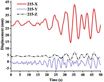
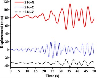
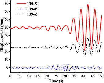
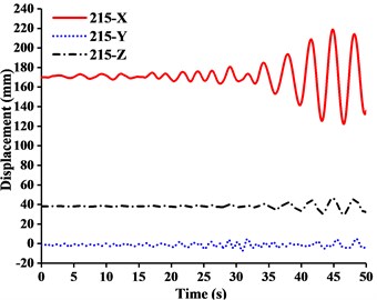
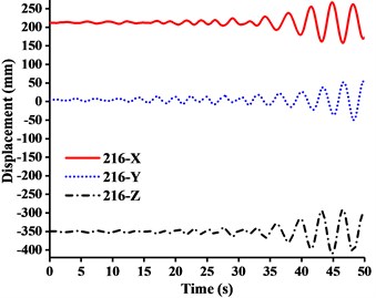
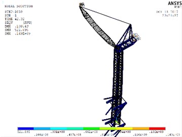
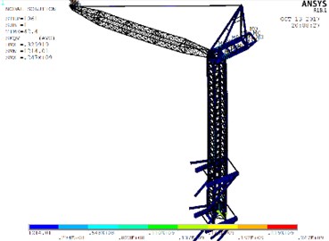
The aim of multi-dimensional input Ludian seismic wave was to evaluate the overall movement of tower crane under simulation of real seismic process. By comparing the time-history analysis result of crane models under WC-1, WC-2 and WC-3, the main concern was concentrated on the displacements of four nodes of important structural members, including No. 216 node (the jib head), No. 139 node (the end of balance arm), No. 183 node (the mast top), and No. 215 node (the A-frame top). The displacement-time history curves of four nodes under three-dimensional Ludian seismic wave were shown in Figs. 11-13. Fig. 14 showed the stress nephograms of crane models when the max unidirectional displacement of nodes occurred.
Fig. 10EI Centro seismic ground acceleration curve
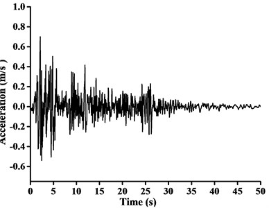
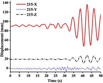
Fig. 11Displacement-time curves of WC-1 under three-dimensional Ludian seismic wave: a) No. 139 node, b) No. 183 node, c) No. 215 node, d) No. 216 node
a)
b)
c)
d)
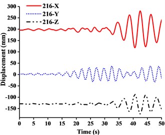
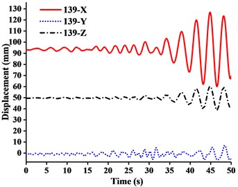
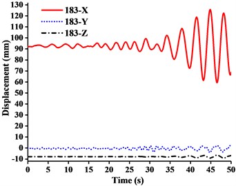
It can be seen from the Figs. 11-14 that:
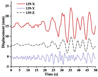
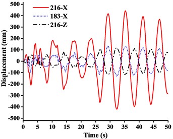
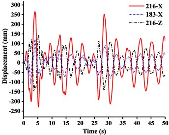
(1) Figs. 11-13 showed that the nodal displacements oscillated about and approach the static values due to the seismic excitation. The initial displacements of four nodes in -direction and z-direction was not zero under self-gravity. Due to the static action of payload on the jib head, the displacement of jib head was always the maximum at any time of seismic duration. The maximum amplitude of dynamic response of nodal displacements was greater than the static displacement. Taking No. 216 node of WC-2 in Fig. 12(d) as an example, the dynamic amplification factors of displacement are 1.43, 16.3 and 1.35, respectively in , and -direction (vertical direction). Therefore, the earthquake excitation had a significant influence on boom tower crane under fully loaded working conditions.
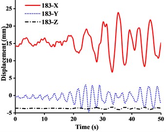
(2) From Figs. 11-13, it was found that the displacement of -direction was always closed to zero under all working conditions. The nodal displacements were concentrated in -direction or -direction. In comparison, the relative displacement in -direction was negligible. The oscillation wave crest had significantly hysteresis action with jib angle decreasing. Figs. 12 and 13 showed that when the earthquake continued to about 35.0 s, the amplitude got larger drastically in the last 15.0 s. From the point of view of structure form, it is indicated that the heavy weight or the payload is equal to a damper because of its inertia. Once it absorbs a certain amount of earthquake energy, the jib and tower are going to absorb seismic energy directly, which leads to a sudden stronger vibration consequently. Tower crane may be damaged without warning.
(3) From Fig. 11(d) and Fig. 13(d), we can know that although there was a 75.0 % decrease in the payload, the peak response of the displacement of crane model increased by about 2.6 times on the contrary. It is indicated that the effect of structural form changes is far greater than that of the payload under seismic excitation. The smaller jib angle is, the greater destructive effect of earthquake on working tower crane becomes sharply.
Fig. 12Displacement-time curves of WC-2 under three-dimensional Ludian seismic wave: a) No. 139 node, b) No. 183 node, c) No. 215 node, d) No. 216 node
a)
b)
c)
d)
6.2. Dynamic response under EI Centro earthquake excitation
In order to study dynamic response characteristics and failure modes of tower crane under unidirectional earthquake excitation, the results of dynamic response of No. 216 and No. 183 node and stresses of crane model were presented in Table 5. It showed that under fully loaded working conditions, the displacement responses of crane models in and -direction were mainly controlled by -directional seismic excitation, while the displacement response in -direction was controlled by -directional seismic excitation. The displacement responses were concentrated at the jib head or mast top. Although the amplitude of key nodal displacements became larger from WC-1 to WC-3 under -direction seismic excitation, it was still far less than the displacement induced by the other two directions. Therefore, the effect of -directional earthquake excitation on tower crane was unremarkable.
Fig. 13Displacement-time curves of WC-3 under three-dimensional Ludian seismic wave: a) No. 139 node, b) No. 183 node, c) No. 215 node, d) No. 216 node
a)
b)
c)
d)
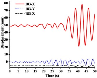
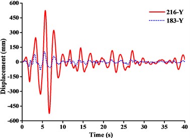
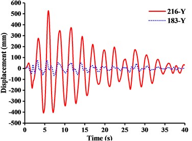
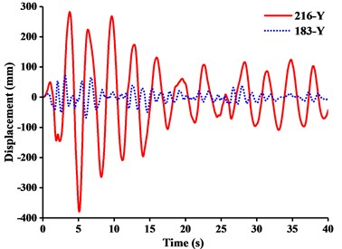
For further investigation on the failure modes or weak parts caused by or -directional seismic excitation, the dynamic responses of the displacement at the jib head (No. 216 node) and the mast top (No.183 node) under or -directional seismic wave were described in Figs. 15 and 16.
The following were summarized from Table 5, Fig. 15 and Fig. 16.
(1) Table 5 showed that the response of stress peak of crane model generated by , , or -direction seismic waves gradually decreases. Under different working conditions, the displacement responses of crane models in and -direction were mainly controlled by -direction seismic waves, while the displacement response in -direction was controlled by -direction seismic waves. The tip displacement of jib was always the largest at any time of seismic duration. Because of the capacity in the tip under -direction seismic excitation, the earthquake would produce inertial acceleration on the lift and caused a cantilever beam load that was far greater than required capacity. And there was also a great vibration of jib from up and down at the same time. Therefore, the -direction seismic wave had the greatest destructive effect on tower crane. It was most likely to cause a broken jib under working conditions.
(2) Fig. 15(a) showed that when under -direction seismic excitation with working condition one (WC-1), the -direction displacement of the jib head was about 3.5 times the -direction displacement. The deformation mode of tower crane was analogous to the cantilever deformation of beam, the end of which was fixed on the ground. The bending stiffness of mast generated by standard mast sections made a major contribution to resisting overturning in plane. Meanwhile the movement of the boom at small angle tended to be independent on the overall structural deformation. Therefore, when the boom was at large or small angle, the tower crane was inclined to be the global or the boom motion system.
(3) Fig. 15 showed that from WC-1 to WC-3 under -direction seismic wave, the -direction displacement of the jib head exceeded the -direction displacement eventually and got close to the -direction displacement of the mast top. It was shown that the movement of jib tended to be independent on the overall structural deformation, instead of being a part of the cantilever deformation of mast.
Table 5The maximum nodal displacements and peak stresses under working conditions
Working condition | Seismic wave direction | No.216 nodal max-displacements in three directions (mm) | No.183 nodal max-displacements in three directions (mm) | Peak stress (MPa) | Peak stress position | ||||
WC-1 | 443 | 8.17 | 123.7 | 136.5 | 2.25 | 5.93 | 234.12 | Boom | |
0.417 | 525 | 0.615 | 1.21 | 103 | 0.0434 | 84.513 | Mast | ||
2.98 | 0.19 | 1.42 | 1.59 | 0.056 | 0.85 | 20.691 | Boom | ||
WC-2 | 266 | 15.4 | 150 | 123.6 | 1.94 | 4.68 | 225.21 | Boom | |
0.84 | 527.9 | 1.09 | 1.0 | 76.9 | 0.0457 | 65.832 | Mast | ||
10.2 | 0.454 | 8.67 | 4.95 | 0.086 | 0.878 | 27.474 | Boom | ||
WC-3 | 342.6 | 30.4 | 376 | 212 | 1.92 | 8.51 | 195.51 | Boom | |
2.1 | 379 | 2.47 | 1.31 | 71.4 | 0.057 | 72.374 | Mast | ||
21.7 | 1.62 | 46.1 | 13.4 | 0.141 | 0.87 | 67.807 | Boom | ||
Fig. 14Stress nephograms of models when the max unidirectional displacement of nodes occurs: a) WC-1, b) WC-2, c) WC-3
a)
b)
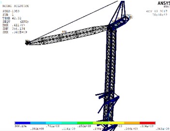
c)
Fig. 15Displacement-time curves under x-direction seismic excitation: a) WC-1, b) WC-2, c) WC-3
a)
b)
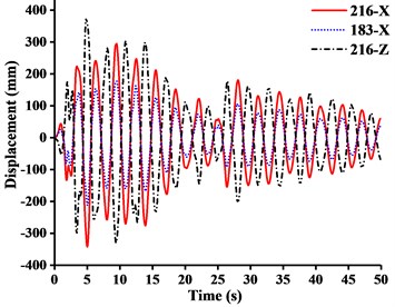
c)
Fig. 16Displacement-time curves under y-direction seismic excitation: a) WC-1, b) WC-2, c) WC-3
a)
b)
c)
7. Conclusions
The study on seismic response regularities of tower crane and anti-seismic measures adopted accordingly are of fundamental importance for both the design and operation of such boom tower crane. Simplified finite-element models under different fully loaded working conditions are derived based on the principle for extreme condition. By investigating the dynamic characteristics and conducting dynamic response analysis under different seismic waves, it can be concluded that:
1) From the point of view of dynamics, the jib angle contributes to the stiffness distribution of whole crane structure, and its influence on dynamic properties is mode-dependent. The sensitivities of different modes to the change of jib angle are significantly distinct. With the change of jib angle, great changes are taken place in structural style of tower crane. Simultaneously, there are different damage forms under seismic load. Precautions can be taken for those different situations. Especially when tower crane occurs an earthquake with large acceleration along the longitudinal direction of jib (-direction), some measures need to be taken in advance to reduce vibration in case of broken jib.
2) The seismic wave has a significant effect on boom tower crane under fully loaded working conditions. The change of structural forms produces a greater impact on seismic responses than the change of payload. When the jib angle decreases, the peak response of displacements of tower crane increases. Although lifting heavy object, to some extent, could be regarded as inertial damper, the amount of seismic energy absorption is of strong uncertainty. A sudden aggravated vibration may cause tower crane collapsing with unpredictability. Thus, the smaller jib angle is, the greater destructive effect of earthquake on working tower crane becomes sharply. When tower crane in operation, the jib should be adjusted to be in large angle.
References
-
Tam Vivian W. Y., Fung Ivan W. H. Tower crane safety in the construction industry: A Hong Kong study. Safety Science, Vol. 49, Issue 2, 2011, p. 208-215.
-
Xie R., Tian T. M., Tian Q. Damage causes of tower cranes during Wenchuan earthquake in Xi’an city. Crgoes Handling Machines, Vol. 4, 2009, p. 1-3.
-
Eihab Abdel Rahman M., Ali Nayfeh H., Ziyad Masoud N. Dynamics and control of cranes: a review. Journal of Vibration and Control, Vol. 9, 2003, p. 863-908.
-
Wang S. C., Shen R. S., Jin T. H., et al. Dynamic behavior analysis and its application in tower crane structure damage identification. Advanced Materials Research, Advances in Civil Engineering and Architecture Innovation, Vol. 368, Issue 373, 2012, p. 2478-2482.
-
Shapira A., Elbaz A. Tower crane cycle times: case study of remote-control versus cab-control operation. Journal of Construction Engineering and Management, Vol. 140, Issue 12, 2014, p. 5014010.
-
Li Y. L., Ai B., Li B. The damage cause of tower crane under earthquake action and the status of dynamic analysis. Special Structures, Vol. 28, Issue 2, 2011, p. 66-68, (in Chinese).
-
Shen T., Yan W. M., Zhou D. X., et al. TMD control and analysis of cranes under earthquake. Technology for Earthquake Disaster Prevention, Vol. 12, Issue 2, 2017, p. 276-287.
-
Feng J., Yoo S. C. Dynamic analysis of tower cranes. Journal of Engineering Mechanics, Vol. 131, Issue 1, 2005, p. 88-96.
-
Hazriq I. J., Mohamedb Z., Jamianb J. J., et al. Dynamic behaviour of a nonlinear gantry crane system. Procedia Technology, Vol. 11, 2013, p. 419-425.
-
Huang L. J., Syu H. J. Seismic response analysis of tower crane using SAP2000. Procedia Engineering, Vol. 79, 2014, p. 513-522.
-
He Y. H., Gu L. C., Ji P. B. Seismic analysis of tower crane based on ANSYS. Machinery Design and Manufacture, Vol. 7, 2012, p. 188-190.
-
Abuduwalisi, Yu R. F., Yu Y. X. Spatial variation of ground motions based on Wenchuan acceleration records. Journal of Vibration and Shock, Vol. 32, Issue 16, 2013, p. 70-75.
-
Şahin Y., Levent M., Hira K. Analysis of active vibration control of multi-degree-of-freedom flexible systems by Newmark method. Simulation Modelling Practice and Theory, Vol. 69, 2016, p. 136-148.
-
Ai B., Yang J., Lin Pei, Zeng Z. Seismic response analysis of tower crane in consideration of the building-crane interaction. Applied Mechanics and Materials, Advances in Civil and Industrial Engineering, Vols. 353-354, 2013, p. 1981-1985.
-
Lee G., Suyeul P., Cho J. B. Analysis of field applicability of the rotation-controllable tower crane hook block. Automation in Construction, Vol. 21, Issue 1, 2012, p. 81-88.
-
Sohn H., Won K., Lee Dd H., et al. Optimum tower crane selection and supporting design management. International Journal of Advanced Robotic Systems, Vol. 133, Issue 11, 2014, https://doi.org/10.5772/58438.
-
Mara T. G. Effects of a construction tower crane on the wind loading of a high-rise building. Journal of Structural Engineering, Vol. 136, Issue 11, 2010, p. 1453-1460.
-
Wei X. D., Wu X. H., Qian J., et al. Research on nonlinear time-history response of a multi-tower connected structure subjected to vertical earthquake motion. Building Structure, Vol. 42, Issue 6, 2012, p. 121-126, (in Chinese).
About this article

This study is financially supported by the national 13th five-year key research and development program of China (2016YFC0701909-1), Fundamental Research Funds for the Central Universities (106112017CDJXY200009, 106112016CDJRC000101), China Construction Second Engineering Bureau Ltd.
