Abstract
Experimental researches of a vertical rotor with a ball-type automatic balancer with a circular cross-section of the body have proved its efficiency in the reduction of vibrations of an out-of-balance rotor, however for acceleration of compensating masses till the rotor working velocity it is necessary to set initial velocity. A value of the initial velocity of compensating masses depends on the stiffness of the elastic rotor suspension. At the same time, real elastic suspensions of rotors possess nonhomogeneous elastic dissipative characteristics in directions. The research is aimed at determining the influence of anisotropy of the elastic rotor suspension on the acceleration of compensating masses. The authors give recommendations on the selection of parameters of a rotor suspension.
1. Introduction
A ball-type autobalancing device (hereinafter ABD) allows reducing the disbalance of a rotating out-of-balance rotor on an elastic suspension in the superresonance zone of frequencies. In terms of sensitivity the most efficient is the ABD with a torus-shaped body with the circular cross-section, where circular-shaped compensating masses (hereinafter CM) are freely displaced. However, the acceleration of compensating masses till velocity of the rotor’s rotation depends on many parameters of the rotor systems, among which we can mention stiffness of the elastic suspension of the rotor, a coefficient of friction of CM rolling on ABD inner surface [1].
At the same time, for the acceleration of ABD compensating masses in certain cases it is necessary to provide initial velocity [2], otherwise CM steadily move towards ABD body (unsteady operating regime), which leads to increased rotor vibrations. It is obvious that the damping coefficient depends on the suspension stiffness; however, the impact of parameters of the elastic suspension on CM acceleration has been studied insufficiently. Besides, there is no information on the influence of anisotropic elastic suspension of a rotor on the acceleration of ABD compensating masses. In the work [3, 6] we studied the constructions and stability of the autobalancing regime depending on parameters of viscous friction in АBD and in the suspension of the rotor system with a horizontal rotation axis. Therefore, there is certain interest in determining the influence of parameters of the elastic dissipative rotor suspension on the performance of the torus-shaped autobalancing device with a vertical rotation axis in the regime of CM acceleration. The results of the research can be used at the design of an elastic suspension of rotor systems with ABD having torus-shaped body.
The aim of the research is to analyze the process of acceleration of compensating masses of ABD fixed on the rotor with vertical rotation axis on the anisotropic elastic suspension and to determine the conditions for its reliable acceleration. This work is the continuation of work [1] and is based on experimental trials of rotors with ABD [4].
2. Calculation scheme and mathematical model of a rotor with an automatic balancer
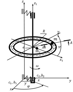
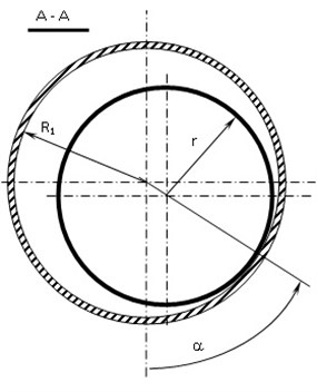
The authors study a symmetric vertical stiff rotor on the anisotropic elastic dissipative suspension and with ABD. The body of the automatic balancer is torus-shaped with radius on the average circumference and in the cross-section where one ball-shaped compensating mass with radius and mass is placed. The rotor with mass possesses static eccentricity . The rotor is fixed on the anisotropic elastic suspension, whose coefficients of stiffness and viscous damping in the directions of axes and equal , and , accordingly. During the research it was accepted that the value of dissipation coefficients and is proportional to the stiffness of the suspension in the corresponding direction. The body of the ABD is concentrically fixed on the rotor and rotates together with it with angular velocity .
The calculation scheme of the rotor with ABD shown in Fig. 1 is described in detail in [1]. The system of differential equations of movement describing the movement of the rotor system with ABD, which are given in [1], are specified according to the task.
Fig. 1Calculation scheme for the rotor system with ABD
Taking into account that rotation velocity is constant ( const, ), and for the convenience of numerical solution of the set of equations [1] we will present parameters of the rotor system in a dimensionless aspect:
where – dimensionless time.
The task is solved at the constant value of the coefficient of viscous damping ( const) and with the coefficient proportional to the stiffness of the suspension ( – proportionality coefficient).
At the numerical solution of differential equations we accept 1 m and 1 s-1. At doing the practical task for obtaining real values of the calculation results, they are to be multiplied by specific values and :
where – dimensionless force of normal pressure of the ball onto the inner surface of ABD body:
The calculation results of the system of differential Eqs. (1-4) are obtained in the form of dimensionless velocities and coordinates:
3. Research results of the mathematical model
The differential Eqs. (1-4) of movement of the rotor system with ABD were investigated by means of SPRING software [5].
The authors research the influence of asymmetric stiffness of the elastic rotor suspension on the conditions of CM acceleration till velocity of rotor rotation. Thus, we determined the initial velocity of CM in a circumferential direction of the balancer (at the initial conditions CМ 0, 0, 0, ) at which its acceleration till working velocity of the rotor is provided. The initial conditions of the rotor at the study of CM acceleration are accepted as follows: 0, 0, 0, 0, 0, 1.
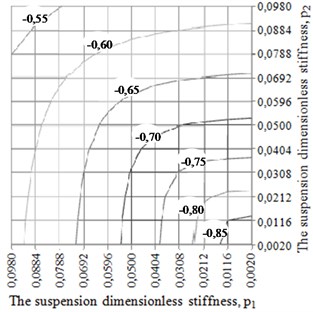
At the first stage of the research it was accepted that the dissipation coefficient in the elastic rotor suspension does not depend on stiffness of the suspension and remains constant. The trials of CM acceleration were performed at two fixed values of the coefficient of relative dissipation: 0,35 and 0,035 and at the following parameters of the rotor systems: 0,005; 2,5; 15; 200; 0,0024; 0,5005. The calculation results are given in Table 1 and were used for construction of charts in Fig. 2 showing the dependence of the initial velocity of CM in the circumferential direction of ABD body on the value of dimensionless stiffness of anisotropic rotor suspension. The trials were carried out at a ratio of working rotor velocity to fundamental frequencies of the elastic suspension of the rotor system within: 3,194…22,36 and 1,…, 7.
Table 1The initial velocity of the compensating mass in the circumferential direction of the balancer v3
= 0,035 | The suspension dimensionless stiffness, | |||||
0,0020 | 0,0308 | 0,0500 | 0,0692 | 0,0980 | ||
The suspension dimensionless stiffness, | 0,0020 | –0,9075 | –0,7638 | –0,7083 | –0,6626 | –0,6043 |
0,0308 | –0,7600 | –0,7359 | –0,6970 | –0,6562 | –0,6006 | |
0,0500 | –0,7035 | –0,6945 | –0,6766 | –0,6466 | –0,5962 | |
0,0692 | –0,6571 | –0,6522 | –0,6444 | –0,6281 | –0,5884 | |
0,0980 | –0,5979 | –0,5952 | –0,5918 | –0,5857 | –0,5663 | |
= 0,35 | The suspension dimensionless stiffness, | |||||
0,0020 | 0,0308 | 0,0500 | 0,0692 | 0,0980 | ||
The suspension dimensionless stiffness, | 0,0020 | –1,000 | –0,4888 | –0,4334 | –0,3884 | –0,3313 |
0,0308 | –0,4887 | –0,4199 | –0,3813 | –0,3463 | –0,2984 | |
0,0500 | –0,4332 | –0,3812 | –0,3493 | –0,3191 | –0,2763 | |
0,0692 | –0,3882 | –0,3461 | –0,3190 | –0,2926 | –0,2541 | |
0,0980 | –0,3309 | –0,2981 | –0,2761 | –0,2540 | –0,2208 | |
Fig. 2The chart of the dependency of CM initial velocity v3 in the circumferential direction of ABD body on the value of dimensionless stiffness of the rotor suspension p1 and p2 at the following values of dimensionless parameters: m0= 0,005; e0= 2,5; e1= 15; e2= 200; kr= 0,0024; g0= 0,5005 a) n= 0,035; b) n= 0,35
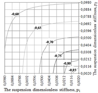
a)
b)
Table 1 and the charts (Fig. 2) make it clear that anisotropy of the elastic rotor suspension influences the value of CM initial velocity. The increase of the suspension stiffness (parameter “”) in any direction leads to the necessity to increase absolute initial velocity of the compensating mass for its acceleration till the working velocity of the rotor. Vice versa, the reduction of stiffness of the rotor suspension in any direction allows decreasing the absolute velocity of CM. Thus, the increase of the dissipation coefficient in the rotor suspension leads to the necessity to increase the absolute velocity of CM for its acceleration till rotor velocity.
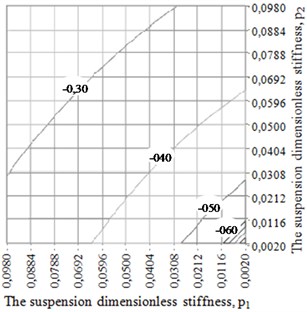
At the second stage of the research it was accepted that the dissipation coefficient in the elastic rotor suspension is proportional to the stiffness of the suspension, i.е. ; . The trials of CM acceleration were carried out at two values of proportionality coefficient ( 0,7 and = 7,0), which correspond to the values of relative dissipation in Table 1 at 0,05 (average value in a range of relative stiffness). Other parameters of the rotor system did not change. The research results are summarized in Table 2 and in Fig. 3. As may be seen from the analysis of Table 2 and Fig. 3 anisotropy of the dissipation coefficient of the suspension makes essential impact on CM acceleration in ABD.
Table 2The initial velocity of the compensating mass in the circumferential direction of the balancer v3
0,7 | The suspension dimensionless stiffness, | |||||
0,0020 | 0,0308 | 0,0500 | 0,0692 | 0,0980 | ||
The suspension dimensionless stiffness, | 0,0020 | –0,9355 | –0,7774 | –0,7129 | –0,6586 | –0,5881 |
0,0308 | –0,7714 | –0,7519 | –0,7018 | –0,6506 | –0,5815 | |
0,0500 | –0,7078 | –0,6992 | –0,6766 | –0,6370 | –0,5729 | |
0,0692 | –0,6540 | –0,6475 | –0,6356 | –0,6115 | –0,5591 | |
0,0980 | –0,5841 | –0,5783 | –0,5708 | –0,5578 | –0,5249 | |
7,0 | The suspension dimensionless stiffness, | |||||
0,0020 | 0,0308 | 0,0500 | 0,0692 | 0,0980 | ||
The suspension dimensionless stiffness, | 0,0020 | –0,9420 | –1,0000 | –1,0000 | –1,0000 | –1,0000 |
0,0308 | –0,9873 | –0,5464 | –0,4633 | –0,4191 | –0,4422 | |
0,0500 | –0,9874 | –0,4640 | –0,3493 | –0,2696 | –0,2054 | |
0,0692 | –0,9872 | –0,4204 | –0,2701 | –0,1612 | –0,0395 | |
0,0980 | –0,9865 | –0,4442 | –0,2064 | –0,0400 | –0,0000 | |
Fig. 3The chart of the dependency of CM initial velocity v3 in the circumferential direction of ABD body on the value of dimensionless stiffness of the rotor suspension p1 and p2at the following values of dimensionless parameters: m0= 0,005; e0= 2,5; e1= 15; e2= 200; kr= 0,0024; g0= 0,5005 a) μ= 0,7; b) μ= 7,0
a)
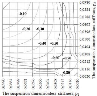
b)
4. Conclusions
In the result of performed calculations of the mathematical model for a vertical rotor with concentrically fixed torus-shaped ABD body with a circular cross-section, it has been stated that CM acceleration till rotor working velocity essentially depends on anisotropy of stiffness and dissipation coefficients of the elastic rotor suspension. Thus, the increase of anisotropy of the elastic rotor suspension towards the reduction of stiffness coefficient in one direction and the increase of dissipation leads to the reduction of necessary initial absolute CM velocity in the circumferential direction ABD for its acceleration till rotor velocity. For successful CM acceleration it is recommended to introduce temporary (for the time of acceleration) artificial anisotropy into the design of a rotor suspension.
References
-
Strautmanis G., Mezitis M., Strautmane V. The impact of rotor elastic suspension settings on the acceleration of the automatic balancer compensating mass. Vibroengineering Procedia, Vol. 14, 2017, p. 13-17.
-
Strautmanis G., Grinevich I., Strautmane V. The influence of automatic equalizer and rotor parameters on the ball’s motion mode. Mechatronic Systems and Materials, 2015, p. 135-141.
-
Gorbenko A. Analytical determination of the stability movement boundaries of the Jeffcott rotor with multi-bodies autobalancer. Vibroengineering Procedia, Vol. 8, 2016, p. 152-157.
-
Strautmanis G., Jurjevs V., Cokalo V. A Balancing Device for Centrifuges of Washing Machines. LV Patents, LV 14368 B, 20.10.2011, (in Latvia).
-
Ščukins I., Zakrževskis M., Ivanov Y., et. al. Application of software SPRING and method of complete bifurcation groups for the bifurcation analysis of nonlinear dynamical system. Journal of Vibroengineering, Vol. 10, Issue 4, 2008, p. 510-518.
-
Fіlіmonіhіn G.B. Balancing and Vibration Protection of Rotors by Autobalancers with Solid Corrective Weights. Kirovograd, KNTU, 2004, p. 352, (in Ukrainian).
About this article

