Abstract
Abrasive flow machining has become an economical and efficient ultra-precision process for machining complex-shaped pipe parts, and processing effect is exceedingly subject to particle volume fraction. In this paper, aiming at uncovering the influence of various particle volume fractions on the machining result of abrasive flow finishing, based on fluid mechanics theory, mixed phase model and discrete phase model were conducted, FLUENT software was resorted to simulate the numerical characteristics of the solid-liquid two-phase flow field in the inner channel of S-tube with different-particle-volume-fraction abrasive flows, the mechanism of erosion and wear of particles was uncovered, which provides a theoretical basis for abrasive flow machining S-tube structured components.
1. Introduction
Abrasive Flow Machining (referred to as AFM), also known as extrusion grinding or extrusion honing, is mainly used for polishing shaped holes and complex cavities and other workpieces traditional methods are inadequate to process [1, 2]. Abrasive flow machining technology was developed in the United States last century. This deburring process of the alloy workpiece with complex geometry, originally used in aerospace field, has been applied in many fields with decades of development. Abrasive flow polishing technology can be used to serve performances, such as machining micro holes and polishing complex channel inner surface.
With the rapid development of industry, medical treatment and machinery industry, space elbows have been widely used in the fields of engines, gas transportation, fluid transportation [3, 4]. Pressing and bending processes will generate folds, pits and other surface defects on the inner surface of the pipe, resulting in fluid congestion and pressure fluctuation in the tube, which makes the work of the component unstable and inefficient. Therefore, it is very important to improve the surface precision by the finishing of the inner surface of elbow workpieces [5, 6]. Given the high processing efficiency of abrasive flow, the surface morphology of the workpiece is compact and uniform after processing proved by practical experience [7-9].
2. Numerical simulation for machining S-tube
In this paper, high precision dispensing needle as the research object. The surface processing characteristics of the solid-liquid two-phase abrasive grains were numerically simulated. Ensuring that the inlet pressure and the outlet pressure are constant, the effects of the volume fraction of silicon carbide particles on the dynamic pressure and turbulent kinetic energy during the high-precision process were studied.
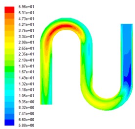
After the non-structured hexahedral mesh is divided into the inner channel S-tube model, based on the actual situation, set the import and export pressure boundary conditions for numerical simulation, inlet pressure to 6 MPa. The volume fraction of silicon carbide was respectively set to be 0.1, 0.15, 0.2 and 0.25. The simulation results of the multi-physics coupling field with four volume fractions are obtained. Fig. 1 shows the dynamic pressure cloud image at different volume fractions.
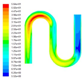
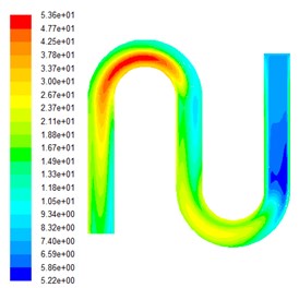
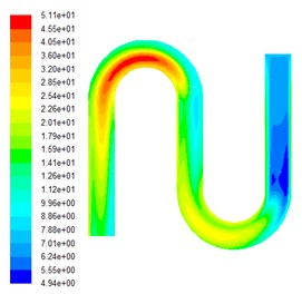
Fig. 1Dynamic pressure cloud diagrams under various particle volume fractions
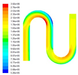
a) The particle volume fraction is 0.1
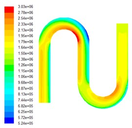
b) The particle volume fraction is 0.15
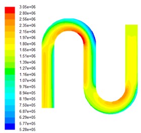
c) The particle volume fraction is 0.2
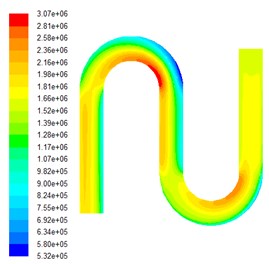
d) The particle volume fraction is 0.25
As can be seen from Fig. 1, the dynamic pressure value stratification is very obvious until the end of the second bend. It is worth noting that at the two bends, the inner pressure is greater than the outside one, and the pressure value is minimized at the outside of the first bend, while reaching the maximum on the inside, which indicates that where the abrasives have greatest ability to achieve grinding performance. The pressure distribution at the second bend is more even than those of the first bend. In addition, the pressure distribution, at the straight pipe section before the outlet, is relatively uniform and the overall size is small because of energy dissipation.
Select the inside section at the entry as data 1 area, the inside section of the first bend as data 2 area, and the inside section of the second bend as data 3 area, the numerical values of the dynamic pressure values in the three data areas are listed in Table 1.
Table 1Dynamic pressure data distribution table
Particle volume fraction | Dynamic pressure (105MPa) | ||
Data 1 area | Data 2 area | Data 3 area | |
0.1 | 12.5 | 30.2 | 23.2 |
0.15 | 12.6 | 30.3 | 23.3 |
0.2 | 12.7 | 30.5 | 23.5 |
0.25 | 12.8 | 30.7 | 23.6 |
It can be concluded from Table 1 that the pressure values of the three regions all increases with the increase of the particle concentration. This is because with the raising of particle volume fraction, abrasive particles contact the workpiece surface area more often, the grinding effect on the wall of the workpiece increases, thereby improving the abrasive flow on the workpiece surface polishing effect.
Under the same initial conditions, the numerical simulation of the turbulence viscosity in the grinding process of the workpiece under different volume fraction is carried out. The turbulence viscosity cloud images with different particle volume fraction are shown in Fig. 2.
Fig. 2Turbulent kinetic energy diagrams under different volume fractions
a) The particle volume fraction is 0.1
b) The particle volume fraction is 0.15
c) The particle volume fraction is 0.2
d) The particle volume fraction is 0.25
It can be seen from the turbulent kinetic energy diagram under different volume fraction of Fig. 2, due to the movement of viscoelastic silicon carbide abrasives in turbulent state, under the same inlet pressure boundary conditions, with the increase of the abrasive volume fraction, turbulence viscosity increases, due to the velocity gradient and viscoelasticity of the fluid, will inevitably lead to abrasive grain on the workpiece surface friction, so the abrasive particle volume fraction increases, the turbulence viscosity increases, thus improving the polishing effect of the workpiece.
What’s more, during the flow process, due to the presence of energy dissipation, turbulent kinetic energy at the first curve is significantly larger than that of second one. So, transferring the flow entrance to the exit after a period of processing to continue machining is a wise way to ensure the processing effect.
3. Conclusions
Through the numerical analysis for machining S-tube by abrasive flow with various particle volume fractions, the effect of volume fraction of silicon carbide on the processing effect was simulated by changing the amount of solid-liquid two-phase abrasive grains. The changes of dynamic pressure and turbulent viscosity in the process are analyzed, it can be inferred that in a certain range, the greater particle volume fraction is, the greater the dynamic pressure and turbulent kinetic energy of the grinding effect are, and the better the polishing effect of abrasive grain flow would be.
References
-
Sun Fengyu, Wei Lili, Li Junye, Zhang Xinming, Xu Ying The single factor experiment of the non-linear tube in abrasive flow machining. Journal of Measurements in Engineering, Vol. 5, Issue 1, 2017, p. 15-19.
-
Li Junye, Wei Lili, Zhang Ximing, Hu Jinglei, Su Ningning Quality analysis of T-tube with solid-liquid two-phase abrasive flow polished. Journal of Measurements in Engineering, Vol. 5, Issue 2, 2017, p. 67-88.
-
Ding Jinfu, Liu Runzhi, Zhang Kehua, et al. Micro cutting mechanism of abrasive flow precision machining. Optics and Precision Engineering, Vol. 22, Issue 12, 2014, p. 3329-3333.
-
Li Junye, Hu Jinglei, Su Ningning, et al. Numerical analysis in viscosity-temperature characteristics of solid-liquid two-phase abrasive flow polishing. Journal of Measurements in Engineering, Vol. 5, Issue 3, 2017, p. 105-113.
-
Li Junye, Xu Ying, Yang Lifeng, et al. Experimental study on grinding flow of non-linear tube parts. China Mechanical Engineering, Vol. 25, Issue 13, 2014, p. 1733-1743.
-
Li Dingpeng, Qian Jianping, Huang Weiping, et al. Numerical simulation of flow field in rotating drive. Ordnance Automation, Vol. 34, Issue 5, 2015, p. 14-17.
-
Li Junye, Su Ningning, Zhao Weihong, Yin Yanlu, Hu Jinglei Study on the polishing of curved pipe parts by solid liquid two phase abrasive flow. Journal of Measurements in Engineering, Vol. 5, Issue 2, 2017, p. 59-67.
-
Li Junye, Liu Weina, Yang Lifeng, et al. Numerical simulation of the behavior of grape flow in the micro-hole of injector. Coal Mine Machinery, Vol. 31, Issue 10, 2010, p. 59-66.
-
Wan S., Ang Y. J., Sato T., et al. Process modeling and CFD simulation of two-way abrasive flow machining. International Journal of Advanced Manufacturing Technology, Vol. 71, Issues 5-8, 2014, p. 1077-1086.
About this article

The authors would like to thank the National Natural Science Foundation of China No. NSFC 51206011, Jilin Province Science and Technology Development Program of Jilin Province No. 20160101270JC and No. 20170204064GX.
