Abstract
Power split two-stage five-branching star gearing drive system has been widely used in the aviation engine reducer and the helicopter’s main reducer. For the problem of load sharing characteristics of this system, a static load-sharing calculation model is established. According to the power flow closed loop characteristics of the whole system, the torque equilibrium condition and deformation compatibility condition of the system are established. The load sharing coefficient of the star gears and the system is calculated by using the principle of the integrated equivalent mesh error and the static equilibrium condition of the floating element. Further, the influence of manufacturing error, installation error and floating on load sharing coefficient is analyzed. When the load sharing characteristic is independently influenced by the error, the load sharing coefficient of each star gear changes periodically with time. Basic component floating can significantly improve the load sharing performance. The correctness of the theoretical algorithm is verified by experiments. A new algorithm is proposed for engineering application.
1. Introduction
Power split two-stage five star gearing drive system has been widely used in the aviation engine reducer and the helicopter’s main reducer. Load sharing technology is adopted for power split star gearing transmission, which has the advantages of small size, light weight and strong bearing capacity. However, in practical engineering application, due to the inevitable errors of manufacture and installation, and the elastic deformation, the system cannot achieve the average distribution in the process of transferring load. Therefore, it is very important to solve the problem of uneven load distribution among the stars, and it is very important to make full use of its superiority.
At present, domestic and foreign scholars have carried out some research on the load sharing characteristics of the power split gear transmission. By considering the displacement coordination conditions, the load sharing characteristics of the two-stage star gear transmission system are studied by Mo et al. [1], and the experimental verification is carried out. Du et al. [2] studied the load sharing behavior of planetary train based on deformation compatibility. Dong et al. [3, 4] studied the load sharing characteristics of two-branching power split system based on deflection compatibility and clearance floating. Guo et al. [5] studied load sharing of wind turbine planetary gear drivetrains subjected to non-torque loads. Park et al. [6] studied load sharing and distributed on the gear flank of wind turbine planetary gearbox. Sekar et al. [7] studied load sharing based maximum fillet stress analysis of asymmetric helical gears designed through direct design. Sun et al. [8] give a study on load-sharing structure of multi-stage planetary transmission system. Yu et al. [9] studied sharing behavior of load transmission on gear pair systems actuated by parallel arrangements of multiple pinions. Montestruc et al. [10] give a numerical approach to calculation of load sharing in planetary gear drives. Singh et al. [11] studied load sharing behavior in epicyclic gears: physical explanation and generalized formulation. Soojin et al. [12] studied the tooth load sharing and deformation overlap of helical gear pairs for the manual transmission of automobile. Gill et al. [13] analyze the influence of bearing stiffness on the static properties of a planetary gear system with manufacturing errors. Ashraf et al. [14] studied the peak load sharing based on blade pitch control of wind turbine in the presence of utility supply. Boguski et al. [15] proposed a new method to measure planet load sharing and sun gear radial orbit of planetary gear sets. Gu et al. [16] proposed a dynamic model to study the influence of planet position errors in planetary gears. Kim et al. [17] studied the effects of bearing internal clearance on the load distribution and load sharing in the pitch reducer for wind turbines. Wei et al. [18] studied the dynamic analysis and load-sharing characteristic of multiple pinion drives in tunnel boring machine. Li et al. [19] studied the load sharing characteristics of multi-stage planetary gear train through using analytical and finite element model. Wang et al. [20] studied the electromechanical dynamic simulation and experiment for multi-stage gear transmission system with planetary gears. Zhang et al. [21] carried out the analysis of transmission error and load distribution of a hoist two-stage planetary gear system. Sun et al. [22] established a dynamical model of two-stage helical planetary gear transmission system through using the lumped-parameter method and Lagrange general function. He studied the dynamic load sharing structure of multi-stage planetary transmission system. In addition, there are still many scholars to study the load sharing characteristics of the power split gear transmission system [23-28]. Therefore, studying the load sharing characteristics of multi-stage star gear transmission system is of great significance for its rational design and success.
The physical and mathematical models of the two-stage five-star gear transmission are established in this paper. The deformation coordination condition of the system is derived, and the calculation method of the load distribution coefficient of the two stage five-star gear transmission system is studied. The influence of manufacturing error and installation error on the power flow characteristics of star gear transmission system is analyzed, and the formula for calculating the equivalent meshing error is derived. The influence of error on system power distribution is compared, and the error factors that affect the power distribution of the system are found. The influence of floating parts on the power distribution characteristics of the system is studied. Finally, experimental verification is carried out and compared with the theoretical results.
2. Establishment of equivalent mechanical model
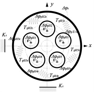
Fig. 1 shows kinematic diagram of two-stage five-branching internal and external mesh star gear transmission.
Fig. 1Kinematic diagram of two-stage five-branching internal and external mesh star gear transmission
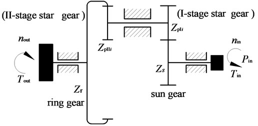
Here, the input power is assigned to the I-stage star gear ( 1, 2, …, 5) through the sun gear , and then, flow into the ring gear through the II-stage star gear . Fig. 2 shows computational model of two-stage five-branching internal and external mesh star gear transmission.
Fig. 2Computational model of system
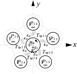
a) Schematic diagram of the I-stage gear movement
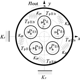
b) Schematic diagram of the II-stage gear movement
The star gear mechanism is considered as a rigid body, the sun gear and ring gear is considered as the basic floating element. The elastic deformation and meshing stiffness of each gear pair in the system are replaced by the equivalent spring model. Here, is the meshing stiffness between the sun gear and the star gear, and is the meshing stiffness between the stars and the ring gear. and represent the equivalent spring stiffness of the support of the sun gear and the ring gear. is the I-stage star gear. is the II-stage star gear.
Here, is engaging force between the sun and the I-stage star gear. is engaging force the II-stage star gear and ring gear. is the transmission torque between the sun gear and the I-stage star gear. is the transmission torque between the II-stage star gear and the ring gear.
As shown in Fig. 2, according to the relationship between the meshing torque, the mechanical equilibrium conditions can be obtained as follows:
Here, is the base circle radius of the first stage star gear. is the base circle radius of sun gear. is input torque. Fig. 3 shows relationship diagram between the torsion angle of each gear of two-stage five-branching internal and external mesh star gear transmission.
Fig. 3Relationship diagram between the torsion angle of each gear of system
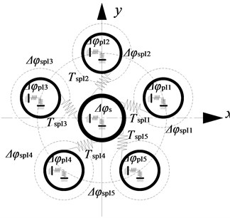
a) Torsion angle of the I-stage gear
b) Torsion angle of the II-stage gear
Here, is torsion angle of the I-stage star gear. is torsion angle of the II-stage star gear. is torsion angle of the sun gear. is torsion angle of the ring gear. is angular distortion of the sun gear under the influence of torque relative to the I-stage star gear. is a function of . is angular distortion of the II-stage star gear under the influence of torque relative to the ring gear. is a function of . As shown in Fig. 3, the gear pair meshing angle meets the following formula:
Here, is the base circle radius of the II-stage star gear. is the base circle radius of ring gear. represents the gear , 1, 2, …, 5.
is a function of , can be expressed as follows:
Due to , the deformation coordination condition can be obtained as follows:
In order to facilitate the analysis error's effect on the load distribution, the error excitation reflected in the direction of the meshing line on the displacement excitation of , which should be projected to the direction of the meshing line, as shown below:
Here, and is axis deformation of gear . and is axis deformation of gear . and is the error amplitude of x direction of gear and gear . and is the error amplitude of direction of gear and gear . is the angle between the gear pair meshing line and the axis.
The engaging force of the gear pair can be expressed as:
Under the influence of error, the meshing angle of the gear pair can be expressed as follows:
3. Comprehensive meshing error analysis of two stage star gear system
The equivalent combined meshing errors of the star gear transmission system are composed of two kinds of errors. The one is that the cumulative meshing backlash caused by the manufacturing and installation errors of the components, that is, cumulative mesh error. The other is the meshing backlash caused by the floating of the components, that is, floating engagement error.
3.1. Cumulative errors caused by manufacturing and installation errors
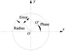
The manufacturing errors that affect the load distribution of the star gear system include the eccentric error of the center of the sun, the stars and the ring gear. The installation error mainly includes the assembly error of the center of the sun, the stars and the ring gear. The eccentricity error and assembly error are represented by and respectively. The direction of each error is represented by the and . , , and are the subscript symbols. They are respectively the sun gear, the I-stage star gear, the II-stage star gear, the ring gear.
Fig. 4 is the schematic diagram of manufacturing or assembly error . , and are the angular velocities of sun gear, star gear, and annular gear. and are working pressure angles of external gearing transmission and internal gearing transmission. refers to the position angle of the th star gear to the first star gear. , is the number of star gear. is time.
Fig. 4Schematic diagram of manufacturing or assembly error of EA
(1) Angular displacement caused by equivalent mesh error in the first stage.
In the first stage, the angular displacement caused by the eccentric error of the sun gear is:
The angular displacement caused by the installation error of the sun gear is:
The angular displacement caused by the eccentric error of the I-stage star gear is:
The angular displacement caused by the installation error of the I-stage star gear is:
(2) Angular displacement caused by equivalent mesh error in the second stage.
In the second stage, the angular displacement caused by the eccentric error of the II-stage star gear is:
The angular displacement caused by the installation error of the second -stage star gear is:
The angular displacement caused by the eccentric error of the ring gear is:
The angular displacement caused by the installation error of the ring gear is:
(3) Angular displacement caused by eccentric error of bearing.
The angular displacement caused by the eccentric error of bearing of the sun gear is:
The angular displacement caused by the eccentric error of bearing of the I-stage star gear is:
The angular displacement caused by the eccentric error of bearing of the II-stage star gear is:
The angular displacement caused by the eccentric error of bearing of the ring gear is:
The sum of above mentioned equivalent meshing error is obtained.
The cumulative angular displacement generated by the manufacturing error and installation error in the I-stage and II-stage is shown as follows:
3.2. Floating meshing errors caused by the basic floating element
There is also a kind of change that can cause the comprehensive engagement error change caused by gap change and of basic floating elements.
It is assumed that the floating displacement of the center of the sun gear are and in the and directions. The floating displacement of the center of the ring gear are and in the and directions:
The floating displacement of the I-stage star gear center is and ( 1, 2, …, 5) in the and directions. The floating displacement of the II-stage star gear center is and ( 1, 2, …, 5) in the and directions:
In Eqs. (21) and (22), is the meshing line direction angle of the sun gear and the I-stage star gear. is the meshing line direction angle of the I-stage star gear and the ring gear. and are as follows:
Meshing error of sun gear and the I-stage star gear is as follows:
Meshing error of the II-stage star gear and ring gear is as follows:
3.3. Floating equilibrium condition of basic component
The supporting rigidity of floating sun gear can be described in Fig. 5. When the spline transmits torque, the friction will be produced between internal and external spline, and can be represented as , here, is the positive pressure between internal and external spline, is friction coefficient.
When the sun gear is floating, the floating quantum is shown as follows:
Here, and are the floating quantum along the -direction and -direction, respectively. is the iterations.
Fig. 5Supporting rigidity of floating sun gear
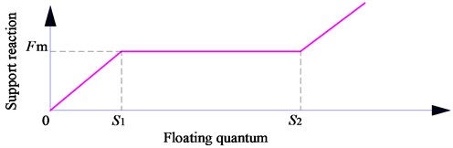
When the bearing reaction force is less than the friction force , between internal and external spline will not slip. When the supporting force is greater than the friction force , the internal spline and the external spline will produce a slip, which is adapted to the position of the floating gear, that is, the - range. When the slip amount exceeds , the internal and external spline eliminates the radial clearance, and the position of the small gear is determined by the bending deformation of the input shaft. - is the radial clearance for internal and external splines.
and represent the support reaction of floating pinion projected on the -axis and -axis, respectively, and can be represented as:
where, is flexural rigidity of spline shaft. is direction angle of vector of and .
The support equilibrium conditions of the floating sun gear can be represented as:
The equilibrium conditions of the floating sun gear are used as the optimization objective. The unknown quantity of the required solution of the component is the optimization variable. The (, ) is used as the optimization variable in the equilibrium position of the floating sun gear. The equilibrium condition of elastic support, the condition of moment equilibrium and the condition of deformation coordination are used as the constraint conditions. A nonlinear mathematical model of the gap based on the floating is established.
The floating balance condition of the ring gear is shown below:
Here, and are the floating quantum of ring gear along the -direction and -direction, respectively. The torque of the gear pair is obtained.
The load-sharing coefficient of the I-stage star gear is shown as follows:
The load-sharing coefficient of the II-stage star gear is shown as follows:
The load sharing coefficient of the system is shown below:
4. Effect of main error on load sharing characteristics
Table 1 is the main parameters of the power split two-stage five-star gearing transmission system. Input power is 220 kW. Input speed is 6800 r/min. The equivalent mesh stiffness of the sun gear and the I-stage star gear is 8.6×10⁹ N/m. The equivalent mesh stiffness of the II-stage star gear and the ring gear is 9.3×10⁹ N/m. Bending rigidity of spline shaft is 1.78×10⁷ N/m. The support stiffness of the ring gear is 9.31×10⁶ N/m. Gear mesh stiffness was calculated according to the national standard GB3480-83. The error of each length is 6 μm and the angle error is 0.25°. The errors in the manufacturing errors and installation errors of the components are selected according to the position error of GB1182-1184-80 (China National standard).
Table 1Main parameters of the power split two-stage five-star gearing transmission system
Name | Sun gear | Star gear I | Star gear II | Ring gear |
Teeth | 24 | 22 | 31 | 99 |
Module (mm) | 2.75 | 2.75 | 2 | 2 |
Face width (mm) | 39.45 | 39.45 | 39.45 | 39.45 |
Helix angle (°) | 10 | 10 | 12 | 12 |
Pressure angle (°) | 20 | 20 | 20 | 20 |
Modification coefficient | 0 | 0 | 0 | 0 |
4.1. Influence of basic parameters on load sharing characteristics
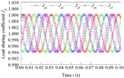
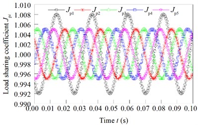
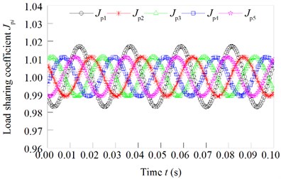
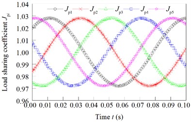
Under these parameters, the load sharing coefficient of the star gears is shown in Fig. 6.
From Fig. 6, we can see that the load sharing coefficient of the star gear is changed according to a certain period. The load sharing coefficients of star gear are 1.023, 1.036, 1.028, 1.030 and 1.025. Therefore, the load sharing coefficient of the system is 1.036.
The torque of first stage star gear and the torque of second stage star gear is changed as shown in Fig. 7(a) and (b).
Fig. 6Effect of the common error of star gear on load sharing coefficient
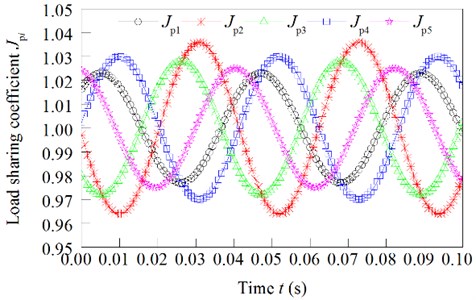
Fig. 7Torque force of the I-stage and II-stage star gears
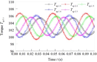
a) Torque of first stage star gear
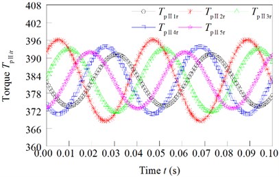
b) Torque of second stage star gear
Fig. 8Load sharing coefficient changed with the eccentricity error independently effect
a) of the sun gear independently effect
b) of the I-stage star gear independently effect
c) of the II-stage star gear independently effect
d) of the ring gear independently effect
The calculation results of the load sharing coefficient are shown in Table 2, when the assembly error of the sun gear, the assembly error and the of the star gear and the assembly error of the ring gear independently effect.
Table 2Load sharing coefficient when assembling error independently effect
Load sharing coefficient | (6 μm) | (6 μm) | (6 μm) | (6 μm) |
1.004 | 1.006 | 1.016 | 1.012 | |
0.996 | 0.995 | 0.983 | 1.010 | |
0.997 | 0.994 | 0.992 | 0.991 | |
1.006 | 1.008 | 1.012 | 1.018 | |
1.003 | 1.005 | 1.013 | 0.985 | |
1.006 | 1.008 | 1.016 | 1.018 |
The calculation results of the load sharing coefficient are shown in Fig. 8, when the eccentric error of the sun gear, the eccentric error and the of the star gear and the eccentric error of the ring gear independently effect.
It can be seen from the above calculation results, for manufacturing and installation errors, when the error’s values are the same, the error of the ring gear is the most, and the second stage star gear error is middle, and the error of the sun gear is the least.
4.2. Effect of the error on the load sharing coefficient
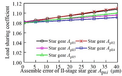
The eccentricity error of the sun gear and the eccentric error of the ring gear affect the load sharing characteristics separately. The relationship between the load sharing coefficient and the error is shown in Fig. 9. The eccentricity error of the I-stage star gear affect the load sharing characteristics separately. The relationship between the load sharing coefficient and the error is shown in Fig. 10. The eccentricity error of the II-stage star gear affect the load sharing characteristics separately. The relationship between the load sharing coefficient and the error is shown in Fig. 11. The assembly error of the sun gear and the eccentric error of the ring gear affect the load sharing characteristics separately. The relationship between the load sharing coefficient and the error is shown in Fig. 12. The assembly error of the I-stage star gear affect the load sharing characteristics separately. The relationship between the load sharing coefficient and the error is shown in Fig. 13. The assembly error of the II-stage star gear affect the load sharing characteristics separately. The relationship between the load sharing coefficient and the error is shown in Fig. 14.
Fig. 9Relationship between eccentricity error of sun gear and ring gear and the load sharing coefficient
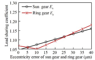
Fig. 10Relationship between eccentricity error of the I-stage star gear and the load sharing coefficient
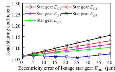
It can be seen from Fig. 9, Fig. 10, and Fig. 11, with the increase of the eccentricity error of the sun gear and the ring gear, the I-stage and II-stage star gear, the load sharing coefficient gradually increases. Gear 4 produces uneven load due to the stiffness of elastic support. However, due to the influence of error, the eccentricity error and the elastic support deformation error will produce a certain amount of superposition. Therefore, when the error varies from 0 to 25 μm, the load-sharing coefficient of the I-grade gear 4 decreases with the increase of the error. When the error is increased again, the load-sharing coefficient increases with the increase of error. In the same way, the load factor of II-grade gear 4 decreases first and then increases.
It can be seen from Fig. 12, Fig. 13, and Fig. 14, with the increase of the assembly error of the sun gear and the ring gear, the I-stage and II-stage star gear, the load sharing coefficient gradually increases. From the above analysis, it can be seen that the load sharing characteristic decreases with the increase of the error. The II-stage error is more than the I-stage error.
Fig. 11Relationship between eccentricity error of the II-stage star gear and the load sharing coefficient
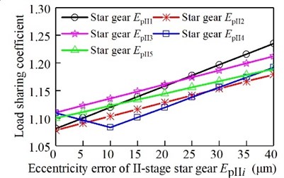
Fig. 12Relationship between assembly error of sun gear and the ring gear and the load sharing coefficient
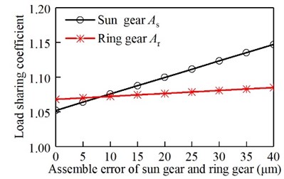
Fig. 13Relationship between the assembly error of the I-stage star gear and the load sharing coefficient
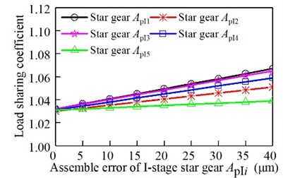
Fig. 14Relationship between the assembly error of the II-stage star gear and the load sharing coefficient
5. Comparison of the impact of the basic components floating
Fig. 15 shows the variation of the load sharing coefficient with the variation of the spline space. From Fig. 15 can be seen under the condition of constant error, the system load sharing coefficient decreases with the increase of spline clearance. When the gap is large enough, the system load sharing characteristics will achieve an ideal load effect. Here, the friction coefficient is 0.1. When the spine clearance is 0.00 mm, the floating sun gear will completely be determined by the bending rigidity of input shaft, here, the sun gear is supported by the elastic support. Next, the spline clearance is gradually increase, the load-sharing characteristics will be better and better. Finally, the load-sharing coefficient is obtained. At the same time, due to the impact of friction, the load sharing coefficient of the system is 1.013.
Fig. 16 shows the variation of the load sharing coefficient.
Fig. 15Load sharing coefficient changed with the effect of spline clearance
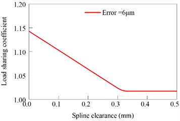
Fig. 16Influence of sun gear and ring floating on the load-sharing characteristic
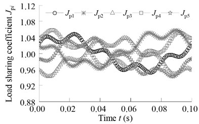
a) Without floating
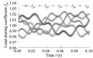
b) Ring gear with floating
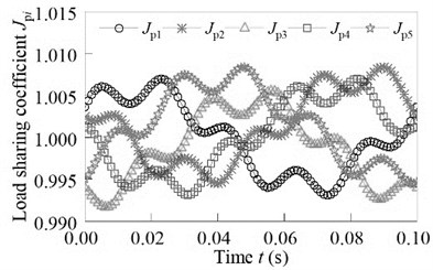
c) Sun gear and ring gear with floating
Fig. 17Floating orbit of the sun gear and ring gear
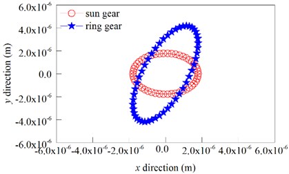
It can be seen from Fig. 16, when the sun gear and ring gear are not floating, the load sharing coefficient is 1.058, and the volatility is large. When the ring gear floating and the sun gear fixed, the load sharing coefficient is 1.023. When the sun gear and ring gear floating, the load sharing coefficient is 1.008. At this time, the system has a good load sharing characteristics, fully meet the system load uniform distribution.
Fig. 17 shows the floating trajectory of the sun gear and ring gear.
6. Experimental verification
In order to verify the correctness of the theoretical analysis of this paper, the static load characteristics test of the two-stage five-branching star gear transmission system is carried out.
In this paper, taking into account the high speed of the star gear transmission is a helical gear, therefore, it can be used to measure the axial force to determine the loaded distribution between the stars of the stars. The five helical gears will produce a certain axial force in the course of the transfer load. The five star gear shafts are transmitted to a special precision mechanical sensor through a torsion bar. The axial force generated by five star gears in high speed operation is measured by a precision mechanical sensor.
The load sharing coefficient of the star gear system can be obtained by the above method. It can evaluate the effect of load sharing characteristics of star gear system. The axial forces of the five helical gears are , , , and , respectively. Therefore, the load sharing coefficient of the star gear system can be obtained by:
Here, is the maximum axial force of three star gears.
In the test process, according to the actual state of the star gear reducer, the load is divided into five load state, for each load state were measured four times, and take the average value as the load of the load sharing coefficient.
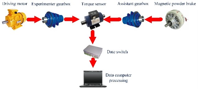
The test piece is installed in the reducer in the tester. The measuring equipment uses the closed principle of mechanical power flow. Due to the tester for closed loop transmission ratio is equal to 1, in order to fulfill these requirements, input terminal of two star gear deceleration device is connected. Along the direction of the power flow, one of the reducer is the role of the increasing speed, the other is the role of the decreasing speed. Fig. 18 is a schematic diagram of the experimental principle. As the picture of experimental process involves military secret project, here, it does not list the experimental scene pictures.
From Fig. 18 it can be seen that the whole test stand is made up of five parts: power source, the main gear box, the measuring system, the test gear box. Here, the motor is powered and controlled by frequency converter speed, gear box is a star gear box. Measurement system including two torque sensor and a display instrument. Paternity testing gear box is another star gear box. load provided by a magnetic powder brake. When the test rig is installed and the coaxial degree of the system is debugged, the system load characteristics test can be carried out. First, the system is energized, and the system is adjusted to zero in the static state. After the completion of the adjustment zero, it adjusts the output frequency of the motor and the load torque. At this time, the load sharing characteristic test is carried out.
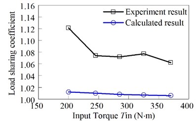
The comparison between theoretical calculation and experimental results is shown in Fig. 19.
It can be seen from Fig. 19 that the experimental data is more than the theoretical calculation value 15 %. Test load sharing coefficient is 1.121, 1.074, 1.072, 1.077 and 1.062, Under the condition of the output torque of 200 N·m, 245 N·m, 285 N·m, 325 N·m, and 370 N·m. Theoretical calculation load sharing coefficient is 1.012, 1.010, 1.008, 1.007 and 1.006. The load sharing coefficient of theoretical calculation decreases with the increase of torque. The overall trend of the average load coefficient of the experiment decreases with the increase of torque, but there is a slight increase in the torque from 285 N·m to 385 N·m, which is caused by the error of the experimental environment. Moreover, the process of theoretical calculation is an ideal condition. Due to the influence of processing, assembly and material heat treatment, the actual situation is different from the theory. In addition, there are errors in the test system, so there are differences between the experimental values and the calculated values. However, the experimental results satisfy the load sharing coefficient of the general engineering recommendation for the range of 1.1-1.5. The correctness of theoretical calculation is verified.
Fig. 18Schematic diagram of the experimental principle
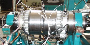
a) Experimental apparatus
b) Experimental flow chart
Fig. 19Schematic diagram of the experimental principle
7. Conclusions
1) The solution of the large complex gear transmission system is simplified by the deformation coordination condition. The errors of various components in the deformation coordination condition can be superimposed or offset. The deformation coordination condition can be applied in the gear transmission system with the power split closed loop characteristics.
2) The eccentric error and the installation error of the various components have an effect on the load characteristics of the system. Moreover, the effects of errors are cumulative, and the error distribution of the components in the II-stage should be paid more attention. The main cause of the unbalanced load distribution of the star gear transmission system is the inconsistent of the manufacturing error and the installation error.
3) The floating of basic components is beneficial to the load sharing among the stars. The spline space is a mechanism to reduce the block effect of floating of the basic components. However, the design of the gap is not the bigger the better, because of the large gap will make the star gear system in the work process to produce serious vibration and impact.
4) Load sharing test was carried out under different loads. The experimental data were processed and the experimental data were consistent with the theoretical calculation data. The correctness of theoretical analysis was verified.
References
-
Mo S., Zhang Y. D., Wu Q. Research on multiple-split load sharing of two-stage star gearing system in consideration of displacement compatibility. Mechanism and Machine Theory, Vol. 88, 2015, p. 1-15.
-
Du J. F., Fang Z. D., Wang B. B., Dong H. Study on load sharing behavior of planetary train based on deformation compatibility. Journal of Aerospace Power, Vol. 27, Issue 5, 2012, p. 1166-1171.
-
Dong H., Fang Z. D., Wang B. B. Load sharing characteristics analysis of power split system based on deflection compatibility and clearance floating. Journal of Aerospace Power, Vol. 28, 2013, p. 872-877.
-
Dong H., Duan L. L. Load-sharing characteristics of power-split transmission system based on deformation compatibility and loaded tooth contact analysis. International Journal of Aerospace Engineering, Vol. 22, 2015, p. 10-24.
-
Guo Y. Planetary gear load sharing of wind turbine drivetrains subjected to non-torque loads. Wind Energy, Vol. 18, 2015, p. 757-768.
-
Park Y. J. Load sharing and distributed on the gear flank of wind turbine planetary gearbox. Journal of Mechanical Science and Technology, Vol. 29, 2015, p. 309-316.
-
Sekar R. P., Muthuveerappan G. Load sharing based maximum fillet stress analysis of asymmetric helical gears designed through direct design – a parametric study. Mechanism and Machine Theory, Vol. 80, 2014, p. 84-102.
-
Sun W. A study on load-sharing structure of multi-stage planetary transmission system. Journal of Mechanical Science and Technology, Vol.29, 2015, p. 1501-1511.
-
Yu H. Sharing behavior of load transmission on gear pair systems actuated by parallel arrangements of multiple pinions. Mechanism and Machine Theory, Vol. 65, 2013, p. 58-70.
-
Montestruc A. N. P. E. A numerical approach to calculation of load sharing in planetary gear drives. Journal of Mechanical Design, Vol. 132, 2010, p. 12-26.
-
Singh A. Load sharing behavior in epicyclic gears: physical explanation and generalized formulation. Mechanism and Machine Theory, Vol. 45, 2010, p. 511-530.
-
Soojin, Suk Y. W. Tooth load sharing and deformation overlap of helical gear pairs for the manual transmission of automobile. Transactions of KSAE, Vol. 11, 2003, p. 190-196.
-
Gill Jeong C., Parker R. G. Influence of bearing stiffness on the static properties of a planetary gear system with manufacturing errors. Journal of Mechanical Science and Technology, Vol. 18, 2004, p. 1978-1988.
-
Ashraf M. M. Peak load sharing based on blade pitch control of wind turbine in the presence of utility supply. Journal of Renewable and Sustainable Energy, Vol. 6, 2014, p. 45-55.
-
Boguski B. A New method to measure planet load sharing and sun gear radial orbit of planetary gear sets. Journal of Mechanical Design, Vol. 134, 2012, p. 1302-1333.
-
Gu X., Velex P. A dynamic model to study the influence of planet position errors in planetary gears. Journal of Sound and Vibration, Vol. 331, 2012, p. 4554-4574.
-
Kim J. K. Effects of bearing internal clearance on the load distribution and load sharing in the pitch reducer for wind turbines. Journal of Manufacturing Engineering and Technology, Vol. 22, 2013, p. 29-35.
-
Wei J. Dynamic analysis and load-sharing characteristic of multiple pinion drives in tunnel boring machine. Journal of Mechanical Science and Technology, Vol. 27, 2013, p. 1385-1392.
-
Li S., Zhang Z., Dong J. Load sharing characteristics of multi-stage planetary gear train using analytical and finite element model. International Journal of Computer Applications in Technology, Vol. 53, Issue 2, 2016, p. 107.
-
Wang Y., Liu C., Liao Y. Electromechanical dynamic simulation and experiment for multi-stage gear transmission system with planetary gears. Cluster Computing, Vol. 5, 2018, p. 1-11.
-
Zhang X., Tang X., Yang W. Analysis of transmission error and load distribution of a hoist two-stage planetary gear system. Proceedings of the Institution of Mechanical Engineers Part K Journal of Multi-body Dynamics, 2018, https://doi.org/10.1177/1464419318770886.
-
Sun W., Li X., Wei J. A study on load-sharing structure of multi-stage planetary transmission system. Journal of Mechanical Science and Technology, Vol. 29, Issue 4, 2015, p. 1501-1511.
-
Iglesias M., del Rincon Fernandez A., de-Juan A. Planetary transmission load sharing: Manufacturing errors and system configuration study. Mechanism and Machine Theory, Vol. 111, 2017, p. 21-38.
-
Li M., Xie L. Y., Ding L. J. Load sharing analysis and reliability prediction for planetary gear train of helicopter. Mechanism and Machine Theory, Vol. 115, 2017, p. 97-113.
-
Jones R., et al. Gear meshing analysis of planetary gear sets with a floating sun gear. Mechanism and Machine Theory, Vol. 84, 2015, p. 145-163.
-
Mo S., Zhang Y. D., Wu Q. Load sharing behavior analysis method of wind turbine gearbox in consideration of multiple-errors. Renewable Energy, Vol. 97, 2015, p. 481-491.
-
Tang X. Planetary gear sets power loss modeling: application to wind turbines. Tribology International, Vol. 105, 2017, p. 42-54.
-
Lei P., Zhu R., Jin G. Load sharing characteristics of single-input gear split torque transmission based on synchronous angle. Journal of Central South University, Vol. 48, 2017, p. 47-53.
Cited by
About this article

National Natural Science Foundation of China (51705390). Supported by the Natural Science Foundation of Shaanxi Provincial (2018JQ5029). Xi’an Science and Technology Plan Project 2017075CG/RC038 (XAGY008). Xi’an Technological University research and innovation team construction program.
