Abstract
Owing to significant influences of in-wheel motors on the performance of suspension, a modified GPSO-LQG controller is proposed for one-quarter vehicle suspension with the purpose of optimizing suspension performance for entire speed ranges. After the introduction of one-quarter vehicle suspension model, road surface excitation model and magneto-rheological damper model, the GPSO-LQG controller is investigated with three weighted coefficients optimized by utilizing the Genetic Particle Swarm Optimization (GPSO). With the intension of meeting the requirements across the speed range, the weighted coefficients are presented as functions of speed in a modified GPSO-LQG controller while constraint values are given in the optimization of the weighted coefficients. Subsequently, simulation models are constructed with two working conditions. In the end, simulation results indicate that the modified GPSO-LQG controller reduces body acceleration by 8.37 % at a low speed and decreases the tire dynamic load by 8.55 % at a high speed, as compared with a GPSO-LQG controller. In terms of its outstanding advantages in improving the performance of suspension, the modified GPSO-LQG controller is more suitable for in-wheel motors suspension.
1. Introduction
Due to their outstanding advantages in emission, electric vehicles are regarded as the solution to deal with the environment pollution and energy dilemma [1]. By replacing the mechanical transmission system, the application of in-wheel motors both saves space and significantly improves the transmission efficiency for various driving modes [2, 3]. In addition, the application of in-wheel motors provides opportunities to improve the dynamic control performance when combined with a four-wheel drive, antilock brake system, etc. Nevertheless, the increase of unsprung mass deteriorates riding comfort and handling stability [4, 5]. Especially, the tire dynamic load will increase at a high speed.
Multiple researches have been carried out studies to improve the performance of in-wheel motors suspension. A high-torque-density permanent-magnet free motor is proposed due to its high efficiency and specific torque [6]. Ma Y. designed a kind of motor installation method to eliminate the vehicle’s negative vertical influence due to the rigid connection between the motor and the wheel [7]. Liu M. proposed an in-wheel vibration model, composed of a spring, annular rubber bushing, and a controllable damper to restrain wheel and motor vibration [8]. In addition to the optimization of the motor structure and installation mode, the optimal design of suspension structure has a better effect. Particularly, the semi-active suspension, matched with the optimal control force, is able to improve riding comfort and handling stability significantly [9]. Combined the advantages of skyhook and power-driven-damper, a new sprung mass control algorithm named as the mixed SH and PDD is proposed, what is effective in reducing the sprung mass vibration across the whole frequency spectrum [10]. Panos Brezas designed a clipped-optimal control algorithm which maintained satisfying state estimation during handling maneuvers [11]. A H2 controller was introduced in terms of the quadratic Lyapunov stability theory and made by means of Linear Matrix Inequalities [12]. A new hardware combination for active suspension systems is presented to improve satisfying conditions, achieved by an iterative optimization procedure for the damping ratio and the weights of time-invariant LQR controllers for active quarter-car models [13]. A skyhook sliding mode system controller is used to gain the desired damping force, and the semi-active controller can achieve compatible performance as that of the active suspension controller except with a little deterioration [14].
Unfortunately, most of the suspension control methods are designed for general vehicles and focus on optimizing riding comfort, merely for vehicles with increased unsprung mass or for in-wheel motors suspension [15], whose control method for in-wheel motors suspension must pay more attention to the tire load and improve the vehicle stability. Furthermore, requirements for suspension across the entire speed range are always ignored, while the high-speed handling stability is of vital importance for in-wheel motors suspension.
Therefore, it is significant to design a controller with the requirements of in-wheel motors suspension. In this paper, the GPSO is employed to develop an LQG controller, concentrated on the increase of unsprung mass [16-18]. In order to satisfy the requirements across the speed range, the weighted coefficients of body acceleration, suspension working space and tire dynamic load are presented as speed functions to match the optimal control force.
In summary, the contributions of this paper are listed as follows:
1. Overcoming the limitation of traditional semi-active suspension design, a semi-active control strategy is designed to meet the requirements of in-wheel motor suspension.
2. The semi-active control strategy is optimized by combining the advantage of genetic algorithm and the particle swarm optimization algorithm.
3. According to the performance requirements at different speeds, the speed adaptive control is carried out. The control strategy selects different optimization targets at different speeds and sets the corresponding constraint conditions by defining the value of , .
4. The magneto-rheological shock absorber is used to provide optimal control force.
This paper is organized as follows. The next section presents the modeling of one-quarter vehicle suspension and road excitation. Then, Section 3 provides the introduction of magneto-rheological damper. Next, Section 4 provides the GPSO-LQG controller used in this paper. The differences between controllers are presented in Section 5. The speed adaptive control is detailed in Section 6, whereas the conclusions are given in Section 7.
2. Modeling of one-quarter vehicle suspension and road excitation
2.1. Dynamic model of one-quarter vehicle suspension
A dynamic model of one-quarter vehicle suspension is used in this paper as shown in Fig. 1.
Fig. 1Dynamic model of one-quarter vehicle suspension
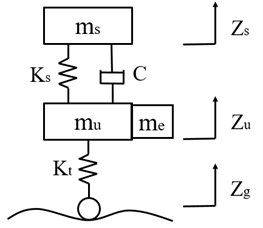
a) Passive suspension
b) Semi-active suspension
Based on the Newtonian second law, the differential dynamics equations for semi-active suspension systems are expressed as Eq. (1):
where , , denote the sprung mass, unsprung mass and motor mass, , , are the displacements of body, wheel and road, respectively: , stand for the stiffness of spring and tire, respectively: represents the control force; indicates the damping.
2.2. Road surface excitation model
Random white Gaussian noise is selected as the source waveform of suspension, and the mathematic formula of road surface excitation model is expressed as follows:
Here, is the lower cut of frequency and equals to 0.011·; is the road roughness coefficient, indicates the speed of vehicles, denotes a random white Gaussian noise which variance is 1.
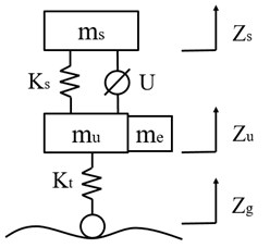
As the C-level road is defined, and the speed is set to 50 km/h herein, the vertical displacement of the tire is shown in Fig. 2.
Fig. 2Road surface excitation model
3. Model of magneto-rheological damper
Magneto-rheological damper is a kind of shock absorber based on the controllable characteristic of the magneto-rheological fluid in the magnetic field. It has the characteristics such as wide adjustment range, fast response speed, high temperature adaptability and adjustable damping [19]. For the purpose of ensuring the stability of control process and maximizing the vibration capacity of the magneto-rheological damper, it is essential to establish a precise mechanical model to capture the inherent hysteresis behavior of the magneto-rheological damper. However, due to the strong nonlinear hysteresis characteristics of magneto-rheological damper, there is no widely accepted mechanical model. Most commonly used models include the Bingham model [20], Bouc-Wen model [21], Spencer Phenomenological model [22], polynomial model and neural network model [23], etc.
For the sake of high fitting accuracy, the polynomial model is used in this article. The hysteresis loop of the damping force is divided into two parts: lower loop with positive acceleration and upper loop with negative acceleration [24]. Then the hysteresis loop is fitted by the polynomial. Therefore, the damping force is expressed as:
where is the damping force, , are the fitting coefficients of the hysteresis loop, is the velocity of piston.
Owing to the nonlinear relationship between fitting coefficient and the control current [25], the modified relationship model between and is expressed as:
where , , are the damping force coefficients of the lower loop, , , are the damping force coefficients of the lower loop, 0, 1, 2, …, .
According to the “QC-T 545-1999 automobile cylinder shock absorber bench test method”, the mechanical properties tests of magneto-rheological damper are carried out. The excitation frequency and magnitude are chosen as 0.17 Hz, 0.42 Hz, 0.87 Hz, 1.67 Hz and ±25 mm respectively, while the current is set as 0 A, 0.5 A, 1 A, 1.5 A, 2 A. Then the relationship curves of the damping force-piston velocity (force characteristics) are obtained through the mechanical properties tests.
Fig. 3Magneto-rheological damper

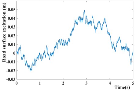
For the sake of the computational time and fitting accuracy, a sixth order polynomial is chosen, that means including , , , , , , and including , , , , , , In the case of 25 mm and 1.67 Hz, the hysteresis loops of damping force are fitted by the Cf tool of Matlab. The fitting results are shown in Fig. 4.
It can be seen from Fig. 4 that the polynomial model of magneto-rheological damper is able to simulate the experimental data accurately, according to the fitting curve.
Fig. 4Force characteristics of Magneto-rheological damper
4. Semi-active suspension controller
4.1. Design of LQG controller
The main performances of one-quarter vehicle contain the body acceleration (BA), suspension working space (SWS) and tire dynamic load (TDL). Hence, the state variable is selected as .
Based on the one-quarter vehicle model and road surface excitation model, the state-space equation is described as Eq. (5):
where denotes the input matrix of control force, is the input matrix of white Gaussian noise:
During the optimization of suspension, the main performance indicators usually include the following three aspects: 1) tire dynamic load that represents the handling stability; 2) body acceleration that represents the riding comfort; 3) suspension working space that influence the body posture and is related to the structural design and layout. In order to quantify these three performance indicators, a root-mean-square value is utilized and represents the overall level at all frequencies. With the purpose of improving riding comfort and handling stability, the performance is evaluated by which is derived as follows:
where , , are the weighted coefficients of body acceleration, suspension working space and tire dynamic load.
Eq. (7) is rewritten by the integral quadratic function shown as follows:
where:
The feedback gain matrix is calculated by solving the following Riccati equation, after determining the vehicle parameters and weighted coefficients:
The feedback gain matrix is determined by vehicle parameters and weighted coefficients. The solution to the optimal control problem is the state feedback law.
According to the model of magneto-rheological damper, it provides the damping force within a certain range varying with the velocity of the piston, that means there are upper and lower limits at each velocity. Therefore, the magneto-rheological damper cannot always produce the damping force which is equal to the feedback gain matrix. Owing to dynamic peculiarity of magneto-rheological damper, the optimal control force is derived as follows:
where is the velocity of piston; , stand for the upper and lower limits of damping force at a certain velocity.
4.2. Genetic particle swarm optimization
From the above inference, the feedback gain matrix is relied on weighted coefficients while the parameters of vehicles are determined. In order to weaken the adverse effect caused by empirical selection, the optimizing LQG controller by optimum algorithms is taken into consideration. A number of optimum algorithms have been used to improve the controlling accuracy, as Artificial Bee Colony (ABC) [26], Analytic Hierarchy Process (AHP) [27, 28], Fruit Fly Optimization Algorithm (FOA) [29], Genetic Algorithm (GA) [30], and Particle Swarm Optimization (PSO).
Both the Genetic Algorithm (GA) and Particle Swarm Optimization (PSO) are searched from multiple points and have an excellent searching ability. Although the Genetic Algorithm has good convergence, but due to its poor local search ability, the simple genetic algorithm is very time consuming, and it is easy to induce the premature convergence condition in the late population evolution. On the other hand, GA has unique operations, such as selection, crossover and mutation, to increase the diversity of population and improve the reliability of the optimization process. Compared with GA, the PSO both has the excellent optimization ability, and runs faster. The individual of PSO has a good memory, which is suitable for solving complex optimization problems.
Combining the advantage of Genetic Algorithm and Particle Swarm Optimization, the Genetic Particle Swarm Optimization (GPSO) is applied to provide the higher reliability and faster convergence. A flow chart of GPSO is presented in Fig. 5.
Fig. 5GPSO flow chart
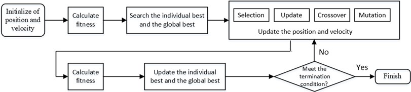
When the basic principle of GPSO has been introduced in the above flow chart, the methods to update position and velocity of the particles in the search space are determined by the following steps.
Step 1: good individuals are selected from the old group with certain probability to form a new population.
The probability of an individual being selected can be expressed by the following expression:
where is the fitness of individual ; is the population number.
Step 2: Updating position and velocity of the particles by the method of PSO using the following expression:
where is the position of particle; is the vehicle of particle; stands for the Inertial factor; stand for the acceleration constants; , stand for random numbers between 0 and 1; denotes the best position of individual; denotes the best global position.
Step 3: Two individuals are randomly selected from the population, crossed with the crossover probability , and the operation to crossover the th feature of the th individual and th individual is shown as follows:
where is a random number between 0 and 1.
Step 4: The individuals are randomly selected from the population with probability , and produce better individuals by mutation:
where is the th feature of the i-th individual; and denote the bounds of ; , is a random number between 0 and 1, means Current iteration times, is the maximum number of iterations.
Fig. 6GPSO-LQG controller flow chart
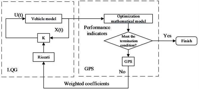
Following the GPSO flow chart and the GPSO-LQG controller flow chart, the steps to develop GPSO-LQG controller are given as follows [31, 32]:
Step 1: Determining the initial value of three weighted coefficients (, , ).
Step 2: Evaluating the suspension performance which is represented by fitting the function .
Step 3: Generating new weighted coefficients based on the suspension performance of individual best and group best.
Step 4: Evaluating the suspension performance with new weighted coefficients.
Step 5: If the iteration stop condition is met, the global optimal solution is obtained, otherwise return to the Step 3.
4.3. Optimization model of GPSO-LQG
4.3.1. Optimization variables
The weighted coefficients of GPSO-LQG controller for a one-quarter vehicle suspension model mainly include , , on behalf of body acceleration, suspension working space and tire dynamic load. The weight coefficients represent the importance of performance indicators in suspension control. Thus, the optimization variables are proposed as follows:
4.3.2. Fitness function
The main purpose of optimizing the weighted coefficients is to improve the suspension performance. Therefore, the fitness function of GPSO-LQG is designed based on the root-mean-square values of suspension performance including body acceleration, suspension working space and tire dynamic load.
The fitness function and constraint conditions are given as follows:
where represents the root-mean-square value, stands for the performance of semi-active suspension, stands for the performance of passive suspension.
Based on the optimization variables and fitness function, the optimization model of GPSO-LQG controller is:
5. Simulation and analysis
The model parameters, derived from the mini car (LITE developed by BAIC BJEV), are shown in Table 1.
According to the above parameters and the analysis of vehicles, magneto-rheological shock absorbers and LQG controllers, a simulation model was built in Simulink, as shown in Fig. 7.
Reasonable number of population and iteration plays an important part in the optimization effect. Furthermore, , , represent the significance of three performance values, and the performance values do not have the same magnitude. Therefore, the calculation precision and optimization degree will be influenced while the same ranges of position and speed are chosen for weighted coefficients. According to the root-mean-square value of the suspension performance indicators, the weighted coefficients are normalized as shown in Table 2.
Fig. 7Simulation model in Simulink
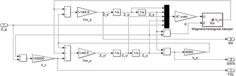
Table 1Model parameters of one-quarter vehicle suspension
Parameter | Value |
Sprung mass | 185 kg |
Unsprung mass | 40.5 kg |
Spring stiffness | 8813 N/m |
Damping | 765 Ns/m |
Tire stiffness | 125000 N/m |
Table 2Optimization parameters of GPSO
Parameter | Value |
Number of population | 50 |
Inertia | 0.6 |
Correction factors | 2 |
Correction factors | 2 |
Number of Iterations | 50 |
Crossover probability | 0.6 |
Mutation probability | 0.05 |
Position range of | [0.1 10] |
Position range of | [1 10000] |
Position range of | [10000 150000] |
Speed range of | [–0.5 0.5] |
Speed range of | [–500 500] |
Speed range of | [–7000 7000] |
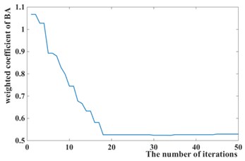
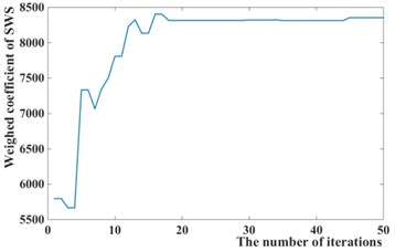
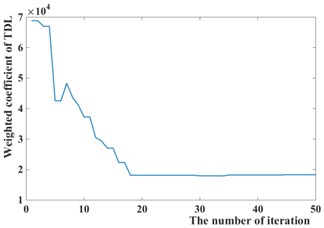
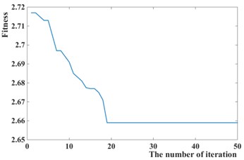
The weighted coefficients optimized by the Particles Swarm Optimization is 0.5294, 8354.8, 18318, as shown in Fig. 8, while 1, 10000, 30000 is chosen by experience. The simulation of passive suspension, semi-active suspension with LQG controller and semi-active with GPSO-LQG controller is carried out, and the same road excitation is selected for it. The time domain responses of suspension performance are shown in Fig. 9, and the power spectral density is shown in Fig. 10.
Compared with the passive suspension, the semi-active suspension with LQG controller or GPSO-LQG controller reduces the power spectral density of body acceleration and dynamic load at a resonant frequency of body, obviously. In particular, the LQG controller has the most outstanding performance in reducing the body vibration, while the root-mean-square value of body acceleration decreases by 12.7 %, and the peak reduces to 2.85 m/s2 compared with 3.29 m/s2 for passive suspension. Although the LQG control increases the riding comfort by reducing the body acceleration while tire dynamic load increasing to 472.5 N, the simulation results provide the evidence that the semi-active suspension with LQG controller fails to decrease the tire dynamic load and is incapable of fitting the requirements of in-wheel motors suspension.
Fig. 8Iteration process curves of GPSO
a)
b)
c)
d)
Fig. 9Time domain responses of suspension performance of different models
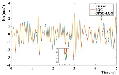
a) Body acceleration of different models
b) Suspension working space of different models
c) Tire dynamic load of different models
Fig. 10PSD of suspension performance indicators of different models
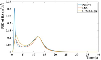
a) PSD of body acceleration
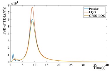
b) PSD of tire dynamic load
Table 3The root-mean-square value of the suspension performance and the degree of optimization
BA / (m/s2) | SWS / m | TDL / N | ||||
RMS | Degree of optimization | RMS | Degree of optimization | RMS | Degree of optimization | |
Passive | 0.9582 | – | 0.008216 | – | 470.5 | – |
LQG | 0.8371 | 12.7 % | 0.006646 | 19.1 % | 472.5 | –0.4 % |
GPSO-LQG | 0.9058 | 5.5 % | 0.006269 | 23.7 % | 446.6 | 5.1 % |
In contrast, the GPSO-LQG controller is weaker than the LQG controller in reducing the body acceleration, and the root-mean-square value of body acceleration only decreases by 5.5 %, However the GPSO-LQG controller has the ability to reduce both the body acceleration and tire dynamic load at the same time to ensure the riding comfort and handling stability, as the RMS of tire dynamic load decreasing to 446.6 N. Furthermore, in-wheel motors increase the unsprung mass significantly, so the optimization design requires more attention to decrease the tire dynamic load and to improve the handling stability. According to Fig. 9(c) and Fig. 10(b), the GPSO-LQG controller both reduces the peak of tire dynamic load at a C-level road with the speed of 50 km/h, and demonstrates good performance in minishing the PSD of tire dynamic load at a resonance frequency of tire. In general, GPSO-LQG is more reasonable for in-wheel motor suspension performance optimization.
6. Modified GPSO-LQG controller
According to the previous analysis, the tire dynamic load optimization is the biggest challenge of in-wheel motors suspension while the optimization of common suspension only uses the tire dynamic load as the constraint condition, not as the optimization target. It is proved that the GPSO-LQG controller has more advantages in reducing the tire dynamic load than LQG controller. However, the optimization effect of the GPSO-LQG controller on handling stability is not very significant, the tire dynamic load only decreased by 5.10 %. Due to the control effect, the GPSO-LQG controller fails to meet the requirement of handling stability while more attention is demanded at a high speed. Hence, a modified GPSO-LQG controller, with weighed coefficients designed as the functions of speed, is proposed in this paper.
An appropriate controller for in-wheel motor suspension is required to guarantee the stability at a high speed and ensure the low-speed riding comfort. Therefore, a modified GPSO-LQG controller improves the weighted coefficient of tire dynamic load as the increasing velocity that means paying more attention to optimize the handling stability. Meanwhile, it causes a deterioration of riding comfort due to the characteristics of LQG. Thus, it is necessary to define an acceptance domain and ensure all suspension performance indexes within this range.
6.1. Optimization model of Modified GPSO-LQG
Modified GPSO-LQG controller has the corresponding design objectives at different speeds, and the optimization model of Modified GPSO-LQG is different at a high speed or a low speed.
The optimization model at a low speed is represented by:
The optimization model at a high speed is described as Eq. (21):
The values of , are shown in Table 4.
Following the optimization model, body acceleration is chosen as the fitness function at a low speed while the tire dynamic load is selected at a high speed. Furthermore, the constraint value proposed in Table 4 defines an acceptable domain. It is required to put forward that the GPSO-LQG controller designed before is utilized at the speed of 50-60 km/h which is commonly used in vehicle driving.
Due to the optimization model of modified GPSO-LQG controller, the suitable weighted coefficients optimized by GPSO at different speeds are described as follows.
Table 4Constraint value at different speeds
Speed | 0-20 | 20-40 | 40-50 | 60-80 | 80-100 | >100 |
1.15 | 1.1 | 1.05 | 1.05 | 1.1 | 1.15 | |
1.1 | 1.05 | 1.05 | 1.1 | 1.05 | 1 |
Table 5Weighted coefficients and feedback gain matrix at different speeds
Speed | ||||||||
0-20 | 3.8312 | 4301.3 | 107200 | 1519.3 | –546.5 | –1845.8 | –209.7 | 2592.8 |
20-40 | 2.8886 | 2177.9 | 108029 | 1383.1 | –623.5 | –2996.2 | –1513.2 | 4911.3 |
40-50 | 2.5057 | 3101.8 | 119594 | 1667.2 | –741.4 | –834.0 | –5567.5 | 6906.2 |
50-60 | 0.5294 | 8354.8 | 18318 | 2852.0 | –686.6 | 15404 | –8133.8 | –5978.5 |
60-80 | 1.4037 | 1867.7 | 138695 | 1829.8 | –977.2 | 189.9 | –13673 | 13936 |
80-100 | 0.8518 | 1696.2 | 101948 | 1967.7 | –1045.2 | 1331.0 | –16890 | 16055 |
>100 | 0.5938 | 94.756 | 90989 | 973.7 | –1202.7 | –5816.8 | –16289 | 21876 |
Fig. 11Road surface excitation for GPSO-LQG and modified GPSO-LQG: a) with low speed and b) with high speed
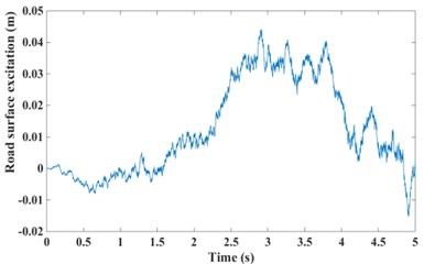
a)
b)
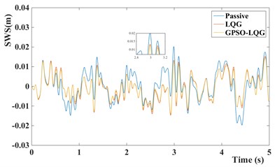
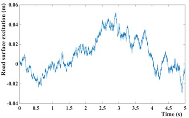
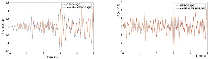
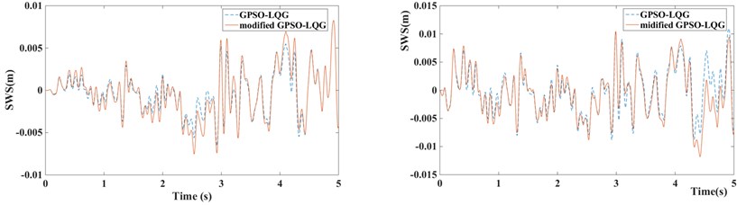
Fig. 12Suspension performance indicators of GPSO-LQG and modified GPSO-LQG (left figure with low speed and right figure with high speed)
a) Body acceleration of GPSO-LQG and modified GPSO-LQG
b) Suspension working space of GPSO-LQG and modified GPSO-LQG
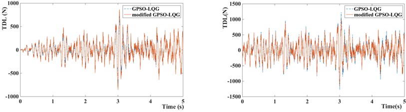
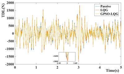
c) Tire dynamic load of GPSO-LQG and modified GPSO-LQG
6.2. Simulation of GPSO-LQG and modified GPSO-LQG
In order to verify the rationality of modified GPSO-LQG controller, two working conditions based on the actual operation of the vehicles are selected for simulation, including driving with a low speed (accelerated from 0 km/h to 60 km/h, and the acceleration time is 5 s) at a C-level road and driving with a high speed (accelerated from 60 km/h to 120 km/h, and the acceleration time is 5 s) at a B-level road to obtain the average level of performance at high and low speeds. The performance of suspension with GPSO-LQG controller and modified GPSO-LQG controller is compared in simulation, with the same road excitation and structure parameters.
Fig. 13Control force of GPSO-LQG and modified GPSO-LQG: a) with low speed and b) with high speed
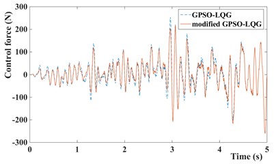
a)
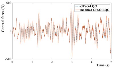
b)
Fig. 14Input current of MR damper of GPSO-LQG and modified GPSO-LQG: a) with low speed and b) with high speed
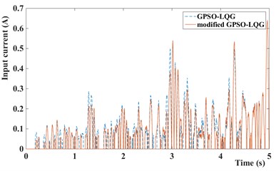
a)
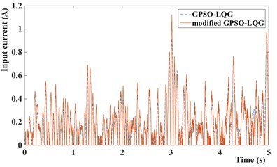
b)
Compared with the standard GPSO-LQG controller, the modified GPSO-LQG controller has an advantage in reducing the body acceleration at a low speed, as the root-mean-square values reduce by 8.37 %, and the RMS of body acceleration decrease to 0.4521 m/s2. This will significantly increase the riding comfort. Although the performance indexes of suspension working space get worse, and the maximum value reaches 19.5 mm, it meets the requirements of structure layout while the design scope of suspension working space is ±80 mm. Due to loose requirements of handling stability at a low speed, the 9.37 % increase of tire dynamic load is acceptable. What’s more, the frequency response from the road disturbance to the tire deformation performs well at a low excitation frequency according to Fig. 16. When vehicles drive at a high speed, the riding comfort gets worse, and the body acceleration increases by 6.23 %.
Table 6Root-mean-square value of suspension performance for GPSO-LQG and modified GPSO-LQG and the degree of optimization
BA / (m/s2) | SWS / m | TDL / N | |||||
Driving with low speed at C-level road | GPSO-LQG | 0.4934 | – | 0.003305 | – | 236.9 | – |
Modified GPSO-LQG | 0.4521 | 8.37 % | 0.003906 | –18.1 % | 259.1 | –9.37 % | |
Driving with high speed at B-level road | GPSO-LQG | 0.8599 | – | 0.005321 | – | 419.7 | – |
Modified GPSO-LQG | 0.9135 | –6.23 % | 0.005725 | –7.59 % | 383.8 | 8.55 % | |
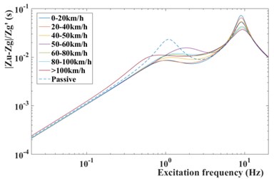
However, as shown in Fig. 15, the frequency response from the road disturbance to the body acceleration of semi-active suspension with modified GPSO-LQG controller performs better than the passive suspension at a low excitation frequency (4 Hz-8 Hz) which is the most sensitive frequency for human. By this way, the riding comfort is controlled within the ideal range. On the other hand, the tire dynamic load reduces by 8.55 %, decreases from 419.7 N to 383.8 N, due to the excellent frequency response at a high excitation frequency proposed by Fig. 16. Therefore, the modified GPSO-LQG improves the riding comfort and is of benefit to improve the high-speed handling stability. This effect improves the ability of adapting to in-wheel motors driven vehicles significantly.
Fig. 15Frequency response from road disturbance z˙q to body acceleration z¨s
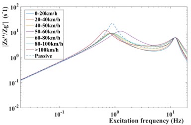
Fig. 16Frequency response from road disturbance z˙q to tire deformation zu-zq
In this paper, the magneto-rheological shock absorber is used to improve the suspension performance, the control force and input current of MR damper are given at Fig. 13 and Fig. 14. Obviously, it can be seen that the control force and input current of suspension with modified GPSO-LQG controller is smaller than suspension with GPSO-LQG controller at low speed, and bigger at high speed. This phenomenon indicates that the suspension is relatively soft at low speeds and hard at high speeds, which meets the requirements of suspension design.
7. Conclusions
Due to the deterioration in handling stability caused by the application of in-wheel motors, the Particle Swarm Optimization is used to match the optimal weighted coefficients of LQG controller. What’s more, a modified GPSO-LQG controller is proposed to fit the requirements at different speeds. With the increase of speed, the modified GPSO-LQG controller focuses more on the tire dynamic load by changing weighed coefficients. The advantage of modified GPSO-LQG controller is verified by simulation at two working conditions, driving with a low speed at a C-level road and driving with a high speed at a B-level road. Simulation results indicate that the modified GPSO-LQG controller is able to improve the high-speed handling stability and the low-speed riding comfort, on the basis of ensuring all suspension performance indexes within the reasonable range. Therefore, it can be concluded that the modified GPSO-LQG controller is more suitable for in-wheel motors suspension applications.
Future work will pay more attention to the design of semi-active suspension control algorithms for full vehicles suspension including pitch and roll motion, and it will verify the control effect in real vehicle tests.
References
-
Sun W., Li Y., Huang J., Zhang N. Vibration effect and control of in-wheel switched reluctance motor for electric vehicle. Journal of Sound and Vibration, Vol. 338, Issue 1, 2015, p. 105-120.
-
Wang R., Jing H., Yan F., et al. Optimization and finite-frequency H∞, control of active suspensions in in-wheel motor driven electric ground vehicles. Journal of the Franklin Institute, Vol. 352, Issue 2, 2015, p. 468-484.
-
Lu C., Tan D., Gang X. Parameter sensitivity analysis of coupling dynamics of in-wheel motor driving electric vehicle. Science Technology and Engineering, Vol. 15, Issue 28, 2015, p. 78-87.
-
Ma Y., Deng Z., Xie D. Control of active suspension for in-wheel moto. Journal of Advanced Mechanical Design Systems and Manufacturing, Vol. 7, Issue 7, 2013, p. 535-543.
-
Luo Y., Tan D. Study on the dynamics of in-wheel motor system. IEEE Transactions on Vehicular Technology, Vol. 61, Issue 8, 2012, p. 3510-3518.
-
Nikam S. P., Rallabandi V., Fernandes B. G. High-torque-density permanent-magnet free motor for in-wheel electric vehicle application. IEEE Transactions on Industry Applications, Vol. 48, Issue 6, 2013, p. 2287-2295.
-
Ma Y., Deng Z., Xie D. Analysis and optimization of in-wheel motor suspension configuration. Journal of Central South University (Science and Technology), Vol. 45, Issue 9, 2014, p. 3008-3014.
-
Liu M., Gu F., Zhang Y. Ride comfort optimization of in-wheel-motor electric vehicles with in-wheel vibration absorbers. Energies, Vol. 10, Issue 10, 2017, p. 1647-1667.
-
Sande T. P. J. V. D., Besselink I. J. M., Nijmeijer H. Rule-based control of semi-active suspension for minimal sprung mass acceleration: design and measurement. Vehicle System Dynamics, Vol. 54, Issue 5, 2016, p. 120.
-
Liu Y., Zuo L. Mixed skyhook and PDD: new low-jerk semi-active suspension control based on power flow analysis. Journal of Dynamic Systems Measurement and Control, Vol. 138, Issue 8, 2016, p. 081009.
-
Brezas P., Smith M. C., Hoult W. Clipped-optimal control algorithm for semi-active vehicle suspensions: theory and experimental evaluation. Automatica, Vol. 53, Issue 1, 2015, p. 188-194.
-
Félixherrán L. C., Mehdi D., Ramírezmendoza R. A., et al. H2 control of one-quarter semi-active ground vehicle suspension. Journal of Applied Research and Technology, Vol. 14, Issue 3, 2016, p. 173-183.
-
Koch G., Fritsch O., Lohmann B. Potential of low bandwidth active suspension control with continuously variable damper. Control Engineering Practice, Vol. 41, Issue 2, 2008, p. 3392-3397.
-
Balamurugan L., Jancirani J., Eltantawie M. A. Generalized magneto-rheological (MR) damper model and its application in semi-active control of vehicle suspension system. International Journal of Automotive Technology, Vol. 15, Issue 3, 2014, p. 419-427.
-
Wang R., Wang J. Fault-tolerant control for electric ground vehicles with independently-actuated in-wheel motors. Dynamic Systems and Control Conference, 2012, p. 194-203.
-
Chen S., Li X., Wang S., et al. PWM Design for active suspension without external energy supply based on LQG control. Applied Mechanics and Materials, Vol. 270, Issue 1, 2013, p. 1478-1481.
-
Chen S., Zu G., Yao M., et al. Taylor series-LQG control for time delay compensation of magneto-rheological semi-active suspension. Journal of Vibration and Shock, Vol. 36, Issue 7, 2017, p. 190-196.
-
Chen S., Zong C. Genetic particle swarm LQG control of vehicle active suspension. Automotive Engineering, Vol. 37, Issue 3, 2015, p. 189-193.
-
Wang G. Research on Control Strategy of Magneto-Rheological Semi-Active Suspension System. Harbin Institute of Technology, 2013.
-
Stanway R., Sproston J. L., Stevens N. G. Non-linear modeling of electro-rheological vibration damper. Journal of Electrostatics, Vol. 20, Issue 2, 1987, p. 167-184.
-
Wen Y. K. Method for random vibration of hysteretic systems. Journal of the Engineering Mechanics Division, Vol. 102, Issue 2, 1976, p. 249-263.
-
Spencer B. F., Dyke S. J., Sain M. K., et al. Phenomenological model for magneto-rheological dampers. Journal of Engineering Mechanics, Vol. 123, Issue 3, 1997, p. 230-238.
-
Chang C. C., Roschke P. Neural network modeling of magneto-rheological damper. Journal of Intelligent Material Systems and Structures, Vol. 9, Issue 9, 1998, p. 755-764.
-
Choi S. B., Lee S. K., Park Y. P. Hysteresis model for field-dependent damping force of magneto-rheological damper. Journal of Sound and Vibration, Vol. 245, Issue 5, 2001, p. 375-383.
-
Kou F. Design and test of vehicle semi-active suspension with magneto-rheological damper. Transactions of the Chinese Society for Agricultural Machinery, 2016.
-
Wang W., Jing Y., Yang L., et al. Weight optimization for LQG controller based on artificial bee colony algorithm. AASRI Procedia, Vol. 3 Issue 1, 2012, p. 686-693.
-
Them A. Design of LQG controller for active suspension based on analytic hierarchy process. Mathematical Problems in Engineering, Vol. 2010, Issue 1, 2010, p. 242-256.
-
Li J. H., He J., Li X. H. LQG controller design for heavy vehicle active suspension based on OT-AHP Method. Applied Mechanics and Materials, Vol. 509, Issue 1, 2014, p. 206-212.
-
Xiao P., Gao H., Lou J., et al. Research on Suspension with novel dampers based on developed FOA-LQG control algorithm. Mathematical Problems in Engineering, Vol. 3, Issue 2017, 2017, p. 112.
-
Chen S., Zhou H., Liu H., et al. Optimal design of active suspension based on LQG control without road input signal. International Conference on Intelligent Computation Technology and Automation, 2011, p. 456-459.
-
Mahmoud M. S., Rahman M. S. U. Event triggered of microgrid control with communication and control optimization. Journal of the Franklin Institute, Vol. 353, Issue 16, 2016, p. 4114-4132.
-
Li B., Sinha U., Sankaranarayanan G. Modeling and control of non-linear tissue compression and heating using LQG controller for automation in robotic surgery. Transactions of the Institute of Measurement and Control, Vol. 38, Issue 12, 2015, p. 1491-1499.
Cited by
About this article

This work was partially supported by the National Key R&D Program of China (No. 2017YFB0103600) and the National Key R&D Program of China (2017YFC0601604).
