Abstract
A synchronization method of pneumatic actuators operating in autovibration mode and fed by pulsatile pressure has been investigated. A mathematical model was analysed numerically describing the dynamics of two vibroexciters connected through aerodynamic channel. The effect of parameters of pulsatile feed pressure on shapes of vibrations of vibroexciter’s working body has been determined. Values of geometrical and dynamical parameters at which synchronization of the mechanical system takes place have been determined. In this case, actuator’s movement law can be both harmonic and non-harmonic in case of pulsating amplitude.
1. Introduction
Mechanical system with two pneumatic vibroexciters of single freedom degree operating in autovibration mode has been researched in this paper. In case of several vibroxciters, it is often important to reach their synchronous operating mode. K. Ragulskis, the author of combined spontaneous synchronization method, and his students have created new principles of stabilization of vibrating systems and have developed the related theory [1]. A vibratory synchronization transmission of two exciters has been investigated in the paper [2]. In paper [3] authors have analyzed synchronization of two exciters which stems from the load coupling that produces the torque of general dynamic symmetry to force the phase difference between the two exciters close to the angle of general dynamic symmetry. This paper is related with the researches described in work [4]. This paper is further continuing the research of synchronization of vibroexciters, using synchronizing aerodynamic link between chambers and feeding pulsatile pressure to the chambers.
The aim of the paper is to apply the mathematical model of synchronization of two pneumatic vibroexciters presented in the paper [4] to the case of pulsatile pressure and study numerically operating modes of vibroexciters, determine dependency of amplitude and frequency versus pulsatile feed pressure, and evaluate the effect of synchronizing channel on parameters of vibrations of vibroexciters in case of different geometrical and dynamical parameters of the mechanical system, comparing to the previous works of the authors of this paper.
2. Mathematical model of mechanical system
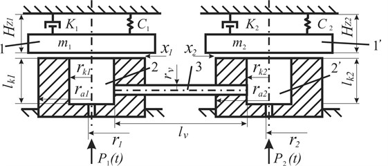
A research of two vibroexciters connected with aerodynamic link is analyzed in this paper. Aerodynamic link has shape of tube (radius , length ). The principle scheme of mechanical system is shown in Fig. 1.
Like in work [4], the mechanical system is described by two differential equations of second order that describe the movement of working body (masses and ) of each vibroexciter:
where – initial tightening of vibrating masses that cause the rigidity of all system, – pressure of pressed air in chambers, – atmospheric pressure, – coefficient of resistance, – coefficient of rigidity, – amplitude of vibrations of chambers working body, where 1, 2.
Fig. 1Scheme of self-synchronization of pneumatic vibroexciters: 1, 1’ – oscillatory mass, 2, 2’ – chamber of vibrodrive, 3 – tube link, P1, P2 – supplied gas pressure, r1, r2 – radius of the air supply channel, rk1, rk2 – chamber radius, lk1, lk2 – chamber height, ra1, ra2 – external radius, lv – length of the linking channel, rv – radius of the linking channel
The mass of gases in chambers is described by the law of gas mass balance:
where – mass of gases in chambers, – amount of feeding air, – amount of air outflowing from chamber in direction of working body, – amount of gases outflowing (feeding in) from chamber through synchronization channel. In general, the mass of gases in chambers is calculated:
Defining the flow of gas inside the camera is based on the theory described in the work [4] and the De Saint Venant and Vantzel equations are given in work [5].
The pressure which are fed to the chambers of vibroexciters pulsate by the law:
where – pressed air pressures and pulsating about the position of equilibrium with pulsation amplitude , angular frequency and initial phase .
The dynamics of two vibroexciters connected with aerodynamic link of synchronization channel could be described by system of Eq. (1-5), where expressions are presented in previous authors’ works.
During the solution process, the system of the first and second degree differential equations is transformed into a system with eight equations of the first degree. To solve these equations, the Runge-Kutta method was applied based on a fixed number of integration steps. The solution was realized using MathCad software.
3. Results of theoretical research
The geometric parameters (, , , , , ) of the chambers, the values of the initial adjuster Hz and masses and of the working body were fixed during the theoretical research presented in this paper. Some characteristics of pulsatile pressure according to the Eq. (5) have been changed: angular frequencies , and initial phases ,. Initial testing data for all tests are listed in Table 1. The vibrations without aerodynamic connection of the working bodies of the vibroexciters were initially investigated, i.e., the vibroexciters were working independently (without a synchronization channel). After that the effect of introduction of synchronizing channel to the autovibrations character has been observed.
Table 1Initial testing data
, kg | , ×10-3 m | , ×10-3 m | , ×10-3 m | , ×10-3 m | , kg/s | , N/m | , ×10-3 m | , ×10-3 m | , ×10-3 m | |
1 | 1.48 | 20 | 55 | 28 | 3.1 | 20 | 3480 | 4.0 | 100 | 2.5 |
2 | 1.4 | 25 | 60 | 35 | 2 | 20 | 5900 | 2.0 |
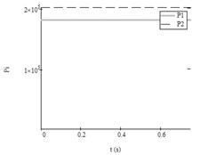
The data of pulsatile pressure and the parameters of autovibrations with the links to the figures without synchronizing channel and after the activation of synchronizing channel are shown in Table 2. The 1st column – number of the test, 2nd – number of vibroexciter, 3rd-6th – initial settings of feeding pressure, 7th-8th – parameters of autovibrations without synchronization channel, 10th-11th - parameters of autovibrations with aerodynamic link and 9th,12th – numbers of figures that illustrate these vibrations. The pulsating amplitude is referred as var.
Table 2Parameters of pressure and vibrations without/with synchronization channel
Test No. | Parameters of feeding pressure | Without synchronization channel | With synchronization channel | ||||||||
, ×104 Pa | rad/s | . rad | , ×10-3 m | , Hz | Fig. No. | , ×10-3 m | , Hz | Fig. No. | |||
1 | 2 | 3 | 4 | 5 | 6 | 7 | 8 | 9 | 10 | 11 | 12 |
1 | 1 | 1.8 | 4.053 | 0 | 0 | – | 14.7 | 2a | 2.3 | 17.4 | 3 |
2 | 2.0 | 5.066 | 0 | 0 | 6.8 | 17.9 | 5.6 | 17.4 | |||
2 | 1 | 1.8 | 4.053 | 30 | 0 | var. | 13.3 | 4a | var. | 15.9 | 5 |
2 | 2.0 | 5.066 | 0 | 0 | 6.8 | 17.9 | var. | 16.0 | |||
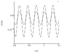
3 | 1 | 1.8 | 4.053 | 90 | 0 | var. | 13.1 | 6a | 6.5 | 14.5 | 6b |
2 | 2.0 | 5.066 | 0 | 0 | 6.8 | 17.9 | 10.2 | 14.5 | |||
4 | 1 | 1.8 | 4.053 | 30 | 0 | var. | 14.9 | 7a | var. | 14.3 | 7b |
2 | 2.0 | 5.066 | 30 | 0 | var. | 18.2 | var. | 14.3 | |||
5 | 1 | 1.8 | 4.053 | 60 | 0 | var. | 13.9 | 8a | var. | 15.8 | 9 |
2 | 2.0 | 5.066 | 10 | 0 | var. | 18.7 | var. | 15.9 | |||
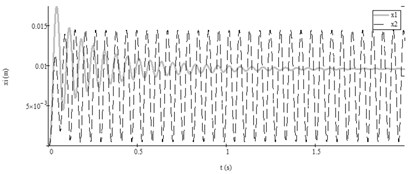
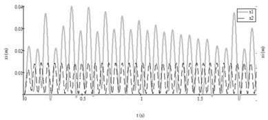
First test. The analysis of the results according to the data of the system from Table 2, Test No. 1 showed that when the vibroexciters worked independently, steady self-exciting vibrations were generated in one of the vibroexciters and the fading vibrations were observed in the other vibroexciter (Fig. 2(a)). The pulsatile pressure fed to the chambers according to the law Eq. (5) with parameters of feeding pressure from Table 2, Test No. 1. In such way feeding pressures were constant: 1.8×10⁵ Pa and 2.0 ×10⁵ Pa. After introducing the aerodynamic link of synchronization, the first vibroexciter also vibrated according to harmonic law, and both vibroexciters operated at only one frequency, i.e., 17.4 Hz (Fig. 3).
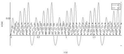
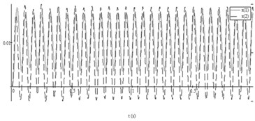
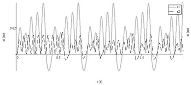
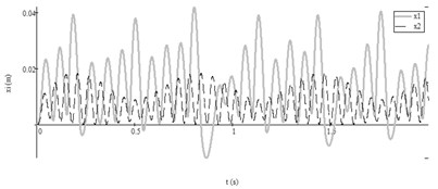
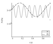
Second test. The feeding pressure started to pulsate (Fig. 4(b)). Numerical research with parameters from Table 2, Test No. 2 showed that the masses of vibroexciters vibrated by different frequencies and the mass according to the periodical anharmonic law (see Fig. 4(a)), when the vibroexciters worked independently. The introduction of synchronization link has caused that the working bodies of vibroexciters vibrate according to the anharmonic law with pulsating amplitudes and similar frequency 16 Hz (Fig. 5).
Fig. 2Results of research with data No. 1 from Table 2: a) autovibrations of both working bodies of vibroexciters without aerodynamic link of synchronization (i= 1, x1 – grey line, i= 2 (x2) – black dashed line), b) functions of feeding pressed air pressures (i= 1, P1t – grey line, i= 2, P2t – black dashed line)
a)
b)
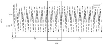
Fig. 3Autovibrations of both working bodies of vibroexciters with aerodynamic link of synchronization (initial data from Table 2, No. 1: i= 1, x1 – grey line, i= 2, x2 – black dashed line): a) vibrations in interval of 2 s, b) enlarged fragment of the a) part
a)
b)
Fig. 4Results of research with data No. 2 from Table 2: a) autovibrations of both working bodies of vibroexciters without aerodynamic link of synchronization (i= 1, x1 – grey line, i= 2 (x2) – black dashed line); b) functions of feeding pressed air pressures (i= 1, P1t – grey line, i= 2, P2t – black dashed line)
a)
b)
Third test. The pressures changed according to the law Eq. (5) with parameters of feeding pressure from Table 2, Test No. 3 and difference of angular frequencies of pulsatile pressure increased. Autovibrations of both working bodies of vibroexciters in interval of 2 s without aerodynamic link is presented in Fig. 6(a). After introducing the aerodynamic link of synchronization, the masses in both vibroexciters started to vibrate according to harmonic law with equal frequency: 14.5 Hz and different amplitudes: 6.5×10⁻³ m and 10.2×10⁻³ m (Fig. 6(b)).
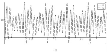
Fourth test. In this test (Table 2, Test No. 4) feeding pressures and pulsated (Fig. 4(b)). Periodical anharmonic vibrations with pulsating amplitudes in the both chambers were obtained when vibroexciters work without aerodynamic link (Fig. 7(a)). The synchronization channel forced both working bodies of vibroexciters to operate at the equal frequency 14.3 Hz and the same phase (see Fig. 7(b)).
Fig. 5Autovibrations of both working bodies of vibroexciters with aerodynamic link of synchronization in interval of 2 s (initial data No. 2 from Table 2: i= 1, x1 – grey line, i= 2, x2 – black dashed line)
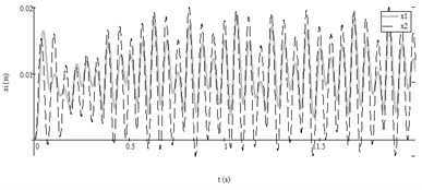
Fig. 6Autovibrations of both working bodies of vibroexciters in interval of 2 s (initial data No. 3 from Table 2: i= 1, x1 – grey line, i= 2, x2 – black dashed line): a) vibrations without aerodynamic link of synchronization, b) vibrations with aerodynamic link
a)
b)
Fig. 7Autovibrations of both working bodies of vibroexciters in interval of 2 s (initial data No. 4 from Table 2: i= 1, x1 – grey line, i= 2, x2 – black dashed line): a) vibrations without aerodynamic link of synchronization, b) vibrations with aerodynamic link
a)
b)
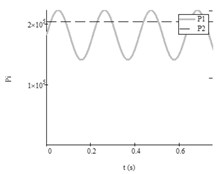
Fifth test. Pulsation functions of feeding air pressure and according to the data from Table 2, Test No. 5 is shown in Fig. 8(b). Autovibrations of both working bodies of vibroexciters without synchronization link is presented in Fig. 8(a). Synchronous operating of both masses was not obtained after introducing the aerodynamic link.
Fig. 8Results of research with data No. 5 from Table2: a) autovibrations of both working bodies of vibroexciters without aerodynamic link of synchronization (i= 1, x1 – grey line, i= 2 (x2) – black dashed line); b) functions of feeding pressed air pressures (i= 1, P1t – grey line, i= 2, P2t – black dashed line)
a)
b)
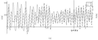
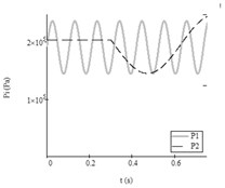
Then pressure parameters have been changed: feeding a constant pressure to one of chamber and after time ( 0.3 s) forcing it to pulsate (Fig. 9(b)). According to numerical research, it forced both working bodies of vibroexciters to operate at the similar frequency and the same phase after time ( 1.6 s). The frequency of mass changed from 8.9 Hz before time to 15.8 Hz after time .
Fig. 9Results of research with data No. 5 from Table2: a) autovibrations of both working bodies of vibroexciters with aerodynamic link of synchronization (i= 1, x1 – grey line, i= 2 (x2) – black dashed line), b) functions of feeding pressed air pressures (i= 1, P1t – grey line, i= 2, P2t – black dashed line)
a)
b)
4. Conclusions
Feeding of pulsatile pressure to one of the chambers can force actuators of vibroexciters to vibrate under anharmonic law with the pulsating amplitude.
When both chambers are fed by pressure of equal pulsation frequency and phase (, ), vibrations of equal frequency and single phase are established after synchronization channel is activated, despite amplitudes are pulsating.
When frequencies of fed pulsatile pressures differ (, 0), periodic anharmonic vibrations of actuators with pulsating amplitudes can be obtained after synchronization channel is activated.
When one of the chambers is initially fed by constant pressure which becomes pulsatile after certain time, vibrations of equal frequency can be achieved in both chambers. In this case, the system’s transition to a synchronous operating mode can be complicated.
References
-
Gecevičius J., et al. Vibrations of complex mechanical systems. Mintis, Vilnius, USSR, Vol. 147, Issue 168, 1969, p. 174-194.
-
Zhang Xueliang, Wen Bangchun, Zhao Chunyu Vibratory synchronization transmission of two exciters in a super-resonant vibrating system. Journal of Mechanical Science and Technology, Vol. 28, Issue 6, 2014, p. 2049-2058.
-
Zhao Chun Yu, Zhang Yi Min, Wen Bang Chun Synchronisation and general dynamic symmetry of a vibrating system with two exciters rotating in opposite directions. Chinese Physics B, 2010, https://doi.org/10.1088/1674-1056/19/3/030301.
-
Kibirkštis E., Pauliukaitis D., Miliūnas V., Ragulskis K. Synchronization of pneumatic vibroexciters on air-cushion operating under self-exciting autovibration regime. Journal of Mechanical Science and Technology, Vol. 31, Issue 9, 2017, p. 4137-4144.
-
Vidyayev D. G. Fluid and Gas Dynamics Separation Processes: a Tutorial. Tomsk Polytechnic University, Tomsk, Russia, 2009, p. 84-86.
About this article

