Abstract
In order to accurately reflect the performance degradation law of the aero-engine rotor system during its life span, a novel multi-state reliability analysis method for rotor system is proposed. The method is based on the combination of the Semi-Markov model with UGF technique. The Semi-Markov model is used to describe the performance degradation process of the components of the rotor system. The UGF technique is utilized to exhibit the relationship between the state performance and the performance probability of the components. Furthermore, the UGF of the entire rotor system is obtained by simplifying the system structure with the modularized method. Therefore, the reliability of the rotor system at different task performance levels can be evaluated easily. A practical case study based on a turboprop engine rotor system is performed to illustrate the implementation and efficiency of the proposed reliability analysis method. Meanwhile, compared with the conventional method, the analysis results indicate that the proposed method can reflect the performance degradation process of the rotor system more veritably and effectively.
1. Introduction
The conventional reliability analysis method simplifies the states of the system to “two states” (“normal working” and “total failure”). However, the large complex equipment and systems usually have more working states except the above two. Such systems are called multi-state system (MSS) [1, 2]. The aero-engine is a MSS which is complex and highly integrated. As an important part of the aero-engine, the rotor system can determine the operation reliability and security of the aero-engine to a great extent. Due to the deterioration of gas performance, fatigue, wear, corrosion and many other reasons in the life cycle of the rotor system, the components will suffer performance degradation or failure. Meanwhile, the rotor system will exhibit multiple performance levels [3, 4].
In recent years, the scholars have made some achievements in the field of the MSS reliability theory. For the study of multi-state reliability analysis methods, the stochastic process and the universal generating function (UGF) are good methods for the reliability analysis of the MSS. The UGF technique has the advantages of simple and immediate in calculation, which can reflect the relationship between the state performance and performance probability of the components and the relationship between the state performance and performance probability of the system. Furthermore, the UGF of the system will be obtained by the UGFs of the components through the corresponding operator rules. Hadi [5] improved the assessment capability of the conventional Risk Priority Number (RPN) in ranking by used the UGF technique. The random process method can describe the states transition process of the components completely. Meanwhile, the performance probability of the components can be obtained by calculating [6]. Wen [7] modeled the energy storage device discharge process based on the Markov model and obtained the evaluation method for the reliability of the solar power generation system. Lu [8] proposed continuous hidden Markov models to assess the condition monitoring status of the online milling tool based on the normal dataset in the same case. Qin [9] discussed the MSS consisted of multi-state components with minor failure and minor repair based on the Markov model and UGF technique. He [10] proposed a novel reliability analysis method for MSS on the basis of triangular fuzzy variety subset Bayesian network (BN). Bentdhoda et al. [11] developed a series of discrete and continuous UGF models in series and parallel structure. Li et al. [12] proposed the definition of the UGF of the system with a variety of performance parameters and the corresponding operator rules. Xu et al. [13] put forward the procedure for evaluating the reserve probability prediction adequacy of autonomous micro-grids combined the UGF with the Markov. Pourkarim et al. [14] dealt with evaluating non-repairable three-state systems reliability and proposed a reliable state definition method based on Markov model. As can be seen in the literature, many studies have been done to enhance the conventional reliability approach. However, there are still two serious issues existed in the research of the multi-state rotor system. In the first place, the transition time distribution of the multi-state components in any state is perhaps more complex, so it’s inappropriate to describe the state transition process of the components or system by using Markov model. For example, Yin et al. [15] solved the steady probability vectors at inspection points, maintenance cost and availability of the production system used Semi-Markov model and the UGF. Shang et al. [16] solved the problem of reliability analysis of multi-state flow reactor system based on the UGF technique and Semi-Markov model, and proved the superiority of the Semi-Markov model compared with Markov model. In the second place, up to now, the research of MSS reliability was less related to the aero-engine rotor system in aviation.
The research objective of this paper is to obtain more accurately performance degradation law of aero-engine rotor system by developing a multi-state reliability analysis method considering partial failure. To do this, Section 2 introduces the Semi-Markov process to construct degradation model of the rotor system. Section 3 reviews the UGF-based modeling approach and defines UGF arithmetic rules. Section 4 introduces the rotor system multi-state reliability analysis procedures based on the proposed method. Section 5 describes a case study of a turboprop engine rotor system. Section 6 makes a brief explanation of the content and significance of this paper done.
2. The Semi-Markov degradation model of the rotor system
The Markov model usually assumes that the state transition time of the components follows the exponential distribution. Nevertheless, the state transition time of airspace components considering partial failure may be subject to a more complex type of probability distribution, not just exponential distribution. The Semi-Markov model is more suitable to describe the condition that the transition time of the components follows arbitrary distribution, such as Weibull distribution, which is widely used in the aviation field. In addition, it can describe the life span distribution pattern of aero-engine more comprehensively. Therefore, the Semi-Markov degradation model of the rotor system is set up to describe the state transition process of the components in this paper.
In order to describe the performance degradation process of the rotor system, considering that the rotor system having n components, where the component j(j=1,2,⋯,n) may have mi(m1,m2,⋯mi) different states with certain probability of performance denoted by an ordering set gj={gj,m1,gj,m2,⋯,gj,mi} in which represents the performance probability of the component in j state mn, mn={m1,m2,⋯mi}. The performance probability Gj(t)of the component j at any time t(t≥0) is random variable taking values in gj, Gj(t)∈gj. The initial state of the component j is mi(t=0), when the component j has been completed the L(T=TL) transitions, if exist all L and mk, ml∈{m1,m2,⋯mi} fit as follows:
Then the stochastic process {Gj(t),TL} is considered as Markov update process, and Q(j)(t) is considered as the kernel matrix of the Semi-Markov model, Q(j)(t)=[Q(j)mkml]. The Semi-Markov states space diagram and corresponding transitions of the component j is shown in Fig. 1.
Fig. 1The Semi-Markov states space diagram of the component j
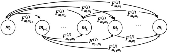
It can be seen from Fig. 1, the component j transfers from initial state mi to state mk with i-1 possible routing paths. If the transition of the component j between different states is viewed as an event and the probability distribution function is known, the implementation of the transition lies in which one transfer event occurs first. If the event k occurs first, the component j will be transferred to state mk, so the time interval from initial state mi(t=0) to state mk is T(j)mimk and the probability distribution function is F(j)mimk. Suppose that the transfer of the component j between different states is independent of each other, so the probability Q(j)mkml can be expressed by Eq. (1) as follows:
Finally, the kernel matrix of the componentjcan be obtained as follows:
Suppose that the ρ(j)miml(t) represents the probability that the component j will be transferred from the initial moment t(t=0) in state mi to the moment t(t≥0) in state mi, again denoted as mi-1. And mk can be solved by the major equation in the Semi-Markov theory, as shown in Eq. (4):
Among them:
In Eq. (4), τ (0≤τ≤t) stands for time variables, q(j)mimn(τ) is the differential of Q(j)mimn(t) which represents the transition rate of the probability function Q(j)mimn(t) at the moment τ. δmiml as the indicating function, F(j)mlm1 is the non-conditional probability distribution function of the component j in state mi at dwell time, which indicates the probability that the component F(j)mi-1m1 will leave the state mi at the moment t. Therefore, after determining the kernel matrix, the probability in each state can be obtained.
3. Obtaining the UGF for the rotor system based on the UGF technique
As soon as the performance probability of the components is given, the performance probability of the rotor system can be determined. Considering that the rotor system has many components and the structure is complex, in order to reduce the calculation complexity, the modularized method is used to simplify the rotor system.
The rotor system is divided into n modules and each state of the components is statistically independent. Then the UGF of the component j within the module f(f=1,2,⋯,n) of the rotor system can be shown as:
In Eq. (5), S is an auxiliary variable, g(f)j,mm and P(f)j,mm are the state performance and the performance probability of the component j at any time t(t≥0) respectively obtained in Section 2. In which, j=1,2,⋯,n and mm=m1,m2,⋯,mi.
The UGF of the module f is:
In Eq. (6), the coefficients of the UGF of the module f are multiplied. The function ψ(⋅) is known as UGF arithmetic rule, which reflects the relationship between the state performance and components of the module f. The following arithmetic rules are defined according to the structure and physical characteristics of the module f.
Rule 1: When the components of the module f are series structure, the performance level of the module f is equal to the performance level of the bottleneck component. Therefore, the arithmetic rule is defined as:
Rule 2: When the components of module f are parallel structure, the arithmetic rules are divided into two cases.
If the performance level of the module f is evenly shared by each component, the arithmetic rule is defined as:
If the performance level of the module f is assumed by a more capable component, the arithmetic rule is defined as:
According to the analysis of the above algorithm, the UGF of the rotor system can be obtained as:
Again, denoted as:
In Eq. (11), {M1,M2,⋯,Mi} expresses the state performance set of the rotor system, PS,Mn(t) indicates the probability of the rotor system in state Mm, Mm=M1,M2,⋯,Mi.
4. The rotor system multi-state reliability analysis based on the proposed method
According to the above introduction, the implementation of the multi-state reliability analysis method for the rotor system based on the combination of the Semi-Markov model and UGF technique can be divided into four-stage:
Stage 1: Analyzing the performance and structure of the rotor system according its structure and working principle. First, the reliability block diagram (RBD) of the rotor system can be obtained by analyzing its structure. Then, the performance structure diagram of the rotor system can be obtained by analyzing its performance level and performance parameter.
Stage 2: Determining the life span distribution parameter of the components in the rotor system. Building differential equations for each component of the rotor system respectively based on Semi-Markov method. Therefore, by solving these equations, the performance probability for every component at each time instanttcan be obtained by the major equation.
Stage 3: After determining state probabilities for all elements, the individual UGF for each component would be defined. Using the modularized method to simplify the rotor system tonmodules according to its structure. Then by using arithmetic rules over UGF of individual components and their combinations, one can obtain the resulting UGF for each module and the entire rotor system using simple algebraic operations.
Stage 4: After obtaining the resulting UGF of the entire rotor system, one can determine the reliability index of the rotor system, as shown in the following description.
Defining that the reliability of a MSS as the probability the system staying in the subset of acceptable states. Thus, based on the task performance level w, the reliability of the rotor system Rs(w) is usually defined as the reliability the rotor system performance probability is greater than w [16]. According to the Eq. (11), the reliability index of the rotor system can be obtained [17] and the reliability of the rotor system can be determined as follows:
In Eq. (12), P(gS,Mm-w≥0) is indicator function, which means the result is 1 in condition of gS,Mn-w≥0, otherwise the result is 0. Pr denotes the probability function.
5. Application
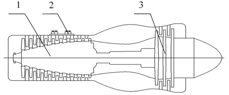
A case study is employed to verify the applicability of the proposed method. The case is a turboprop engine rotor system. Also, the method is compared with the conventional reliability analysis method. The structure diagram of the turboprop engine is shown in Fig. 2.
Fig. 2The structure diagram of the turboprop engine. 1-10 – stage axial compressor; 2 – relief valve, 3-3 – stage axial flow reaction turbine
5.1. Performance and structure analysis
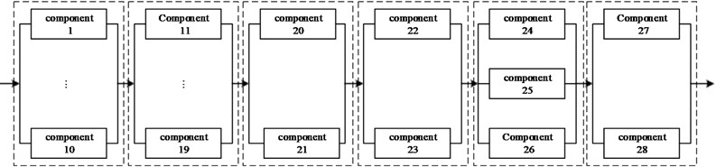
As shown in Fig. 2, the rotor system of the turboprop engine is mainly composed of 10 stage axial compressor and 3 stage axial flow reaction turbine. And four relief valves are installed outside the compressor gate, there are two relief valves at fifth stage and two at eighth stage. According to the working principle and structure of the rotor system, the RBD of the rotor system can be expressed in Fig. 3. It is mainly divided into 6 modules, the modules are series connection and the components in each module are parallel connection. In Fig. 3, the components 1-10 in module 1 represent the first to ten stage rotor of the compressor subsystem, and the components 24-26 in module 5 represent the first to three stage rotor of the turbine subsystem, wherein the major components include vanes, plates, spindles, and bearings to achieve intake and boost supercharging. The components 11-19 in module 2 represent the first to nine stage stator of the compressor subsystem, and the components 27-28 in module 6 represent the first to two stage stator of the turbine subsystem, wherein the main components include power-brakes and rectifiers to achieve air rectification.
Fig. 3The RBD of the rotor system
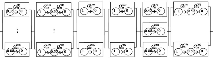
Defining the performance level of the components is expressed as the contribution rate of the components in different states to the performance of the whole rotor system in normal working state [18]. The efficiency of intake air compressor is used as a performance parameter to describe the work capacity of the rotor of the compressor subsystem and the stator of the turbine subsystem. Among them, the rotor is configured as a component with normal working and total failure performance states. The performance indexes of the first stage rotor of compressor are 0.35 and 0 respectively. The performance indexes of the second stage rotor of compressor are 0.4 and 0 respectively. Analogously, the performance indexes of the ten stage rotor of compressor are 0.8 and 0. The performance indexes of three stage rotors of turbine are 0.4 and 0; 0 and 0.6; 0 and 0.8. The stator is configured as a degenerated component with normal working, partial failure and total failure states. The performance indexes are 1, 0.5 and 0 respectively. The components 20-23 in module 3-4 represent the four relief valves to achieve rapid exhaust and prevent compressor from surging. Considering that relief valve have opening and closing states, so the performance indexes are 1 and 0 respectively.
The performance structure diagram of the rotor system is established in Fig. 4.
Fig. 4The performance structure diagram of the rotor system
In order to study scientifically, the following assumptions are made as follows:
1. The rotor system is non-repairable, and all components of the rotor system are in good condition at the initial moment (t=0). In addition, it will be abandoned when the component failed.
2. In the process of reliability analysis, two kinds of failure including wear and corrode are considered.
3. A large portion of conventional life span distribution of the component usually assumes that the life span distribution of the rotor system satisfies the two parameter Weibull distribution regardless of the kind of the component. This is not practical in reality and may result in an inaccurate parametric estimation. Therefore, it is assumed that the rotor system component life obeys Weibull three parameters. The random variables related to this distribution are independent of each other. The time interval is T(j)mkml-W(m,η,γ;t), and the probability distribution function is:
where, α is shape parameter, β is scale parameter, γ is location parameter and t is time variable.
4. In the process of calculating UGF, the performance level of each module is assumed by the component with stronger ability. The transition probability of each component is the same.
Table 1The Weibull distribution parameter of the components
Module | Component | Distribution parameter | |||||
α32 | β32 | γ32 | α21 | β21 | γ21 | ||
Module 1 | 1-10 | 1.16 | 2223.73 | 1566.4 | |||
Module 2 | 11-19 | 1.52 | 2516 | 1856 | 1.23 | 2455.64 | 1690.8 |
Module 3 | 20-21 | 1.76 | 1538.3 | 779.6 | |||
Module 4 | 22-23 | 1.76 | 1538.3 | 779.6 | |||
Module 5 | 24-26 | 1.20 | 2516.7 | 1392.9 | |||
Module 6 | 27-28 | 1.76 | 2086 | 2487 | 2.642 | 4488.6 | –324.7 |
According to the above assumptions and the engineering experience values of the Weibull distribution parameter, the distribution parameters of each component are determined by maximum likelihood estimation as shown in Table 1.
5.2. Calculating the performance probability and UGF of the components
According to the calculation method of performance probability described in Section 2, take the component 11 (the first component of the module 2) as an example to illustrate.
The probability distribution functions of the component 11 are as follows:
The elements in the kernel matrix are as follows:
Then, the result of the kernel matrix is as follows:
For the component 11 with three states, we can get Eq. (19) by Eq. (4):
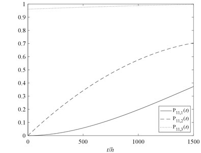
According to the principle of calculus, we use Matlab software programming to solve the Eq. (19). Then, the probability of the component 11 in normal working performance state, partial failure performance state and total failure performance state can be obtained. The performance probability of the component 11 in each state can be obtained as shown in Fig. 5.
Fig. 5The performance probability of the component 11
Meanwhile, we can obtain the UGF of the component 11, as shown in Eq. (20):
According to assumption 4, we can know as:
For the components with two states, such as the component 1 from module 1, according to the Eq. (4), we can get the following equation as shown in Eq. (21):
By using Matlab software programming to solve the Eq. (22), we can obtain the performance probability of the component 1 in each state. The state probability of other components can be obtained by changing the life parameters in Eq. (20) and Eq. (22).
5.3. Modularized processing
According to arithmetic rules of function ψ(⋅) defined in Section 3, the RBD of the rotor system shown in the Fig. 3 can be simplified by modularized processing. The modularized diagram of the rotor system is shown in Fig. 6.
Fig. 6The modularized diagram of the rotor system

Afterwards, the state performance and performance probability of each module can be obtained. The UGF of the module 1 can be obtained by Eq. (6) as follows:
+P1,1(t)2P1,2(t)⋅S0.7+P1,1(t)3P1,2(t)⋅S0.65
+P1,1(t)4P1,2(t)⋅S0.6+P1,1(t)5P1,2(t)⋅S0.55
+P1,1(t)6P1,2(t)⋅S0.5+P1,1(t)7P1,2(t)⋅S0.45
+P1,1(t)8P1,2(t)⋅S0.4+P1,1(t)9P1,2(t)⋅S0.35+P1,1(t)10⋅S0.
Where, the performance probability of the module 1 is shown in Fig. 7 as functions of time.
Similarly, the performance probability of other modules can also be obtained by Eq. (6).
5.4. Calculating the performance probability and UGF of the rotor system
According to the UGF of the module 1-6, the UGF of the rotor system in the following form:
+PS,0.6(t)⋅S0.6+PS,0.55(t)⋅S0.55+PS,0.5(t)⋅S0.5+PS,0.45(t)⋅S0.45
+PS,0.4(t)⋅S0.4+PS,0.35(t)⋅S0.35+PS,0(t)⋅S0
where, the probability of the rotor system in each performance state is presented in Fig. 8 as functions of time.
5.5. The reliability analysis with two kinds of methods
5.5.1. The multi-state reliability analysis
Based on the UGF U(S), one can obtain the reliability index by Eq. (12). In this article, it is assumed that the requirement of reliability analysis is to evaluate the reliability of the rotor system running 1000 hours.
Therefore, the reliability of the rotor system in normal working state, partial failure state and total failure state can be obtained in following formula:
It is assumed that the task performance level w of the multi-state rotor system is selected as 0.35, so the reliability of the rotor system can be obtained in following formula:
+PS,0.55(t)+PS,0.6(t)+PS,0.65(t)+PS,0.7(t)+PS,0.75(t)+PS,0.8(t).
However, in actual situation, the performance of aero-engine varies with the operating environment. Meanwhile, the task performance level w of the rotor system is also different. Therefore, the task performance level w is respectively selected as 0.35, 0.55 and 0.75 to analyze reliability of the multi-state rotor system, the results are shown in Fig. 9.
Fig. 7The performance probability of the module 1
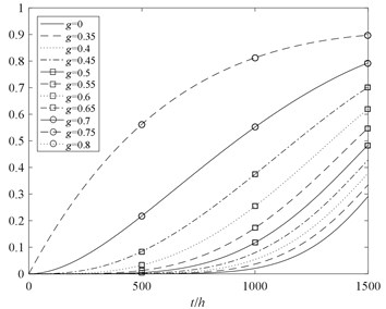
Fig. 8The performance probability of the rotor system
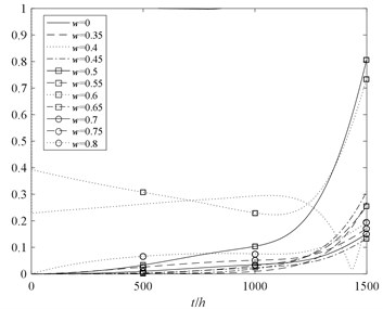
Fig. 9The reliability analysis of the rotor system with two kinds of methods
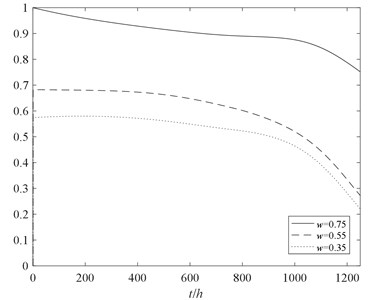
Fig. 10The reliability analysis of multi-state rotor system at different performance levels
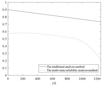
5.5.2. The conventional reliability analysis
For the conventional reliability analysis method, “normal working” and “total failure” are simply considered. When the rotor system is in normal working state, it means that all components must be functional and any kinds of failure should not occur. To avoid the difficulty of equivalence from the multi-state performance probability to the two states performance probability, conservatively considered that the reliability of never invalidated of the components under the multi-state is equivalent to the reliability in normal working state under conventional method. In the task performance level w of 0.35, the reliability of the rotor system obtained by the two methods are shown in Fig. 10.
5.6. Results analysis
The following conclusions can be drawn from Fig. 9 and Fig. 10:
1. The trend of the reliability of the rotor system considering partial failure is decreasing, and with the increase of time decreased faster. Therefore, the partial failure state is not able to be ignored in comparison with the conventional method.
2. With the increase of task performance level w, the reliability of multi-state rotor system decreases gradually. It’s of great significance to research the reliability of multi-state rotor system at different performance levels.
3. Without considering effects of performance degradation of the partial failure state, the reliability result obtained by conventional method is higher than multi-state reliability analysis method. The multi-state reliability analysis method can better reflect the process of performance degradation of the rotor system.
6. Conclusions
In this paper, a new multi-state reliability analysis method for the rotor system is suggested by combining the classical Semi-Markov model and UGF technique. The presented method is suitable for engineering applications because it can obtain more efficient and accurate reliability analysis than the conventional methods. Until now, the general multi-state reliability analysis method did not extend to a multi-state rotor system.
The advantages of using the proposed method are: 1. Simplification of the rotor system state transition model building. The RBD is used to describe the logical relations between the rotor system and the components. The state combination of the rotor system and the expression of each state probability can be obtained by combinatorial operation of UGF. Instead of building a complex state transition model for the entire rotor system, one should build n single component state transition models. Meanwhile, using the modularization method creatively to make the calculation time and the complexity of the UGF reduced greatly. 2. Simplification of the rotor system state probability calculating. When using this method to calculate the state probability of the rotor system, it is only necessary to solve the integral equation of the state probability of each component separately, instead of solving the integral equation of the state probability of the rotor system as a whole. The computational complexity of the latter is obviously higher than that of the former because of the large number of the rotor system states will cause “dimension damnation”.
Therefore, the research findings can provide a strong theoretical guidance and support for the improve production safety and reliability of the rotor system, which is of great significance to the operation management and reliability analysis of large complex systems and equipment. However, the components are not repaired in this article, further research can be devoted to overcoming this limitation. Reliability optimization and evaluation of the rotor system can be studied based on our study here, and other effective reliability analysis methods can be used in further research.
References
-
Huang J. S., Zuo M. J. Dominant multi-state systems. IEEE Transactions on Reliability, Vol. 53, Issue 3, 2004, p. 362-368.
-
Levitin G. The Universal Generating Function in Reliability Analysis and Optimization. Springer, London, 2005.
-
Rafiee K., Feng Q., Coit, D. W. Condition-based maintenance for repairable deteriorating systems subject to a generalized mixed shock model. IEEE Transactions on Reliability, Vol. 64, Issue 4, 2015, p. 1164-1174.
-
Deng S. E., Fu J. H., Wang Y. S., Yang H. S. Analysis on dynamic characteristics of aero-engine rolling bearing/dual-rotor system. Journal of Aerospace Power, Vol. 28, Issue 1, 2013, p. 195-204.
-
Hadi A. K., Indra G., Yi M. Applying UGF concept to enhance the assessment capability of FMEA. Quality and Reliability Engineering International, Vol. 32, Issue 3, 2016, p. 1085-1093.
-
Taboada H. A., Espiritu J. F., Coit D. W. MOMS-GA: A multi-objective multi-state genetic algorithm for system reliability optimization design problem. IEEE Transactions on Reliability, Vol. 57, Issue 1, 2008, p. 182-191.
-
Wu L., Wen C., Ren H. Reliability evaluation of the solar power system based on the Markov chain method. Quality and Reliability Engineering International, Vol. 41, Issue 15, 2017, p. 2509-2516.
-
Lu C., Li T., Liu H. Online milling tool condition monitoring with a single continuous hidden Markov models approach. Journal of Vibroengineering, Vol. 16, Issue 5, 2014, p. 2448-2457.
-
Qin J., Niu Y., Li Z. A combined method for reliability analysis of multi-state system of minor-repairable components. Eksploatacja i Nieza wodnosc-Maintenance and Reliability, Vol. 18, Issue 1, 2016, p. 80-88.
-
He Q., Zha Y., Zhang R., Sun Q., Liu T. Reliability analysis for multi-state system based on triangular fuzzy variety subset Bayesian networks. Eksploatacja i Niezawodnosc-Maintenance and Reliability, Vol. 19, Issue 2, 2017, p. 152-165.
-
Bentolhoda J., Lance F. A universal generating function-based multi-state system performance model subject to correlated failures. Reliability Engineering and System Safety, Vol. 152, 2016, p. 16-27.
-
Li C. Y., Chen X., Yi X. S., Tao J. Y. Reliability analysis of multi mate system with multiple performance parameters based on vector-universal generating function. Acta Armamentarii, Vol. 31, Issue 12, 2010, p. 1604-1610.
-
Xu S., Wang Y., Tang W., Yan T., Ma J., Zhang X. L. Adequacy evaluation of spinning reserve for autonomous microgrids based on universal generating function method. Automation of Electric Power Systems, Vol. 40, Issue 21, 2016, p. 137-145.
-
Pourkarim G. P., Sharifi M., Niaki S., Zaretalab A. Reliability evaluation of non-reparable three-state systems using Markov model and its comparison with the UGF and the recursive methods. Reliability Engineering and System Safety, Vol. 129, 2014, p. 29-35.
-
Yin M. A., Sun Z. L., Wang J., Zhang Y. Structure and maintenance policy of a multi-state series-parallel system. Acta Armamentarii, Vol. 37, Issue 11, 2016, p. 3395-3403.
-
Shang Y. L., Cai Q., Zhao X. W., Zhao Y. G. Availability analysis of nuclear power system with performance degradation and multi-level support capacity. Nuclear Power Engineering, Vol. 48, Issue 4, 2014, p. 703-708.
-
Lisnianski A., Levitin G. Multi-State System Reliability: Assessment, Optimization and Application. World Scientific, New Jersey/London/Singapore, 2003.
-
Pang G., Shang C. X., Cai J. Y., Liang Y. Y., Meng Y. F. Research on imperfect maintenance decision for multi-state system based on Semi-Markov model. Acta Aeronautica et Astronautica Sinica, Vol. 37, Issue 2, 2016, p. 1-5.
Cited by
About this article

This research is financially supported by the National Science Foundation of China (Grant No. 51275374) and the Fund Project of Science Technology on Reliability and Environmental Engineering Key Laboratory.
