Abstract
This paper presents a two-step approach for structural damage identification in beam structure using the influence line and bird mating optimizer (BMO). Local damage is simulated as the reduction of the elemental Young’s modulus and mass of beam element. The technique for damage localization based on influence line and its derivatives before and after damage for beam structure was outlined. An objective function comprised of dynamic acceleration is utilized for BMO algorithm. The dynamic response data under external force is calculated by Newmark integration method. Numerical examples of a simply supported beam was investigated. Effect of measurement noise is studied. Studies in the paper indicate that the proposed method is efficient and robust for identifying damages in beam structures.
1. Introduction
It is well-known that structures are suffering from all kinds of damage problems, thus a reliable structural damage identification method is needed.
Vibration based damage identification basically comprised of methods using data from frequency domain and time domain. In the last few decades, many damage identification methods have been developed using the vibration data in frequency domain [1-4]. Moreover, with the advantage of massive vibration data, methods in time domain [5-8] emerged serve as a more reliable but complicated aspect in damage identification.
In mathematical aspect, damage identification problem can be regarded as an optimization problem that aims to find the optimal solution of an objective. And with the fast development of computation, more attention was paid in algorithm these years. Neural network was among the first to be adopted to identified damage [9, 10], and therefore others heuristic algorithm such as genetic algorithm (GA) [11], particle swarm optimization (PSO) [12] and artificial bee colony (ABC) [13] are proved to the available in damage identification.
A new heuristic algorithm named Bird Mating Optimizer (BMO) was proposed by Askarzadeh [14, 15] recently, which imitates the mating behavior of birds. The algorithm was simulated and compared with GA, PSO and GSO [14] and had better accuracy.
In this paper, a two-step method for damage identification is proposed, damage is quantified as both stiffness and mass reduction in different levels. The disadvantage of heuristic algorithm is the probability of local optimum, especially with large amount of identified parameters existed. Here the displacement influence line will be utilized to determine the damage location so as to reduce the number of parameters. Then, the damage is quantified in the second step using bird mating optimizer. An objective function is established by minimizing the discrepancies between the simulated ‘measured’ dynamic acceleration responses and calculated ones. A simulation of simply supported beam is studied to show the promising results of the method.
2. Damage identification methodology
2.1. Damage model construction
The finite element method is utilized to calculate the responses of the damage beams. Without loss of generality, we quantify the local damage as the reduction of both stiffness and mass parameters in damage element(s). For a structure with elements, we preset -dimension vectors and , whose elements and 1, 2,…, are between 0 and 1, stand for the damage parameters of stiffness and mass of the th element, respectively:
where and represent the elemental stiffness and mass matrices for element , and , as global stiffness and mass matrices. The dynamic responses of the damaged structure can be obtained by Eq. (2) using direct integration method:
where is the damping matrix of the system and Rayleigh damping is adopted that , and are two constants determined by two given damping ratios that corresponding to the first two modal frequencies of the structure.
2.2. Localization of the damage by influence line residue
The localization of damage is totally based on the static displacement of the beam when a external force exerted on it. In a beam structure with length , if loaded with force , the static deflection of point can be obtained by Eq. (3):
where is the bending moment of beam when only external force exerted on the beam, and is the bending moment when a unit force exerts at the measuring point , respectively, is the deflection function of the beam.
If we assume that there is damage existing between and with stiffness damage index , then the residue between damaged and intact situation is:
If we set the external force as a single moving load whose location is , then the displacement influence line residue for point is formed:
The value of within will change with moving from to . In mechanics aspect, the change is produce directly to the change of shear force. Taking the partial derivative of with respective to of Eq. (5) we get Eq. (6):
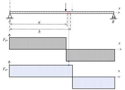
where represents the shear force of the beam caused by moving load. A sudden change of will occur within , which can be explained as: when a moving force passes through a damaged area, the shear force within the area would change from positive to negative as is illustrated in Fig. 1.
Fig. 1The change of shear force Δfxp(xs,xp)
For a structure with multiple damages, the values of will be the linear sum of derivative of influence line residue (DILR) of every damage individual. For discretized model with elements and elemental length is , the discrete influence line residue is:
where is the number of damages. One can further specify the change of DILR by taking the derivative of DILR(DDILR) to again. In the discretized model, the second-order central difference quotient is used to calculate the DDILR as shown in Eq. (8), where the damage parts will present as non-zero DDILR values:
Note that in numerical study, a damage is assumed as an elemental damage that associates with two nodes, on the other hand is nodal value, so a single damage will be presented as two consecutive changes of corresponding nodes on the curve.
2.3. Objective function for identification assessment
To get results of higher precision especially of structure with lots of elements, the acceleration responses was to made up the objective function. For node the acceleration responses vector with sampled time points can be expressed as:
By measuring the deviance of acceleration responses between actual and calculated in the form of Modal Assurance Criterion (MAC):
where the superscript and denote that the responses originated from calculation and measurement respectively. When the calculation in accordance with the measured data, the reaches 1, so the objective function can be:
where is the weighting factor of the acceleration data and is the number of the measuring points.
3. Numerical simulation
The identification procedure is shown in. A simply supported beam made of aluminum is the numerical example of the study, with length 10 m and cross-sectional width 0.6 m and height 0.4 m, the beam is discretized into 12 Euler-Bernoulli elements, Young’s modulus is 6.9 GPa and mass density 2700 kg/m3. There are three designed damages, elements 3, 8 and 9 with Young’s modulus reduction by 10 %, 20 % and 15 %, mass reduction by 5 %, 10 % and 5 % respectively. The damping model is Rayleigh damping and the two Rayleigh coefficients are both assumed to be 0.01.
To maintain practicality, 3 % random noise presented by Eq. (15) is added to the displacement values during localization:
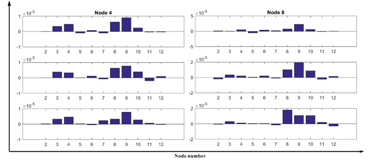
where is the noise level, two sensors are set in nodes 4 and 8, and the localization is processed three times to reduce the affection of noise. The DDILR are shown in Fig. 2, nodes 3, 4, 8, 9, 10 show stable changes in the chart of sensor set in node 4, and nodes 8, 9 and 10 have constant trend in the chart of the other sensor in node 8. Thus, the corresponding elements 3, 8 and 9 are selected as suspected elements.
Fig. 2DDILR of the simply supported beam
For acceleration responses , a Gaussian distributed random noise with zero mean and unit standard deviation is added as Eq. (16), where stands for the standard deviation of the acceleration responses in time history. The weighting factors of the accMAC are all set as one:
The acceleration responses of the structure of a constant sinusoidal force acting at node 7 in the global direction with is calculated by Newmark-beta method, the time increment is 0.01 second and the time duration for the response calculation is 6.0 seconds and 600 time steps in total. The arrangement of acceleration measurements are two nodes locating at nodes 5, 8.
The identified results of noise level 5 % and 10 % are shown in Fig. 3, with comparison to the result of noise free in condition. In noise free condition the identification yielded good results with maximum relative error 0.9667 % by elemental stiffness of the 3rd element, in low noise level the result is still satisfactory with maximum deviation less than 5 %, and in high noise level the maximum relative error is 5.2526 % which is not too great compared to the result of 5 %.
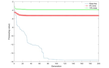
In the best logarithmic fitness values chart show in Fig. 4, it can be observed that with higher noise level, the searching process reach convergence faster but on the other hand the precision dropped.
Fig. 3Comparison of identification results under different noise levels
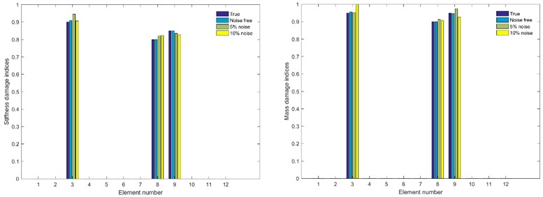
Fig. 4Comparison of logarithmic best fitness under different noise levels
4. Conclusions
By making use of the influence line residue and acceleration data, a two-step damage detection method for beam structures is proposed in this study. A damage model combined with stiffness and mass reduction is applied. The influence line data of displacement is used to reduce the dimension of the identified parameters, objective function based on acceleration and the form of MAC (Modal Assurance Criterion) is established, then BMO is used to minimizing the discrepancies between the simulated measured data and the data from damaged structure. A simply supported beam numerical simulation reflect the effectiveness of the proposed method, results under three different noise levels demonstrated that the proposed method is insensitive to measurement noise, which also manifested the robustness of the method.
References
-
Cawley P., Adams R. D. The location of defects in structures from measurements of natural frequencies. The Journal of Strain Analysis for Engineering Design, Vol. 14, Issue 2, 1979, p. 49-57.
-
Pandey A. K., Biswas M., Samman M. M. Damage detection from changes in curvature mode shapes. Journal of Sound Vibration, Vol. 145, Issue 2, 1991, p. 321-332.
-
Lee J. Identification of multiple cracks in a beam using natural frequencies. Journal of Sound and Vibration, Vol. 320, Issue 3, 2009, p. 482-490.
-
Zhong S., Oyadiji S. O. Detection of cracks in simply-supported beams by continuous wavelet transform of reconstructed modal data. Computers and Structures, Vol. 89, Issues 1-2, 2011, p. 127-148.
-
Majumder L., Manohar C. S. A time-domain approach for damage detection in beam structures using vibration data with a moving oscillator as an excitation source. Journal of Sound and Vibration, Vol. 268, Issue 4, 2003, p. 699-716.
-
Zhu X. Q., Law S. S. Wavelet-based crack identification of bridge beam from operational deflection time history. International Journal of Solids and Structures, Vol. 43, Issues 7-8, 2006, p. 2299-2317.
-
Law S. S., Lu Z. R. Crack identification in beam from dynamic responses. Journal of Sound and Vibration, Vol. 285, Issues 4-5, 2005, p. 967-987.
-
Lu X. B., Liu J. K., Lu Z. R. A two-step approach for crack identification in beam. Journal of Sound and Vibration, Vol. 332, Issue 2, 2013, p. 282-293.
-
Wu X., Ghaboussi J., Jr J. H. G. Use of neural networks in detection of structural damage. British Journal of Surgery, Vol. 81, Issue 11, 1992, p. 578-581.
-
Rhim J., Lee S. W. A neural network approach for damage detection and identification of structures. Computational Mechanics, Vol. 16, Issue 6, 1995, p. 437-443.
-
Maity D., Tripathy R. R. Damage assessment of structures from changes in natural frequencies using genetic algorithm. Structural Engineering and Mechanics, Vol. 19, Issue 1, 2005, p. 21-42.
-
Seyedpoor S. M. A two stage method for structural damage detection using a modal strain energy based index and particle swarm optimization. International Journal of Non-Linear Mechanics, Vol. 47, Issue 1, 2012, p. 1-8.
-
Xu H. J., Ding Z. H., Lu Z. R., Liu J. K. Structural damage detection based on chaotic artificial bee colony algorithm. Structural Engineering and Mechanics, Vol. 55, Issue 6, 2015, p. 1223-1239.
-
Askarzadeh A. Bird mating optimizer: an optimization algorithm inspired by bird mating strategies. Communications in Nonlinear Science and Numerical Simulation, Vol. 19, Issue 4, 2014, p. 1213-1228.
-
Askarzadeh A. Parameter estimation of fuel cell polarization curve using BMO algorithm. International Journal of Hydrogen Energy, Vol. 38, Issue 35, 2013, p. 15405-15413.
About this article

This work is supported by the National Natural Science Foundation of China (11572356), the Guangdong Province Science and Technology Program (2016A020223006), and Guangdong Province Natural Science Foundation (2015A030313126). Such financial aids are gratefully acknowledged.
