Abstract
Paper contains a report of the part of works conducted in the research and development project concerned with a modernization of freight wagons during their periodic repair. The aim of this research was to obtain better exploitation conditions of freight cars. Two elements of those works are presented: a computer aided analysis of the freight car’s CAD model and results and analysis of the real object elements’ vibrations during exploitation. The aim of numerical analysis was to determine the maximal permitted speed at which the car does not go off the rails. These tests were performed using the “Motion Simulation” module of the software of the CAD/CAE/CAM class Siemens PLM NX. The real freight car’s elements vibration were measured and analysed in order to verify if it is possible to create a mechatronic approach for technical condition analysis of modernized freight cars during their exploitation based on their dynamic response as well as to validate the CAD model of the considered freight car.
1. Introduction
Nowadays, a lot of effort is spent on development of any types of devices that are used by a human kind because new materials and new technologies are opening brand new possibilities for designers and engineers. They have the opportunity to apply new materials and new methodology to design devices and systems that, for example are more effective, have better properties and lower costs of production. The new opportunities are also results of the possibility of smart materials application, so the materials that can change one or more of their properties during operations and this change can be controlled. This development process relates also to such technical devices as freight cars [1-5]. On the other hand, computer aided methods of designing, manufacturing and product life cycle management are also powerful tools that helps to design and produce modern technical devices [6-10]. Modern systems include elements from different science areas, such as mechanics, electronics and informatics. Such connection brings new possibilities and new mechatronic approach.
In spite of all of those benefits of modern engineering it is also important to take into account that designed technical system should also has a positive influence onto realization of the principles of sustainable development by both, the method of its production, as well as the whole product life cycle. The principles of sustainable development are understood as to ensure the development of the present generation, among others in terms of economic growth and meet its needs, while maintaining opportunities for further development and meet the needs of future generations. It is an idea that is committed to social justice through economic and environmental efficiency projects undertaken. In this light, the development of currently used technical devices that aim is to obtain their longer exploitation that will lower demand for raw materials and improve their use is the idea of the research project which results are presented in this paper as well as is the main idea of other researchers work.
This paper contains a report of the part of works conducted in the research and development project entitled “Analytical and experimental tests and determination of characteristics of components working as assemblies of innovative structures of repaired wagons”. This project was realised within the Program of Applied Research by Institute of Engineering Processes Automation and Integrated Manufacturing Systems of Silesian University of Technology, together with consortium partners: company DB Schenker Rail Poland SA and Germaz. The main objective of the project was to develop a technology of modernisation of freight wagons for the transport of coal and aggregates, through the use of innovative materials and technologies to repair this type of wagons during periodic repairs. Actions which have been undertaken within the project are to improve the operating conditions considered types of wagons by increasing their resistance to corrosion and freezes transported cargo to the shell of the body in the winter conditions, and thus an easier unloading [11-13]. An additional objective was also verification of strength of modernised carriages and an estimation of the possibility of reducing their weight, while maintaining or increasing the permissible load [14]. One of elements of the project was also to develop a system for diagnosing the technical condition of the modernised shell of wagon body during operation. For this purpose, the use of non-destructive testing methods of the technical state of constructions were used, including methods based on the analysis of a dynamic response of the object. Therefore, research was conducted which examines the possibility of use of the foils with piezoelectric properties as sensors used in the system of vibration measurement of tested items [15]. These research efforts are a continuation of the previous work related to the analysis of possibilities to use of composite materials as a part of the wagon’s boxes shell.
Application of the composite panels to the freight wagon’s body shell was proposed as the solution that can solve mentioned problems during exploitation of freight wagons. The composite panels composed of fibreglass and epoxy resin were proposed. They will be mounted on the body shell using rivet nuts. What is more the body shell of the modernised freight wagon will be painted using an anti-corrosion agent. The application of new materials in the considered freight wagons is connected with the need to conduct a series of studies of the proposed materials properties, taking into account their strength analysis, abrasion resistance, fatigue resistance, and other properties important because of the working conditions in the modernised freight wagons. Selected results of carried out analysis are presented in this paper.
Presented topics of freight cars modernization technology based on application of new materials as well as mechatroic systems for their technical condition monitoring are very important issues. A lot of researchers and engineers from international engineering community are paying attention to those issues [1-10, 21, 23] and authors of this work believe that presented in this paper results of carried out studies could be interested in other researches and could inspire other ideas.
2. Computer aided testing of prototype structural elements of freight cars
The introduced structural change consists in the use of composite panels which should protect the steel plating of a wagon body. Therefore, it is necessary to carry out a series of studies to check, among others, the strength parameters of the adopted constructional solution. For this purpose, it is necessary to determine the maximal value of the force, derived from transported freight, which acts on the side walls of a wagon. In the work is presented a series of tests related to motion analysis of a freight wagon of the 418V type. The aim of numerical analysis was to determine the maximal permitted speed at which the car does not go off the rails. These tests were performed using the “Motion Simulation” module of the software of the CAD/CAE/CAM class Siemens PLM NX. It has been created a model prepared for motion simulation, in which have been defined joints necessary for the proper mapping of the wagon motion on a track way. In order to elaborate a better mapping of motion of the analysed system the created model, prepared for simulation tests, has been refined. The refinement depended on utilization, in the wagon model, the elastic and elastic-damping components.
A dynamic increase of an area of application of composite materials have caused the development of computer tools, which aid a composite material modelling and their strength analysis with use the finite element method. Also, in the presented research work composite materials were proposed as the solution of the problems occurring during exploitation of freight cars. It was necessary to carry out some tools for computer aided analysis of proposed structures. One of the computer tools that can be used to model and verify the composite materials is PLM Siemenes NX software. Presented methods of computer modelling of composite material let on the composite materials modelling which consist of a matrix and reinforcement and composite materials which are the plies composition of any material.
2.1. Analysis of motion of a freight wagon in an advanced engineering environment
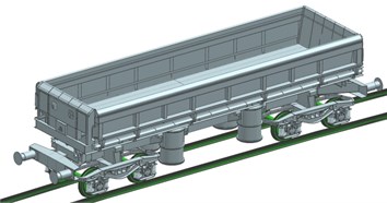
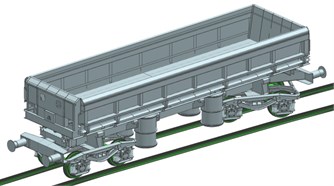
The introduction of various modifications in constructional solutions of the existing technical means, which aim is to improve their chosen properties, requires every time additional tests. In this study is considered the technical mean, which is a dumping freight wagon of the 418V type (Fig. 1). The ideas of a simple virtual test of this wagon have been presented in [16]. But the requirements considered with higher fidelity of the model test have caused that to the previous model elastic and elastic-damping components haven been applied raising the reality of obtained results. The main components of the analysed system are: the wagon box (1) mounted on the frame, two-axle bogies (2), the axes with mounted wheels (3) and a track (4), after which moves the considered wagon. Plating of the wagon box is constantly exposed to chemical interaction related to the harsh environment of the transported cargo and to mechanical influences associated mainly with the wrong process of loading and unloading of the wagon [13]. The mentioned groups of interactions could adversely affect the length of the life cycle of the wagon. Eliminating or reducing the listed interactions should allow extending the time of operation of the wagons, as well as reducing the costs of repairs. In the research project, realised by the team of investigators, the idea of utilisation the composite panels to cover the interior of the plating of the wagon box is considered. The introduction these changes to the wagon construction forces conducting a series of strength tests regarding the modified system components. For this type of researches, it is necessary to know the maximal force with which the carried load acts on objects entered into the system. The analysed force reaches its maximal value at the time when the freight wagon is moving, at the maximal permitted value of the speed, on the arc-shaped raceway. Therefore, it was attempted to determine the maximal speed of movement of the wagon on the raceway in the form of an arc.
Fig. 1An object subjected to virtual investigations (freight wagon of the 418V type)
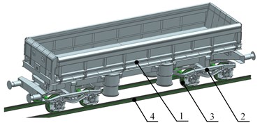
The considered object of investigations has the following characteristics: the length of 12,54 [m], width of 3.08 [m], height of 3.2 [m], wagon weight 27 000 [kg], loading capacity 31 [m3] payload 52 000 [kg].
The first step of investigations of the freight wagon was to create a model prepared for motion simulation. For this purpose, the “Motion Simulation” module of the system of the CAD/CAE/CAM class (Siemens PLM NX) [17-20] was used. The model, prepared to motion simulation, was created on the basis of a solid model, which imitates the geometrical form of the 418V dumping freight wagon. The model preparation consisted of defining: the objects of the “link” type (representing the geometrical form of particular components of the wagon); the objects of the “joint” type (specifying possible ways of movement mating between objects of the “link” type by receiving a certain number of degrees of freedom); objects of the “connectors” type (defining the nature of the contact between the wheels of the wagon and the rails). During creating the model, prepared for motion simulation, the following assumptions were made:
• all objects of the “link” type are perfectly rigid - they do not undergo a deformation,
• geometric objects, being a part of a single object of the “link” type, do not change its position in relation to other objects belonging to the same object of the “link” type,
• assumed model of the track maps its ideal state of the geometric form without deformation resulting from the manufacturing process and exploitation,
• the model of the track including its tilt,
• the wagon moves independently on the track, without regarding the contact with other wagons or a locomotive,
• a part of the track, which is a straight line, is designated to accelerate the wagon to the required speed value,
• the main motion analysis is carried out on the part of the track in the form of an arc.
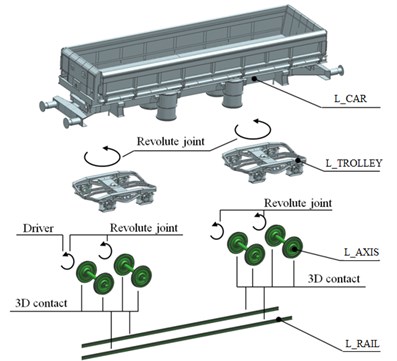
In the first developed model it was created 8 objects of the “link” type, 7 objects of the “joint” type and 16 objects of the “connectors” type. The first model, prepared to the motion simulation, contains the following groups of objects (Fig. 3). Objects of the “link” type:
• L_CAR – representing the geometrical form of the wagon box, with a frame and all elements which, during the movement, do not change their position relative to each other,
• L_RAIL – representing the geometrical form of the track on which moves the wagon,
• L_AXIS_WP_1, L_AXIS_WP_2, L_AXIS_WT_3, L_AXIS_WT_4 – representing the geometrical form of particular axles with wheels,
• L_TROLLEY_P, L_TROLLEY_T – representing the geometrical form of two-axle bogies 25TNa.
Objects of the „joint” type:
• J_Fix (fixed type) – defining the behaviour of the L_RAIL object by limiting him 6 degrees of freedom (restrain),
• J_AXIS_1_P, J_AXIS_2_P, J_AXIS_3_T, J_AXIS_4_T (revolute type) – defining the possible move between the objects L_AXIS_WP_1, L_AXIS_WP_2 and L_TROLEY_P and L_AXIS_WT_3, L_AXIS_WT_4 as well as L_TROLLEY_T by limiting three degrees of freedom associated with object translation and two degrees of freedom associated with object rotation (it provides the rotation of the bogie axis together with wheels in relation to the body of the bogie),
• J_TROLLEY_P-CAR, J_TROLLEY_T-CAR (revolute type) – defining the possible move between the objects L_TROLLEY_P, L_TROLLEY_T and L_TROLLEY (it provides the rotational move of bogies in relation to the wagon box).
Objects of the „connectors” type:
• G_STREIGHT_WHEELi-AXISj – 1..8, 1..4 (3D contact type) – defining the nature of the 3D contact between the objects L_AXIS_WP_1, L_AXIS_WP_2, L_AXIS_WT_3, L_AXIS_WT_4 and L_RAIL on a straight part of the track,
• G_ARC_WHEELi-AXISj – 1..8, 1..4 (3D contact type) – defining the nature of the 3D contact between the objects L_AXIS_WP_1, L_AXIS_WP_2, L_AXIS_WT_3, L_AXIS_WT_4 and L_RAIL on the section of track in the form of an arc.
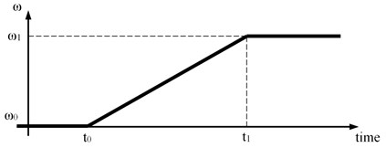
In order to introduce the extortion in the analysed system it was defined the object of the „driver” type, which was linked with the J_AXIS_1_P object of the „joint” type. This link allowed to apply the extortion force in the form of the angular velocity of the front axle of the wagon, on which are mounted wheels. The rotational movement of the bogie axle forced in this way, through the use of the objects of the 3D contact type between the track and wheels of the wagon, and the objects of the revolute type between the axles of the bogie and its body as well as the bogie body and the wagon box, is transferred into the linear movement of the whole wagon. The extortion, introduced to the system, is defined as follows (Fig. 2):
where – the beginning of the time interval in which the rotational speed of the L_AXIS_WP_1 object reach the value , – the end of the time interval in which the rotational speed of the L_AXIS_WP_1 object reach the value .
Between the value of the rotational speed related with the L_AXIS_1 object and the value of the linear speed of the moving wagon is the following relationship:
where – the radius of the L_AXIS_WP_1 object in the place of a contact with the L_RAIL object.
Fig. 2Graphical representation of the utilized extortion
To map the behaviour of the wagon running on a track way the objects of the 3D contact type were created. These objects characterize the way of mating between the wheels, included in the objects L_AXIS_WP_1, L_AXIS_WP_2, L_AXIS_WT_3, L_AXIS_WT_4 and rails belonging to the L_RAIL object. It was assumed that the wheels with axles and rails are made of steel with the following basic parameters: density 7.8·10-6 [kg/mm3], Young’s modulus 210 000 [N/mm2], Poisson ratio 0.3. On the basis of the documentation it was assumed that the created contact will be characterised by the following parameters: stiffness () 100000 [N/mm], stiffness exponent (m) 1.5, material damping () 50 [N.s/mm], penetration depth () 0.1 [mm], stiction velocity 0.1 [mm/s], friction velocity 10 [mm/s], static coefficient of friction 0.3, dynamic coefficient of friction 0.25. Basing on the presented parameters the model of 3D contact calculates the contact normal force ().
Normal force of the contact is expressed as the following relationship:
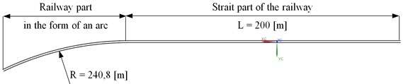
In order to accelerate the wagon to the required speed it should be created a straight section of the track with the length of 200 [m] (Fig. 4). The length of the acceleration part of the track is resulted from the assumption that the tested object moves independently along a track-way, wherein is only driven the front axle of the wagon (to the desired speed and then it is kept constant value during the motion on the arc-shaped raceway) according to the expression 1. Due to the occurrence of the slip between the wagon wheels and the rail, in the start-up phase, it was increased the static coefficient of friction and the dynamic coefficient of friction to the value that guarantees the target speed in the assumed period of time. It should be noted that these coefficients were changed only on the straight part of the track, and the move on the most dangerous part of the railway in the form of an arc took place in accordance with the previously adopted values of the parameters of the 3D contact object.
Fig. 3The model prepared for the motion simulation
In order to shorten the time necessary to increase the speed of the freight car to required value during the simulation the value of the friction coefficient was changed. On the straight part of the rail it was increased while on the rail in the form of an arc it had the standard value. The results of the second part of the simulation (while the modelled freight car was moving along the rail in the form of an arc) were the aim of the work. In this part values of all parameters such us damping, stiffness or friction coefficients were defined using values obtained from the real object.
Fig. 4Graphical representation of the railway
Firstly, it was realised the analysis of the movement of such elaborated model, without taking into account the carried load (Fig. 5). The simulations were performed taking into account the motion parameters listed in Table 1.
Fig. 5Exemplar results of the movement simulations of the wagon without the carried cargo: a) without derailment, b) the wagon derailment
a)
b)
Table 1The list of values of parameters related with the extortion (wagon without the cargo)
[km/h] | [s] | [s] | [°/s] | [°/s] | Simulation result |
70 | 0 | 15 | 0 | 2422 | Without derailment |
80 | 0 | 15 | 0 | 2768 | Without derailment |
90 | 0 | 15 | 0 | 3114 | Without derailment |
95 | 0 | 15 | 0 | 3287 | Without derailment |
100 | 0 | 15 | 0 | 3460 | Derailment |
Then it was analysed the wagon model with the carried cargo (Fig. 6). For this purpose, the object L_CAR has been modified and it was introduced the body with a volume corresponding to the volume of the cargo space, equal to 31 [m3]. It was assumed that the wagon is transported gravel with an average density of 1 650 [kg/m3]. It was obtained the value close to the maximal capacity of the wagon of 52 000 [kg]. For the model taking into account the carried load also a series of simulations, with regard to the parameters in Table 2 was conducted.
Table 2The list of values of parameters related with the extortion (wagon without the cargo)
[km/h] | [s] | [s] | [°/s] | [°/s] | Simulation result |
70 | 0 | 15 | 0 | 2422 | Without derailment |
75 | 0 | 15 | 0 | 2595 | Without derailment |
77 | 0 | 15 | 0 | 2665 | Without derailment |
78 | 0 | 15 | 0 | 2768 | Derailment |
Fig. 6Exemplar results of the movement simulations of the wagon with the carried cargo: a) without derailment, b) the wagon derailment
a)
b)
The obtained results of the analysis, on the basis of visual evaluation of derailing of the wagon, let to eliminate the ranges of speed values above which explicitly comes to wagon derailment from the track. However, with regard to the positive results of the simulation the level of safety of the wagon movement on the track in the form of an arc should be examined. Accordingly, in the work is assumed that in the cases in which there has been no explicit derailment, it should be calculated the index of derailment danger, shown in [21-23]. The authors of these works suggest that the safety of wagon movement on the track is dependent on the relationship of forces (Fig. 7), where force is described as a lateral, guiding one and the force is described as the force of a vertical pressure of a wheel on the rail. Due to the geometry of the rail head and existing components of friction forces between the wheel and the rail head, it is assumed that the movement of the wagon along the track is safe if the ratio < 0.78. Whereas this value is exceeded, it should be checked the vertical displacement of the wagon wheel, which should not be greater than 5 [mm].
Fig. 7Graphical representation of the guiding force Fy and the force of vertical pressure of the wheel on the rail Fz: a) safety case, b) danger case [comp. 4]
![Graphical representation of the guiding force Fy and the force of vertical pressure of the wheel on the rail Fz: a) safety case, b) danger case [comp. 4]](https://static-01.extrica.com/articles/19206/19206-img9.jpg)
a)
![Graphical representation of the guiding force Fy and the force of vertical pressure of the wheel on the rail Fz: a) safety case, b) danger case [comp. 4]](https://static-01.extrica.com/articles/19206/19206-img10.jpg)
b)
Due to the considered, in this work, the area of the problem, the more interesting object of investigations is the wagon carrying the cargo. Figs. 8 and 9 show diagrams which present the derailment index for the wagon with the transported load. In both presented cases, the value of this index is greater than the limit value. It could be seen that in the case of the wagon moving at the speed of 70 [km/h], the maximal value of the index is 1.2 and relates to wheel 4 moving on the outer rail on the arc (wheel1 3, 5, 7 the wheels moving on the internal rail, wheel 2, 4, 6, 8 the wheels moving on the outer rail). When the speed increased to 77 [km/h] maximal value of the ratio has increased to approx. 1.9 and relates to the same wheel. In the next step the displacement characteristics of the axle with wheel4 was examined. Fig. 10 shows that the characteristics of the wheel4 is within the range of the allowable displacement in the vertical axis (value referred to the reference value equal to 634 [mm] in the absolute coordinate system).
Fig. 8Values of the derailment index of the wagon at the speed equal to 70 [km/h]
![Values of the derailment index of the wagon at the speed equal to 70 [km/h]](https://static-01.extrica.com/articles/19206/19206-img11.jpg)
Fig. 9Values of the derailment index of the wagon at the speed equal to 77 [km/h]
![Values of the derailment index of the wagon at the speed equal to 77 [km/h]](https://static-01.extrica.com/articles/19206/19206-img12.jpg)
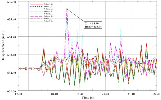
On the basis of the two criteria it could be assumed that the maximal safe speed value at which the investigated wagon with the cargo moves, on the arc-shaped track, is 77 [km/h]. It should be noted however that in the case of analyzing the movement of a wagon moving at high velocities, besides to the phenomenon of climbing the wagon wheel on the rail head is also dangerous the phenomenon of detachment of the wheels of the wagon moving on the inner rail due to the occurrence of a centrifugal force. Therefore, in the work it was decided to examine the course of the value of the force pressing the wagon to the rail. If the value of this force is equal to zero then the vertical movement of the wheels should be checked. In Fig. 11 it could be seen that at approximately 22 second of the movement the force is equal to zero. This means that the wheels 1, 3, 5, 7 of the wagon completely detached from the rail. This is illustrated in Fig. 12. The maximal displacement of the wheel in the vertical axis amounted to 25 [mm].
Fig. 10Displacement of the wheel4 in the vertical axis during the wagon movement on the arc at the speed equal to 77 [km/h]
![Displacement of the wheel4 in the vertical axis during the wagon movement on the arc at the speed equal to 77 [km/h]](https://static-01.extrica.com/articles/19206/19206-img13.jpg)
Fig. 11Course of variability of the pressing force Fz, V= 77 [km/h]
![Course of variability of the pressing force Fz, V= 77 [km/h]](https://static-01.extrica.com/articles/19206/19206-img14.jpg)
Fig. 12Vertical displacement of the wagon wheels, V= 77 [km/h]
![Vertical displacement of the wagon wheels, V= 77 [km/h]](https://static-01.extrica.com/articles/19206/19206-img15.jpg)
2.2. Modification of the model prepared for motion simulation
The next phase of the work included operations aimed the detailing of the virtual model of the wagon movement on the track way. For this purpose, the model prepared for motion simulation was complemented with the elastic elements. The introduced change forced also the remodelling of the same model (Fig. 13). In the analysed model an elastic element with a line characteristic was adopted:
where: – stiffness 1.107[N/m], , – displacements of the ends of the spring as a function of time.
Fig. 13Introduction of elastic elements to the virtual model
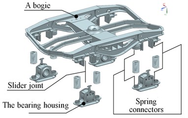
Reconstruction of the model, prepared for motion simulation, consisted of:
• Modification of the components L_TROLLEY_P and L_TROLLEY_T of the “link” type by extracting from them the additional components L_WP_K1, L_WP_K2, L_WP_K3, L_WP_K4, L_WT_K5, L_WT_K6, L_WT_K7, L_WT_K8,
• Creation of the components of the “joint” type J_L1_P, J_L2_P, J_L3_P, J_L4_P, J_L5_T, J_L6_T, J_L7_T, J_L8_T (slider type) - defining the possible move between objects L_TROLLEY_P and L_WP_K1, L_WP_K2, L_WP_K3, L_WP_K4 as well as L_TROLLEY_T and L_WT_K5, L_WT_K6, L_WT_K7, L_WT_K8 by fixing two degrees of freedom associated with the movement of the object and the three degrees of freedom associated with rotation of the object (it provides the reciprocating motion of the car body relative to the bearing housings on which are mounted wheel axles),
• Adding the components of the “connectors” type S_Ki_j ( 1 to 4; 1, 2) in the form of elastic elements - defining the nature of the interaction of components L_TROLLEY_P, L_TROLLEY_T and L_WP_K1, L_WP_K2, L_WP_K3, L_WP_K4, L_WT_K5, L_WT_K6, L_WT_K7, L_WT_K8.
For the modified wagon model, a cycle of motion simulation has been carried. Simulations were conducted in accordance with the previously described procedure for the speed values equal to 70 [km/h] no derailment, 75 [km/h] - no derailment and 77 [km/h] no derailment. Subsequently, the value of the wagon derailment index, at the maximal speed equal to 77 [km/h], has been determined. In the described case, the maximal value of the index amounted to 1.97 (Fig. 14). Accordingly, it was verified the vertical displacement of wheels which run on the outer rail. All values of vertical displacements of these wheels do not exceed the value of 7 [mm] (Fig. 15). Then it was verified the variation of the pressing force and the vertical displacements of all wheels (Fig. 16). On the basis of Fig. 17 it could be concluded that the maximal vertical displacement of the wheels was 8 [mm] with respect to the initial displacement equal to 634 [mm] in the absolute coordinate system.
The presented values of displacement of the wagon wheels exceed the required threshold of safety value equal to 5 [mm]. In order to mapping better the behaviour of the wagon during its motion on the railway the elaborated model has been further refined. Another providing of the model with details consisted of implementing a simplified model of friction in the suspension of wagon cars. It was assumed that the friction in the suspension of the car is a viscous one. Damping force is described in this case, with the linear equation:
where: – viscous damping coefficient, , – displacement velocities of damper ends as the function of time. In the calculations assumed viscous damping coefficient equals to 2.104 Ns/m.
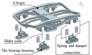
Another modification of the model, prepared for motion simulation, is the addition of the components of the “connectors” type D_Ki_j ( 1 to 4; 1, 2) in the form of damping elements - defining the nature of the interaction of components L_TROLLEY_P, L_TROLLEY_T and L_WP_K1, L_WP_K2, L_WP_K3, L_WP_K4, L_WT_K5, L_WT_K6, L_WT_K7, L_WT_K8 (Fig. 2.1.18).
Fig. 14Values of the index of wagon derailment at the speed equal to 77 [km//h] (the model includes elastic elements)
![Values of the index of wagon derailment at the speed equal to 77 [km//h] (the model includes elastic elements)](https://static-01.extrica.com/articles/19206/19206-img17.jpg)
Fig. 15Displacements wheel2, 4, 6 and 8 in the vertical axis during the wagon movement on the arc part of the railway at the speed equal to 77 [km//h] (the model includes elastic elements)
![Displacements wheel2, 4, 6 and 8 in the vertical axis during the wagon movement on the arc part of the railway at the speed equal to 77 [km//h] (the model includes elastic elements)](https://static-01.extrica.com/articles/19206/19206-img18.jpg)
Fig. 16Course of variation of the holding force Fz (the model includes elastic elements)
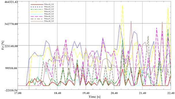
Fig. 17Vertical displacements of wagon wheels (the model includes elastic elements)
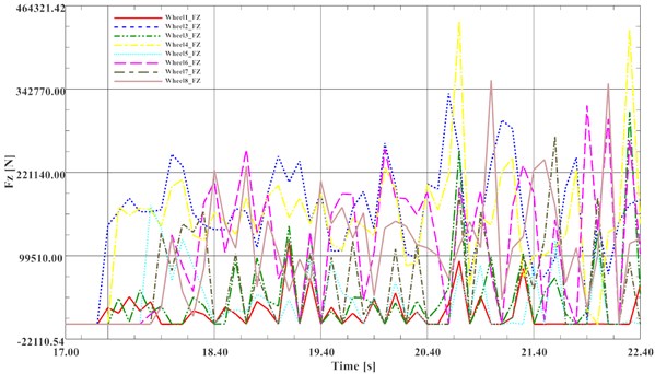
Fig. 18Introduction of dumping elements into the virtual model
The model of the wagon complemented with elastic-damping elements, was used to conduct a series of simulations. Simulations were conducted in accordance with the previously described procedure for the speed values equal to 70 [km/h] no derailment, 75 [km/h] no derailment and 77 [km/h] no derailment. Subsequently, the value of the wagon derailment index, at the maximal speed equal to 77 [km/h], has been determined. In the described case, the maximal value of the index amounted to 0.95 (Fig. 19). Accordingly, it was verified the vertical displacement of wheels which run on the outer rail. All values of vertical displacements of these wheels do not exceed the value of 2 [mm] (Fig. 20). Then it was verified the variation of the pressing force and the vertical displacements of all wheels (Fig. 21). On the basis of Fig. 22 it could be concluded that the maximal vertical displacement of the wheels was 2 [mm] with respect to the initial displacement equal to 634 [mm] in the absolute coordinate system.
3. Measurements of the real freight car’s vibrations during operation and their application in laboratory tests
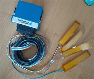
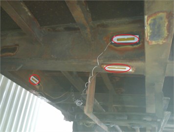
On the other hand, during the carried out research works, measurements of the real freight car’s elements vibrations during operation were carried out. The aim of this work was to verify about the possibility to infer about the technical condition of the modernized freight car on the basis of its elements’ vibrations analysis. Measurements of the real object were also used in the process of the CAD model validation. The object of the research was the four axial freight wagon of ordinary type Eaos 1415-A3. It was being taken into consideration because it is one of the most popular types of wagons. It was designed to be unloaded using tipplers. Measurements were carried out using analogue input card type NI-9215 [24] and portable device NI cDAQ-9191 [25] the compact 1-Slot chassis which allows Send data to a host PC over Ethernet or IEEE 802.11 Wi-Fi. As sensor M-8514-P1 model of Macro Fiber Composite transducer was used with active area 85×14 mm [26]. The analogue input card connected with four MFC piezoelectric sensors is presented in Fig. 23(a). In Fig. 23(b) the frame of the freight car with installed piezoelectric transducers is presented.
Fig. 19Value of the index of wagon derailment at the speed equal to 77 [km//h] (the model includes elastic-dumping elements)
![Value of the index of wagon derailment at the speed equal to 77 [km//h] (the model includes elastic-dumping elements)](https://static-01.extrica.com/articles/19206/19206-img22.jpg)
Fig. 20Displacements wheel2, 4, 6 and 8 in the vertical axis during the wagon movement on the arc part of the railway at the speed equal to 77 [km//h] (the model includes elastic-dumping elements)
![Displacements wheel2, 4, 6 and 8 in the vertical axis during the wagon movement on the arc part of the railway at the speed equal to 77 [km//h] (the model includes elastic-dumping elements)](https://static-01.extrica.com/articles/19206/19206-img23.jpg)
Fig. 21Course of variation of the holding force Fz (the model includes elastic-dumping elements)
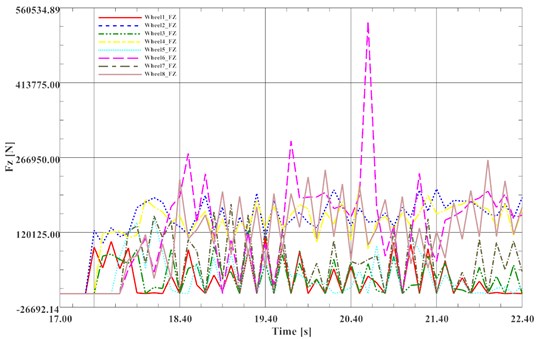
Fig. 22Vertical displacements of wagon wheels (the model includes elastic-dumping elements)
Four sensors were glued on the surface of the frame and body shell of the tested wagon and connected to the portable measurement system for data acquisition. Measurements were carried out while the observed train was driving (locomotive and two wagons) with the maximum travelling speed about 10 km/h. The speed of the train was limited as a result of the applicable regulations because measurements were carried out in the area of the railway repair company. There was no agreement to conduct research during normal exploitation. The train was driving a section of about 400 meters, stopped and then it was returning. The test was repeated five times to verify the repeatability of the results. Measurements were made in repair facility of DB Schenker Rail Poland in Rybnik. Measurement points were as:
• Channel 1 – the centre of the top band of the box, interior of the freight wagon;
• Channel 2 – the support frame – the bottom surface of the main, outer beam of the frame;
• Channel 3 – the support frame – the inner surface of the main, outer beam of the frame;
• Channel 4 – the support frame – side surface of the crossbeam.
Fig. 23a) The analogue input card connected with four MFC piezoelectric sensors, b) the frame of the freight car with installed piezoelectric transducers
a)
b)
Measuring points were selected on centre points of main beams of the wagon’s frame and on the centre of the top band of the box because it was predicted that deformation of surfaces of these elements of the wagon construction will be the biggest. This was important for the measurements using MFC piezoelectric foils glued on surfaces of these elements.
The main aim of the measurements was to acquire a profile of excitations that are elements of the freight wagon exposed to during exploitation of the wagon. This profile was in the next step used in tests using laboratory stands in order to verify their dynamical response onto the excitation occurring during operation. In Fig. 24 results of measurements obtained for the channel 4 are presented. The measured profile of excitations occurring during operation for empty wagon and maximal speed 10 km/h is presented. The red vertical line separates two operating ranges: in the first range the wagon was pulled by the locomotive, while in the second one the wagon was pushed by the locomotive.
It can be observed that the electric voltage generated by the piezoelectric MFC sensors has not a high value, but measured signal can be used in order to reproduce the extortion profile course during laboratory tests.
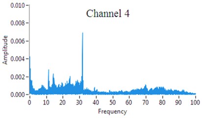
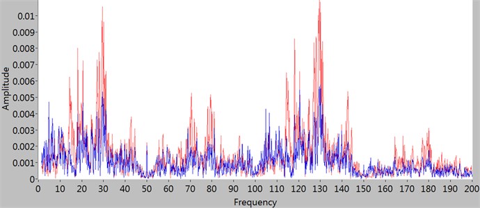
The measured signal was then analysed used Fast Fourier Transform to verify the resonance zones of the vibrating elements. An example of results of measured signal FFT analysis obtained using Hanning window is presented in Fig. 25.
Fig. 24The measured profile of excitations for channel 4 (empty wagon and max. speed 10 km/h)
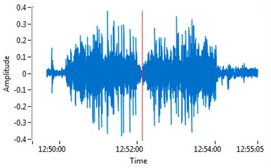
Fig. 25An example of results of measured signal FFT analysis
The carried out measurements proved that results are repetitive and can be used in laboratory tests. During all measurements it could be observed that obtained results are repeatable (taking into account range of possible measurement errors) for all tested measuring points without influence of the weather conditions and temperature. It can be concluded that Macro Fiber Composite piezoelectric transducers proposed as sensors in developed system could be successfully used. They have a lot of advantages which causes that they can be proposed as a very good solution, for example they can be easily applied to the structure by gluing it to its surface. They are produced in the form of thin foils, so they also can be easily laminated into the structure of the composite panels that will be mounted in the modernized freight wagons. What is more they are resistant to weather conditions and do not require additional power source. What is more, for a low frequencies measurments the store and hold amplifier can be used with the MFC transducers what can improve precision of measurements [26].
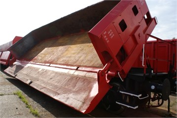
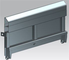
At the next step the measured profile of vibration excitation that is a result of the operation of the freight wagon was used for tests on a created laboratory stand. The laboratory stand was prepared for strength analysis of a side of a hopper freight wagon type 418V. This type of wagon is presented in Fig. 26(a). In Fig. 26(b) a CAD model of the tested piece of the freight wagon’s side is presented. In carried out measurements the laboratory stands for strength analysis of the 418V freight wagon side element was used. The side’s element was prepared in 1:2 scale.
During measurements the freight wagon’s side was excited using vibration test system produced by TIRA GmbH. As sensors also Macro Fiber Composite M-8514-P1 piezoelectric transducers were used and connected with analogue input cards and portable device NI cDAQ-9191 [24-26]. Measurements were carried out with and without composite panels mounted to the wagon’s side using rivet nuts. The aim of this work was to verify if it is possible to detect the presence of composite panels mounted to the tested wagon’s side element. The tested element was excited using electrodynamic shaker and vibration profile obtained during the measurements carried out on the real freight wagons. Vibrations of the analysed side were measured in four measuring points using MFC piezoelectric transducers. The MFC sensors were glued to the surfaces of the side’s frame as well as to the sheet metal fill. Measuring points were selected on centre points of main beams of the wagon’s side model and on the centre point of the composite panel. It was predicted that deformation of surfaces of these elements of the wagon’s side model will be the biggest.
Fig. 26a) The type of type 418V freight wagon, b) CAD model of the tested piece of 418V freight wagon’s side
a)
b)
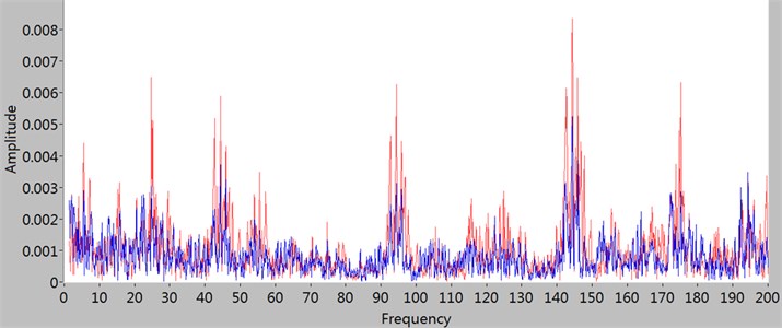
Fig. 27Results of the FFT analysis of measured signals juxtaposed for the system witch (the blue line) and without (the red line) composite panels for channel 1 (a) and channel 2 (b)
a)
b)
Results obtained for measuring points on the side’s frame and on the sheet metal fill for the wagon’s side model with and without composite panels are presented in this work. As the next step of the carried out analysis the Fast Fourier Transform of measured signals was carried out in order to verify if any change in the obtained results can be observed. Results of the FFT analysis of measured signals obtained for the system with and without composite panels are juxtaposed in Fig. 27 up to frequency 200 Hz. The red line denotes results obtained for the model of the freight wagon’s side without any additional element while the blue line denotes results for the model with composite panels. The panels were made of fiberglass and epoxy resin with thickness 6 mm. They were mounted using rivet nuts.
It can be noted that for both measuring channels the analysed system has higher values of the amplitude for all frequencies of vibrations in case when there is no composite panels mounted. Such results can be very useful for the algorithm that will be use in the system designed for modernized freight wagons technical condition monitoring during their exploitation. There may be a possibility to detect destruction of the mounted composite panels by the system on the basis of measured signals from applied piezoelectric foils. The system should also detect if the freight wagon is loaded or it is used empty and inform about its status using GPS system. Such information can be very useful for better managing of freight wagons and for data collecting in the system that should record the history of the wagons exploitation.
4. Conclusions
For the model of the wagon, prepared for motion simulation, which includes elastic - damping elements, the values of displacements of wheels in the vertical axis at the rate of 2 [mm] have been obtained. The resulting value is less than the threshold value treated as the safe one (5 [mm]). It is also possible to conclude that the resulting speed value is the safe one. It should be noted, however, that the elaborated model requires a further process of providing with details and identification of properties of the analysed object in the form of a freight wagon. Analysing the obtained results it could be stated that, by the appropriate selection of the parameters of the analysed system it has been obtained the reduction of vertical displacements of the wagon wheels, during their movement on the railway, from the level of 25 [mm], by 8 [mm] (the use of the elastic elements) to 2 [mm] (the use of elastic-damping elements). It should be emphasised that the presented investigations include results obtained for one particular value of speed of the wagon. Changes of the rigidity parameter of a spring and the damping coefficient caused that the system is characterised by less favourable properties (greater vertical displacements of wagon wheels). It has also been performed a cycle of simulating of wagon movement on the railway for larger values of movement speed using the previously chosen parameters of elastic-damping elements. During this tests it has been reached the value of speed of the moving wagon, being under consideration, of 90 [km/h] with no visual effects of derailment.
As the result of conducted investigations the value of the safe speed movement of the wagon transported a cargo on the track way equal to 77 [km/h] was obtained. The simplification, used in the work, in the form of the lack of a track way slope allows assuming that the adopted model provides a margin of the safe speeds. As the result of model detailing it was obtained the model with lower values of vertical displacements of the wagon wheels, at the same speed of movement of the wagon on the track in the form of an arc. In order to obtain a proper fit of operation of the virtual model to the real object the research aimed at identifying the real object properties should be continued.
Carried out tests and measurements on freight wagons as well as using laboratory stands proved that Macro Fiber Composite piezoelectric transducers can be successfully used as sensors for measurements of freight wagon’s elements vibrations. They can be easily applied to the surface of monitoring structure as well as laminated in composite panels that will be used during proposed freight wagons modernization. What is more they can be easily protected to weather conditions.
During carried out tests on the real freight wagon the speed was limited and it was lower than speed of a train during its standard exploitation. It caused that values of measured signals were lower than they can be predicted in application on freight wagons for standard operation. However, using measured profile of excitation it was possible to infer about the status of the laboratory stand. Taking into account obtained results of laboratory tests it was possible to conclude whether composite panels are connected to the tested model of the freight wagon’s side or they are lacked. Obtained results allow concluding that proposed method of control of technical condition of modernized freight wagons may be a good solution.
In further research more measurements on laboratory stands and especially on real objects during their standard exploitation will be carried out in order to verify repeatability of the obtained results and to take into account influence of various conditions such as weather conditions, deformations of the wagon’s body shell that are results of its exploitation, mainly unloading using excavators etc. The influence of changes in monitored system created during its exploitation appears as a main problem which may result in system malfunction.
The mathematical model of the object is always a very important part of the research work. Results obtained by mathematical analysis could be used as references for results of simulation. However, in the presented work the information obtained from the real object were used in the validation process of obtained results of simulation (maximum speed of the freight car on the rail in the form of an arc, damping and stiffness coefficients and so on). After introducing to the virtual model correct parameters from the real object, the model could be adjusted ant the results obtained in simulation were consistent with the parameters of real objects and satisfying. Mathematical model of the freight car was presented for example by Rae V. Dukkipati in the book “Vehicle dynamics” [27]. The author presents also the mathematical model of the freight car with load. In the future works obtained results of simulations carried out in virtual environment will be juxtaposed with the results of the numerical calculations and presented in other publications.
References
-
Hecht M. Wear and energy-saving freight bogie designs with rubber primary springs: principles and experiences. Proceedings of the Institution of Mechanical Engineers Part F: Journal of Rail and Rapid Transit, Vol. 223, Issue 2, 2009, p. 105-110.
-
Oleszak P., Ciesla J., Szaniec W. Study of the effects of side impacts on railway viaduct lying on the arc. Budownictwo i Architektura, Vol. 12, Issue 2, 2013, p. 47-54, (in Polish).
-
Stypula K. Selected problems of surface building protection against vibrations generated by underground communication. Gornictwo i Geoinzynieria, Vol. 3, Issue 1, 2009, p. 351-362, (in Polish).
-
Herwig A., Bruhwiler E. In-situ dynamic behaviour of a railway bridge girder under fatigue causing traffic loading. Proceedings of the 11th International Conference on Applications of Statistics and Probability in Civil Engineering, Zurich, Switzerland, 2011, p. 389-395.
-
Mehrpouya M., Ahmadian H. Estimation of applied forces on railway vehicle wheelsets from measured vehicle responses. International Journal of Vehicle Structures and Systems, Vol. 1, Issue 4, 2009, p. 104-110.
-
Grebowski K., Zielinska M. Modelling of dynamic interactions of Pendolino train type on structures of historic railway bridges in Poland. Przeglad Budowlany, Vol. 1, Issue 1, 2015, p. 27-32.
-
Bruni S., Vinolas J., Berg M., Polach O., Stichel S. Modelling of suspension components in a rail vehicle dynamics context. Vehicle System Dynamics, Vol. 49, Issue 7, 2011, p. 1021-1072.
-
Connolly D. P., Kouroussis G., Giannopoulos A., Verlinden O., Woodward P. K., Forde M. C. Assessment of railway vibrations using an efficient scoping model. Soil Dynamics and Earthquake Engineering, Vol. 58, Issue 1, 2014, p. 37-47.
-
Jönsson P. A., Stichel S., Persson I. New simulation model for freight wagons with UIC link suspension Vehicle System Dynamics, Vol. 46, Issue 1, 2008, p. 695-704.
-
Kovalev R., Lysikov N., Mikheev G. et al. Freight car models and their computer-aided dynamic analysis. Multibody System Dynamics, Vol. 22, Issue 4, 2009, p. 399-423.
-
Baier A., Zolkiewski S. Initial research of epoxy and polyester warp laminates testing on abrasive wear used in car sheathing. Eksploatacja i Niezawodnosc – Maintenance and reliability, Vol. 15, Issue 1, 2013, p. 37-43.
-
Wrobel A., Placzek M., Buchacz A., Majzner M. Study of mechanical properties and computer simulation of composite materials reinforced by metal. International Journal of Materials and Product Technology, Vol. 50, Issues 3-4, 2015, p. 259-275.
-
Buchacz A., Baier A., Świder J., Jamroziak K., Majzner M., Żółkiewski S., Wróbel A. Experimental Tests of Chosen Fibre-metal Laminates. Silesian University of Technology Press, Gliwice, 2012.
-
Placzek M., Wrobel A., Baier A. Computer-aided strength analysis of the modernized freight wagon. IOP Conference Series-Materials Science and Engineering, Vol. 95, Issue 1, 2015, p. 12042.
-
Placzek M., Buchacz A., Wrobel A. Use of piezoelectric foils as tools for structural health monitoring of freight cars during exploitation. Eksploatacja i Niezawodnosc – Maintenance and Reliability, Vol. 17, Issue 3, 2015, p. 443-449.
-
Buchacz A., Baier A., Herbuś K., Majzner M., Ociepka P. Investigation of motion of a freight wagon aimed to identify the forces acting on the side wall of the wagon. Dynamical Systems: Mechatronics and Life Sciences, ARSA Łódź, 2015, p. 77-88.
-
Gwiazda A., Herbuś K., Kost G., Ociepka P. Motion analysis of mechatronic equipment considering the example of the Stewart platform. Solid State Phenomena, Vols. 220-221, Issues 1, 2015, p. 479-484.
-
Banaś W., Gwiazda A., Herbuś K., Kost G., Ociepka P., Reclik D. Analysis of the dynamic properties of the mechatronic integrator of control procedures of the vehicle driven by persons with disabilities. Solid State Phenomena, Vols. 220-221, Issues 1, 2015, p. 3-8.
-
Banaś W., Herbuś K., Kost G., Nierychlok A., Ociepka P., Reclik D. Simulation of the Stewart platform carried out using the Siemens NX and NI LabVIEW programs. Advanced Materials Research, Vol. 837, Issue 1, 2014, p. 537-542.
-
Dymarek A., Dzitkowski T., Herbuś K., Kost G., Ociepka P. Geometric analysis of motions exercised by the Stewart platform. Advanced Materials Research, Vol. 837, Issue 1, 2014, p. 351-356.
-
Matej J. Simulation method for assessing the level of danger of derailment of a freight wagon on a straight track. Przeglad Mechaniczny, Vol. 1, Issue 1, 2011, p. 20-25, (in Polish).
-
Matej J. Modeling and Simulation Studies of Bimodal Wagons in Terms of Risk of Derailment. Science works: Mechanics, No 234. Publishing House of Warsaw University of Technology, Warsaw 2010, (in Polish).
-
Dusza M., Zboiński K. Accurate determination of critical speed of a rail vehicle model - comparison of methods. Czasopismo Techniczne. Mechanika, Vol. 109, Issue 14, 2012, p. 71-80, (in Polish).
-
National Instruments: Test, Measurement, and Embedded Systems, 2018, http://www.ni.com/pdf/manuals/373779a_02.pdf.
-
National Instruments: Test, Measurement, and Embedded Systems, 2018, http://www.ni.com/datasheet/pdf/en/ds-371.
-
Smart Material Corporation, 2018, http://www.smart-material.com/MFC-product-main.html.
-
Dukkipati R. V. Vehicle Dynamics. Narosa Publishing House, New Delhi, 2000.
About this article

Andrzej Buchacz – project manager, supervisor of the research works. Andrzej Baier – supervisor of the research works, scientific consultations. Marek Płaczek – development of the idea of the system for freight cars technical condition analysis, measurements of the freight car’s vibrations during operation and laboratory tests, editing of the article. Krzysztof Herbuś –preparation of the CAD models, analysis of the models motion in virtual reality, analysis of results and editing of the article. Piotr Ociepka – preparation of the CAD models, analysis of the models motion in virtual reality, analysis of results and editing of the article. Michał Majzner – preparation of the CAD models, analysis of the models motion in virtual reality.
