Abstract
The wide group of large engineering constructions made from welded metal components and modern composite materials during daily exploitation under non-stationary loads, continuous influence of vibrations and complicated environmental conditions have demand of periodical tests in order to avoid appearance and evolution of the defects. All of them have one common feature – large areas to be tested and the complex geometry. The objective is to improve air-coupled and contact type testing techniques for excitation and reception of appropriate modes of ultrasonic guided waves in large and complex structures. Also, to develop inspection techniques which enable to detect required types of internal defects. The air-coupled and contact ultrasonic techniques for investigation of large and complex geometry objects, such as composites for aerospace applications and petroleum tanks, have been developed. The investigation of propagation effects of ultrasonic guided (Lamb) waves in the plates of the tank floor has indicated relation between reconstructed properties of guided waves and expected presence of corrosion deposits.
1. Introduction
The significant group of large engineering constructions are made from welded metal components, novel composite samples, such as fibre reinforced metal laminates, honeycomb cores, carbon and glass fibre reinforced plastics. Engineering structures during exploitation under non-stationary loads, continuous influence of vibrations and complicated environmental conditions have demand of periodical tests in order to avoid appearance and evolution of the defects, like corrosion, disbonds, delaminations, breakage of fibres etc. All of them have one common feature – large areas to be tested and complex geometry.
One of the main non-destructive testing (NDT) techniques enabling to detect the defects during manufacturing operations or in-service periodical inspection is based on application of ultrasonic low frequency guided waves which propagates long distances in planar or tubular structures [1-3]. Such waves could be generated and picked-up by appropriate ultrasonic transducers: air-coupled or contact type [1, 2]. The inspection of composite aerospace materials, like segments of wings and covering panels, requires one-side access. Usually, access from the both sides is not possible. Some of objects should be additionally prepared before inspection, for example, the inspection of oil products storage tanks is sufficiently time consuming and costly procedure, mainly due to requirement to empty and to clean the interior of the tank before the testing procedure starts. Common problems for all these applications of guided waves are essential losses of it in the materials of the tested structures and complicated waveforms of received ultrasonic signals.
The objective of the work presented is to apply air-coupled and contact type testing techniques for excitation and reception of appropriate modes of ultrasonic guided waves in large and complex geometry engineering structures. Also, to develop appropriate inspection techniques which enable to detect required types of internal defects.
2. Air-coupled examination of the composite based materials having complex geometry
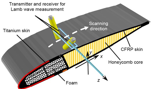
Main problems met during air-coupled ultrasonic examination and non-destructive testing (NDT) are due to curvature of the sample surface and low signal to noise ratio. In this case of non-contact application the Lamb waves technique requires that the orientation angles of transmitting and receiving ultrasonic transducers should correspond to the optimal angles for excitation and reception the asymmetric mode of Lamb waves at each scanning step [4]. In the case of composite materials investigations using such technique the losses of ultrasonic signal being received are sufficiently high, up to 130 dB. The main reason is due to high mismatch of acoustic impedances between the air and composite materials. Experimental set-up used for investigation of helicopter blade is presented in Fig. 1(a). The structure consists of carbon fibre reinforced plastic (CFRP) skin of shells and trailing edge, titanium skin of the leading edge, foam fillings and honeycomb core. The expected defects are delamination and disbond type defects in layers of skin and glued regions between skin and honeycomb or foam filling. The low frequency measurement and testing system developed at Ultrasound Institute (Kaunas University of Technology) with the 4 axes mechanical scanner was adapted for implementation of testing solution. The high sensitivity air-coupled transducers (central frequency 500 kHz, bandwidth 200 kHz) with the transduction loses of 50 dB were designed for this purpose to generate and receive Lamb waves [5]. The obtained ultrasonic B-scan image of the scanned defect-free region between titanium and carbon fibre reinforced plastic skins is presented in Fig. 1(b).
Fig. 1Investigation of the curved surface of the helicopter blade sample using Lamb waves: a) experimental set-up, b) ultrasonic B-scan image of the region between titanium and carbon fibre reinforced plastic (CFRP) skins
a)

b)
The image shows amplitudes and arriving time of the received signals at each scanning point, the scanning was performed along the distance of 60 mm and step of 1 mm (Fig. 1(a)). In the case of presence of the internal delamination or disbond type defect, the reduction of amplitudes over the particular region would occur.
3. Application of the contact type investigation of welded steel plates of the tank floor
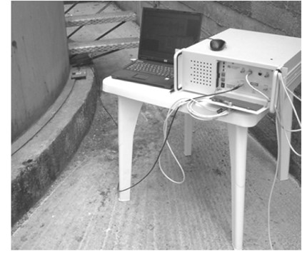
In order to avoid the leakage and pollution of the environment, detection of defective by corrosion areas in a floor of the fuel tank is very important task of ultrasonic examinations and NDT in petrochemical sector. The transmission tomography of propagating ultrasonic Lamb waves was selected as promising technique for investigation of the fuel tank floor [6-8]. Application of tomography method enables to reconstruct the spatial distribution of informative physical parameters of the object under investigation making influence to waves propagation. In the presented case, the spatial distribution of attenuation of the symmetric mode of Lamb waves is necessary to be reconstructed. As attenuation is related to presence of corrosion, the corroded regions will be indicated by higher attenuation. In order to test reliability of the developed algorithm, experimental investigations have been performed on a real petroleum tank having diameter of 8 m, filled with oil product (diesel), up to 1 m above the floor (Fig. 2(a)). The principle of tomography is based on set of measurements of transmitted Lamb waves across the welded floor of the tank at different reception angles in order to obtain projections.
The transmitter was fixed on one side and the ultrasonic signals of propagated Lamb waves (across the tank) were registered by the receiver attached at different positions on the opposite side of the tank. The step between neighbouring positions around the edge of the floor was 25 cm.
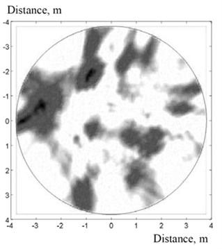
Fig. 2Application of the ultrasonic tomography (transmission) for investigations of real tank floor: a) experimental set-up, b) reconstructed distribution of Lamb waves attenuation inside welded floor of the petroleum tank
a)
b)
The number of projections for tomography reconstruction was 9 and each of the mentioned projections covers approximately 180° sector. In the experiments, the contact type ultrasonic transmitting and receiving transducers having the main frequency of 50 kHz were tested. For excitation and reception of guided waves the same previously mentioned ultrasonic examination system has been used. The ultrasonic transmitting transducer was excited by burst of 3 periods and the rectangular shape. During analysis of the acquired signals, filtering and selection of the propagating mode was performed. Such mode is being transmitted through the tank floor as a fastest due to highest propagation velocity. In order to reconstruct the spatial distribution of attenuation the amplitudes of the received mode and the backprojection algorithm were used.
The obtained spatial distribution of the measured attenuation of the mode of Lamb waves propagating in the welded floor of the real fuel tank is presented in Fig. 2(b) and the expected large corrosion areas correspond to the darker colour. Usually, the obtained resolution of reconstruction depends on quantity of tomographic projections and the presented example was reconstructed using only 9 projections.
4. Conclusions
The air-coupled and contact ultrasonic techniques for investigation of large and complex geometry objects by means of ultrasonic guided waves have been developed. The first group of investigated objects were multi-layered and complex geometry composites for aerospace application. It is possible to declare that the proposed technique is suitable to be applied for fast detection of the internal structural defects in the composite based constructions at their installation places (e.g. aircrafts).
The second group of investigated objects were welded steel plates of petroleum tank floor. The ultrasonic examination technique for inspection of the welded tank floor based on the application of transmission tomography of guided waves (the mode of Lamb waves) and contact type ultrasonic transducers has been developed. Such technique does not require pumping fuel out, cleaning interior of the tank what is very expensive, time consuming, and the tank is out of service during inspection. The investigation of transmitted Lamb waves along welded steel plates of the tank floor has demonstrated close relation between reconstructed properties of guided waves and location of corroded areas. Evaluation of the losses of propagating guided waves enables to predict that ultrasonic examination can be performed on tanks having diameter up to 30 m.
References
-
Cawley P., Alleyne D. N. The use of Lamb waves for the long range inspection of large structures. Ultrasonics, Vol. 34, Issue 2, 1996, p. 287-290.
-
Cawley P., Lowe M. J. S., Alleyne D. N., Pavlakovic B., Wilcox P. Practical long range guided wave testing: Application to pipe and rail. Material Evaluation, Vol. 61, Issue 1, 2003, p. 66-74.
-
Chimenti D. E., Rokhlin S. I. Relationship between leaky Lamb modes and reflection coefficient zeroes for a fluid-coupled elastic layer. The Journal of the Acoustical Society of America, Vol. 88, Issue 3, 1990, p. 1603-1611.
-
Kazys R., Demcenko A., Zukauskas E., Mazeika L. Air-coupled ultrasonic investigation of multi-layered composite materials. Ultrasonics, Vol. 44, Issue 1, 2006, p. 819-822.
-
Kazys R., Vladisauskas A., Zukauskas E. Wideband air-coupled ultrasonic transducers. Ultrasound, Vol. 3, Issue 52, 2004, p. 21-28.
-
Kazys R., Mazeika L., Barauskas R., Raisutis R., Cicenas V., Demcenko A. 3D analysis of interaction of Lamb waves with defects in loaded steel plates. Ultrasonics, Vol. 44, Issue 1, 2006, p. 1127-1130.
-
Mažeika L., Kažys R., Raišutis R., Demčenko A., Šliteris R. Long-range ultrasonic non-destructive testing of fuel tanks. DGZfP Proceedings BB 103-CD of ECNDT 2006, 2006, p. 1-8.
-
Mazeika L., Kazys R., Raisutis R., Sliteris R. Ultrasonic guided wave tomography for the inspection of the fuel tanks floor. International Journal of Materials and Product Technology, Vol. 41, Issues 1-4, 2011, p. 128-139.
Cited by
About this article

