Abstract
Ensuring the reliability and durability of machinery and equipment, and above all, protecting people and the environment from the damaging effects of generated vibrations. This requires the use of effective methods and measures to counter their formation or spread. The vibroactivity of a machine (device) treated as an object can be changed in two basic ways. Parametric or structural modifications can be made. This study investigates the effect of on off temporary of shock absorber on vehicle suspension for vibration isolation.
1. Introduction
Parametric modifications consist in changing the construction parameters of the object or the parameters of the forces acting on the object. Most often, they relate to structural parameters such as inertia and stiffness of components and dampening in motion connections. The change of vibroactivity through structural modifications can be realized in two ways. The first is to attach to the object mounted on the base additional elements (dynamic vibration eliminators). The second method of structural modification is to introduce between the object and the substrate of the additional element. The construction of the vibration isolation system is based on the selection of the vibration isolator so that the frequency of the vibration object's own vibration frequency is different from that of the external force spectrum [1-3]. The purpose of the research was to determine the effect of temporary suspension vibration damping on the vibroactivity of the object.
2. Assumptions of research
Changes in vibration isolation properties are achieved by varying the frequency of system vibration. The range of vibration isolation is the wider the lower the frequency of the system's vibration. Introducing vibration-limiting resonance damping reduces the vibration isolation properties. This is a major disadvantage of passive vibroinsulation systems. In addition, for mobility vibration isolation, the system should meet the following conditions:
– the relative displacement of the vibration isolation object should be less than the permissible value (due to static deflection)
– the object should be insulated from kinematic constraints (minimum acceleration, velocity or displacement), i.e. soft.
Such tasks, which should meet the system of vibration isolation, are contradictory and practically impossible to obtain in passive systems.
The vibration object of a given mass has a control force . This force is produced by a vibration isolator for which the vibration parameters of the vibration isolation system are input signals. Control force is the sum of the weight of the elastic force and damping force. These components of the control force are proportional to relative displacement and relative velocity, respectively. Proportional coefficients are the coefficients of elasticity and damping of the vibration isolator, respectively. The task of improving vibration isolation is to select the elasticity and attenuation coefficients to obtain the desired vibration transfer characteristic. Because of the negative impact of vibration damping on the vibration of the object caused by the non-resonance force, it is assumed that the temporary damping of the system will have a positive influence on the vibration transfer function [1, 4]. The following assumptions were made:
– two-tone suspension model will be used for the tests,
– damper damping characteristics will be nonlinear and will correspond to the actual damping characteristics,
– the developed system will be able to work as a classic passive suspension and as a system with damping control.
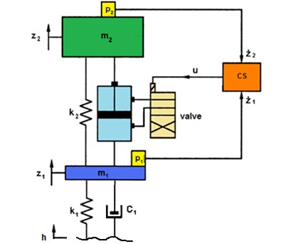
The diagram of the proposed vehicle suspension model together with the controls is shown in Fig. 1.
Fig. 1Diagram of suspension model with controlled vibration damper. m2 – sprung mass, m1 – unsprung mass, k1 – stiffness of wheel, k2 – stiffness of suspension, c2 – damping of suspension, c1 – damping of wheel, h – excitation, z2 – vertical displacement of sprung mass, z1 – vertical displacement of wheel, p1, p2 – velocity sensor, cs – controller
In the classic passive suspension system, the shock absorber can only draw energy from the system (converts mechanical vibration to heat). However, if the unpaved mass speed is greater than the speed of the sprung mass (in the indicated direction), the damping force is the force of mass acceleration . The developed algorithm of damping control consists in switching off the damper then affects the acceleration of the object of vibration insulation - the mass of the sprung. This means in practice that when speed vectors of sprung and unmade masses have identical expressions and the absolute value of the unpaved mass speed is greater than the absolute value of the sprung mass, damping is switched off. In all other cases, the velocity vector vectors and the damper damping force is the component of the vibration damper force. In order to avoid jitter shifting, the damping force occurs when the relative speed is zero. The jump parameter change is realized by disconnecting and restoring the constraints, i.e. by changing the structure of the system, i.e. it is a semi-active vibration system with variable structure.
3. Simulation verification of vibration damper model assumptions
The vibration isolation evaluation is based on the transfer function defined as the ratio of the vibrational response of the object to the acting force. Values of the transfer function less than unity mean that the vibration is good. The suspension model adopted for the study was implemented in MATLAB's SIMULINK environment. In the case of operation when the control is off, the shock absorber characteristics are nonlinear and asymmetrical [5-8].
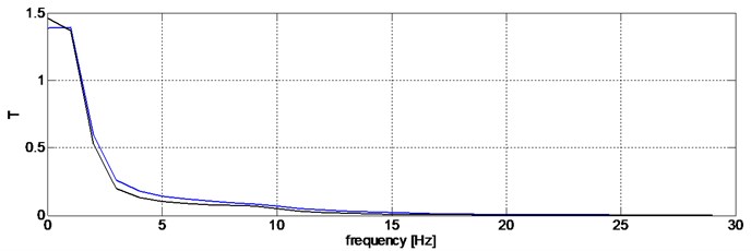
The transfer function has been used to evaluate the performance of a variable-displacement shock absorber. Figs. 2-5 show a comparison of the transition function with the shock absorber on and off control unit.
Fig. 2Transition functions defined for displacements of sprung and unsprung masses (blue color – driver disabled, black – damping characteristic adjusted)
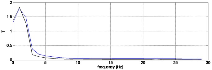
Fig. 3Transition functions determined for the displacement of the sprung mass against the ground (blue color – driver switched off, black – damping characteristic adjusted)
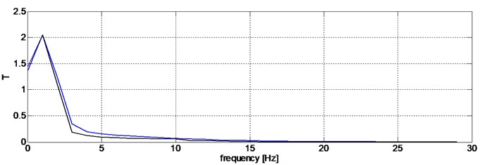
Fig. 4Transition functions defined for accelerations of sprung and unsprung masses (blue color – driver disabled, black – damping characteristic adjusted)
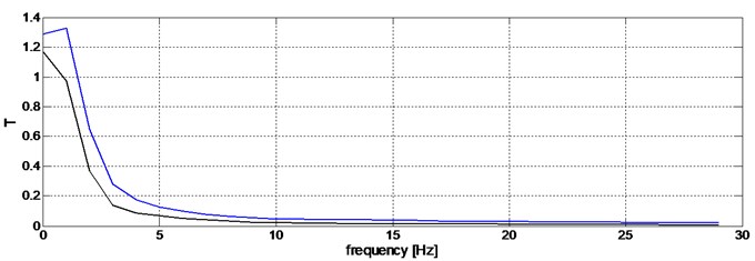
Fig. 5Transition functions determined for the accelerations of the sprung mass against the ground (blue color – driver switched off, black – damping characteristic adjusted)
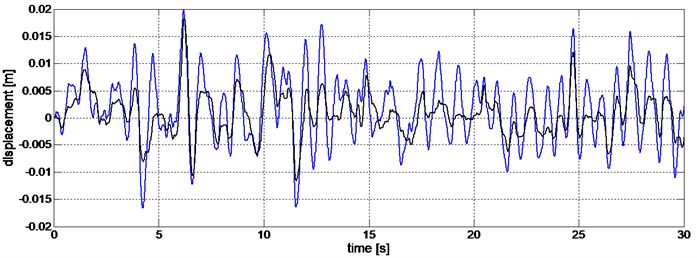
Significant improvement in the quality of suspension of the sprung mass is evident at the random forces. The studies used to enforce compliance with the ISO inequality profiles. An example of body vibration comparison for random extraction is shown in Fig. 7.
Fig. 6Comparison of vibration displacements of the sprung mass for forced random type (blue color – Driver switched off, black – Driver on)
4. Conclusions
The vibration damper tested is a discontinuous damper. Its functionality allows it to be used as a standalone component that can be used interchangeably in passive suspension systems. The mounting points for the sensors should coincide with the shock absorbers for the suspension and the body. It is then possible to obtain a compact shock absorber. These results confirm the performance of the damper with adjustable characteristics. The further aim of the work will be to prepare the prototype and its research on a real object.
References
-
Karnopp D., Crosby M. J., Harwood R. Vibration control using semi-active force generators. Journal of Engineering for Industry, Vol. 96, Issue 2, 1974, p. 619-626.
-
Rakheja S., Sankar S. Vibration and shock isolation performance of a semi-active “on-off” damper. Journal of Vibration, Acoustics, Stress, and Reliability in Design, Vol. 107, 1985, p. 398-403.
-
Gardulski J., Warczek J. Suspension research in the aspect of travel safety. Telematics and transport safety, 2006.
-
Shida N., Ye Z., Yong W., Konghui G. Velocity and displacement-dependent damper: A novel passive shock absorber inspired by the semi-active control. Mechanical Systems and Signal Processing, Vol. 99, Issue 15, 2018, p. 730-746.
-
Warczek J. Application of time shift for nonlinear damping characteristic identification. Transport Problems, Vol. 4, Issues 3-2, 2009, p. 91-96.
-
Dixon C. J. The Schock Absorber Handbook. John Wiley & Sons, Ltd., 2007.
-
Warczek J., Burdzik R., Peruń G. The method for identification of damping coefficient of the trucks suspension. Key Engineering Materials, Vol. 588, 2014, p. 281-289.
-
Warczek J., Burdzik R. Visco-elastic model of dynamic of hydraulic damper as a basis for determining the measurement condition. Scientific Papers of Transport. Silesian University of Technology, Issue 66, 2010.
About this article

