Abstract
The paper presents the proposed methodology of crankshaft stiffness matrix modeling. Geometry and linear-elastic shaft properties are one of common occurrences of torsionally rigid vibration coupling in crank systems. Model and experimental studies require the stiffness of the object in question. In the case of linear-elastic systems it is identical with the definition of its stiffness matrix. In the introduction, the current state of knowledge in the field of identification and modeling of crankshaft dynamics was reviewed. The next chapter presents the research stand for the study of dynamic properties of crank systems. The measurement path was described, its parameters and preliminary results were presented. The next part concerns the dynamic model of the crank system used by the authors and the need for a methodology to determine the stiffness of the shaft in question. The following chapters describe the mathematical description of the proposed methodology and the results of the calculations. The article was finalized with a summary of conclusions drawn from the work carried out.
1. Introduction
In the combustion engine, the crankshaft torsional vibration reduction is the most effective. This is dictated by fatigue strength of the shaft itself and care about the viability of the remaining components of the drive system. At the design stage of the structure with rotating elements, the problem of the bending and torsional vibration is very often overlooked and the vibrations are independently analyzed [1]. This is caused by a large complexity of the problem. Previous studies (also conducted by the authors) indicate that this is an important simplification [2]. Matrices of stiffness in commonly used models of uncoupled bending and torsional vibrations have a different form than those derived from numerical analysis. Qualitatively, other results are obtained for the linear-elastic crankshaft model [3]. The geometry of the object under consideration and its material properties are responsible for the coupling of its angular and transverse movements. Consequently, it was necessary to develop an effective methodology for determining the components of the crankshaft rigidity matrix. In addition, the analysis of the model proposed in [2] makes it possible to claim that the coupling phenomenon is useful for the purpose of diagnostic and structural rotor devices, in which the measurement of torsional vibrations is hindered by the use of coupling to induce torsional vibrations based on transverse vibrations which are easier to measure.
2. Test stand
The considered object is the crankshaft of the turbocharged twin-cylinder FIAT TwinAir with a displacement of 875 cm3 and a power of 63 kW (Fig. 1). The construction uses a balancer shaft driven by the crankshaft with a gear. The shaft is supported on three plain bearings.
The shaft was made of steel with forging technology. It is unified, has four counterbalance, flywheel attachment pins, oil pump drive, camshaft sprocket, and crankshaft that drive the rest of the engine.
The measuring system consists of a National Instruments measurement card, a computer with LabView software installed (analyzer and data logger), two triaxial piezoelectric accelerometers Brüel & Kjær, and one-axis piezoelectric accelerometer Brüel & Kjær for measuring the angle of the flywheel. The setup of the measurement system and the location of the transducers are shown in the diagram (Fig. 2).
Fig. 1Test stand – TwinAir two-cylinder engine with 875 cm3 displacement
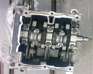
Fig. 2Diagram of test stand. 1. Sensor, 2. Flywheel, 3. Crankshaft, 4. Measure card, 5, PC
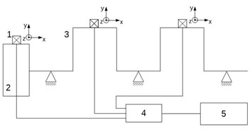
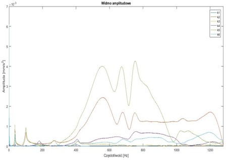
Fig. 3Results of experiments
3. Dynamic model of the crankshaft system
Based on the results of the previous work of the authors, a discreet linear-spring crankshaft model was taken. This is an important simplification for a continuous model characterized by infinite number of oscillation frequencies and vibration forms. In addition, the continuous model does not neglect vibration coupling. Despite the simplicity, the used model can be effective. The proposed approach allows for accurate mapping of important vibration frequencies and keeping of the torsion-bending coupling. The mathematical model in the matrix form is as follows:
here: – generalized coordinate matrix, – mass matrix, – damping matrix, – stiffness matrix, – nonlinear forces matrix, – forced forces.
The following six generalized coordinates are assumed for calculations: the angle of twisting of the shaft origin , the tangential displacement and normal of the shaft axis on both crank pins and the angle of twist of the shaft end . Based on the accepted data, the mass and gyroscopic forces were determined. The stiffness matrix of the general form remains to be determined:
As already noted in the introduction to the article, the model used in practice does not produce satisfactory results, which results in the occurrence of significant phenomena in the results of the simulation.
4. Mathematical model of crankshaft stiffness
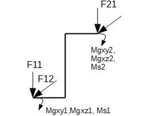
Determination of the stiffness matrix for linear-elastic systems is reduced to defining the significant nodes of an object in the directions of generalized forces. For simplicity of the model, it was decided to replace the complex geometry of the shaft with the simple beam diagram shown in Fig. 4. The diagram shows the directions of forces and moments operating on the shaft during operation.
Fig. 4Scheme of generalized coordinates and load distribution
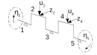
Fig. 5Finite element load diagram
In order to determine the stiffness matrix, an approach was proposed to determine the stiffness matrix fixed at one end (easy to experimentally verify) and transform it into a global stiffness matrix. Mathematical log of the algorithm is as follows:
where: – vector of the external forces, – vector of the reaction forces, – stiffness matrix of the walled element, – fixed system deflection vector, – matrix of node displacement geometry, – stiffness matrix in a global coordinate system, – vector of generalized displacements, – reaction force matrix depends on reaction force vector, – vector of the nodal forces.
In order to increase the generality of the proposed method of determining the crankshaft stiffness matrix, it was decided to build a specialized beam element in the form of a flat frame loaded with forces and moments as in the Fig. 5.
For the frame of Fig. 5, the stiffness matrix is determined:
After applying the dependence Eqs. (3-10) for matrix of the given Eq. (11), the stiffness matrix of the proposed finite element is obtained:
Taking into account the boundary conditions corresponding to the crankshaft support conditions, it is possible to determine the desired crankshaft rigidity matrix:
As can be seen, the stiffness matrix Eq. (13) determined with the use of the proposed methodology corresponds to the structure of the postulated general form of the crankshaft stiffness matrix Eq. (2).
Fig. 6Results of simulations

Fig. 6 shows the amplitude spectrum of:
– torsional vibrations of the shaft outset – fi1,
– torsional vibrations of the shaft end – fi2,
– bending vibrations of the first crank – un1,
– torsional vibrations of the first crank – ut1,
– bending vibrations of the second crank – un2,
– torsional vibrations of the first crank – ut2.
On the Fig. 6 torsional vibrations can be observed below 1000 Hz. Above 1000 Hz there are bending vibrations.
5. Conclusions
The paper presents the proposed methodology of crankshaft stiffness matrix modeling. In the first chapter, the problem of the dynamics of the crank systems and their vibration modeling was briefly characterized. The second chapter presents a test stand and gives relevant information. The next part presents the dynamic model used by the authors. In addition, the problem of determining the stiffness of the crankshaft matrix was formulated. Next, the proposed methodology for stiffness matrix determination is described. Calculations were made for a crankshaft case with relatively simple geometry. The fifth chapter presents the preliminary results of the simulation and experimental research.
Studies have shown that it is possible to determine an effective method for modeling crankshaft stiffness. Dynamic simulations show the influence of torsional vibration on the crankshaft frequency structure. In the obtained results, the bands of torsional and bending vibrations were found. Normal vibration frequencies are greater than torsional vibrations. This confirms the correctness of the proposed approach to modeling the stiffness of the crank system. In addition, the results obtained qualitatively agree with the models presented in the literature on the simplifications used there. This means that the proposed method may be a generalization of the previous approach to the problem of the modeling of the crankshaft and the crankshaft vibrations.
References
-
Dąbrowski Zbigniew, Chiliński Bogumił, Pankiewicz Jarosław A proposition of a torsional-bending vibrations modeling of combustion engines. Journal of Kones, Vol. 23, Issue 4, 2016, p. 71-77.
-
Chiliński Bogumił, Zawisza Maciej Analysis of bending and angular vibration of the crankshaft with a torsional vibrations damper. Journal of Vibroengineering, Vol. 18, Issue 8, 2016, p. 5353-5363.
-
Chiliński Bogumił, Pakowski Radosław, Stanik Zbigniew Coupled lateral-torsional vibrations of a symmetric rotor. Journal of Kones, Vol. 23, Issue 4, 2016, p. 41-47.
-
Chiliński Bogumił, Dziurdź Jacek, Zawisza Maciej The Analysis of the influence of a torsional vibration damper on transversal displacement of a crankshaft. Journal of Kones, Vol. 23, Issue 4, 2016, p. 33-39.
-
Chiliński Bogumił, Zawisza Maciej Modelling of lateral-torsional vibrations of the crank system with a damper of vibrations. Vibroengineering Procedia, Vol. 6, 2015, p. 61‑65.
-
Dąbrowski Zbigniew, Chiliński Bogumił Influence of torsional-bending coupling on transverse vibration of piston engine. Vibrations in Physical Systems, Vol. 27, 2016, p. 75-82.
-
Dąbrowski Zbigniew, Chiliński Bogumił Identification of a model of the crankshaft with a damper of torsional vibrations. Journal of Vibroengineering, Vol. 19, Issue 1, 2017, p. 539-548.
-
Dąbrowski Z., Chiliński B. Identification of a model of crank shaft with a damper of torsional vibrations. Vibroengineering Procedia, Vol. 6, Issue 6, 2015, p. 50-54.
-
Homik Wojciech Torsional vibration damping of the crankshafts of marine engines - general method of the selection of viscous vibration damper. ZNAMW, Vol. 191, Issue 4, 2012.
-
Jakubowicz Antoni, Orłoś Zbigniew Strength of materials. WNT, Warszawa, 1984, (in Polish).
-
Kopeć Sławomir, Andrzej Witek Modeling and analysis of the crankshaft engine dynamics. Archive of Machine Technology and Automation, Vol. 26, Issue 2, 2006, p. 237-246, (in Polish).
About this article

