Abstract
Due to their small sizes, compactness, low cost, high sensitivity, high resolution and extraordinary physical properties, nanoresonators have attracted a widespread attention from the scientific community. It is required that the nanoresonators can operate at desired but adjustable resonant frequencies. In this work, we present a novel active frequency tuning method utilizing a large change of the Young’s modulus (more than 50 %) and generated interlayer stress (up a few hundred of MPa) during a phase transformation of NiTi thin film deposited on an elastic substrate. We show that this tuning mechanism can allow one to achieve the extraordinary high fundamental resonant frequency tunability (~30 %). The impact of NiTi film thickness and dimensions on the first three consecutive resonant frequencies of the cantilever nanobeam is examined. In addition, developed theoretical model can be used as a simple guide for further design of novel tunable cantilever nanoresonators with thin films that cover only partially the entire cantilever length.
1. Introduction
Nanoresonators show the excellent physical and mechanical properties, extraordinary sensitivity and frequency stability, low power consumption and high quality factor. Besides, they are relatively easy to be manufactured in a low cost. Thus, they are widely used in various sensing devices [1-5]. It is a common requirement that the resonant based sensors exhibit a linear response to the external stimuli and that they can operate at the desired but adjustable frequency ranges [6]. The frequency adjustment is particularly needed in the radio frequency generators and filters [7], to enhance the sensitivity [8, 9] or to compensate the sensor resonant frequency shifts caused by the environmental or fabrication effects such as humidity, pressure or fabrication tolerances [2, 10]. It is worth noting that many methods capable to tune or to correct the resonant frequencies of the nanoresonator have been already developed [6, 11, 12]. Among them the electrostatic and piezoelectric methods of the resonant frequency tuning are the most used ones. The electrostatic method allows for the upward and downward frequency tuning by changing through dc bias the effective spring constant [13], while the latter method utilizes direct conversion of the electrical field into mechanical strain [14]. However, if we exclude the resonators with specially designed configurations such as curved comb finger [15] or those made of the extraordinary materials like graphene or carbon nanotubes [7], the currently developed methods enable the frequency tuning ranges of only several percent (up to 10 %) limiting hence the widespread use of the nanoresonators in various sensing devices.
In response, we show that by partially covering a cantilever nanoresonator by the NiTi film, i.e. sputtered film covers only up to 65 % of the cantilever entire length; it is possible to significantly modulate its resonant frequencies (~30 %). This active frequency tuning mechanism utilizes the variable elasticity of the deposited NiTi thin film related to its martensitic transformation. There is a notably large change of the effective Young’s modulus of NiTi film accompanied by a significant variation of the interlayer stress in the film and substrate. We must emphasize here that this phase transformation of NiTi film can be precisely controlled by temperature. Moreover, here developed theoretical model can serve as a manual for a further design of the nanoresonators with thin films deposited partially on its entire length.
2. Mathematical model of the cantilever nanoresonator with NiTi film
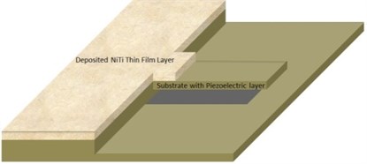
We chose a silicon nitride (Si3N4) as the substrate material due to the following reasons: i) it can be relatively easily fabricated with a very small thickness; ii) it works as a barrier to the surface diffusion of sputtered NiTi film; and iii) it has the uniform temperature distribution. Importantly, despite the fact that the theoretical model and results presented in this paper have been primarily developed and obtained for cantilever configuration of Si3N4 nanoresonator (see Fig. 1), they are also applicable to any other substrate materials. Furthermore, for other nanoresonator configurations only the boundary conditions have to be modified.
Fig. 1Silicon nitride cantilever nanoresonator with NiTi thin film
NiTi thin films are usually prepared by the magnetron sputtering method with a film thickness greater than 100 nm [16]. In this case the NiTi film density is approximately 6450 kg/m3 and its Young’s modulus can be considered to vary from 25 to 80 GPa depending on the temperature [16, 17]. Density of silicon nitride is about 3200 kg/m3 and its Young’s modulus is 310 GPa. It is important to note that the temperature dependence of Young’s modulus of NiTi film accompanied by the corresponding change of the interlayer stress in film and substrate exhibits hysteresis and, consequently, it matters whether the current temperature was attained by cooling or heating [16] (for a detailed discussion on the stress generation in NiTi film and its dependency on temperature see Ref. [18]). This hysteresis is related to the phase transformations in NiTi and resulted changes in the generated interlayer stress and, as such, it depends on the exact NiTi film composition and preparation processes, e.g. deposition and annealing temperatures [18]. Therefore, in case of nanomechanical resonators the linear part of temperature dependency of the Young’s modulus (and/or resulting stress) can differ for heating and cooling. As a result, in model to account for the real experimental conditions, it necessary to find a dependency of NiTi film Young’s modulus and the resulting interlayer stress on temperature for both cooling and heating branches. It is worth noting that the Young’s modulus of NiTi film can be determined by either nanoindentation [19] or the recently developed resonant based method [20, 21].
Dynamic behavior of the nanoresonators with NiTi film can be accurately predicted by the classical beam theory. Following the approach given in Ref. [22], a set of governing equations of motion for dynamic deflection of the resonator can be formulated as:
where is the resonator deflection, is spatial coordinate, is time, and are the driving and hydrodynamic forces per unit length, respectively [23]; , , , , [24], , , , [25], is the temperature depending average interlayer stress in film and substrate with due account for a phase transfromation in NiTi film [18], and are the width and length of the resonator, respectively; , , are the Young’s modulus, thickness and density of substrate (subscript ) and sputtered NiTi film (subscript ), is the substrate moment of inertia and is length of partially sputtered NiTi film. In general, the resonant frequencies of cantilever beam vibrating in air or viscous fluid are given by [23]:
where is density of the surrounding fluid, is the dimensionless hydrodynamic function obtained from solution of the appropriate continuity equation and Navier-Stokes equations [26] and are the resonant frequencies of beam in a vacuum obtained by solving Eq. (1) for and the usual clamped-free end conditions:
Furthermore, to solve Eq. (1) requires imposing the following matching conditions [27]:
Now, solving Eq. (1) for the boundary and matching conditions given by Eqs. (3a) and (3b) results into the transcendental equation, which positive roots are the resonant frequencies of the cantilever nanoresonator with partially sputtered NiTi film, and this equation reads:
where:
and is the desired nanoresonator angular resonant frequencies.
3. Results and discussion
In this section, we examine the impact of thickness () and length () of sputtered NiTi film on the first three consecutive resonant frequencies of the cantilever. First of all, we recall a known fact that the added mass caused by deposited film shifts the resonant frequencies of resonator to the lower values, while an increase of film stiffness and interlayer stress due to CTE difference and phase transformation in NiTi shifts the resonant frequencies to the higher values. Hence, the resulting frequency shift is the combination of all three mentioned parameters. In addition, the value of frequency shift depends also on the considered vibrational mode through a mode shape [28].
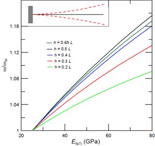
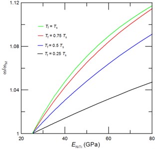
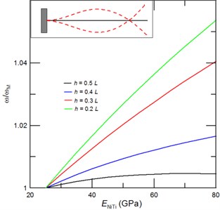
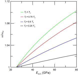
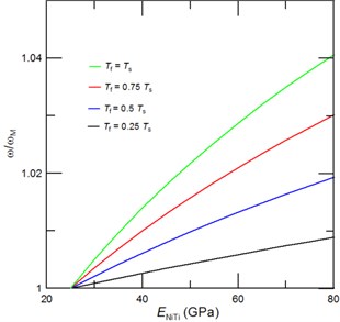
Fig. 2The achievable tuned first resonant frequencies represented through the frequency ratio ω/ωM, where ω is the cantilever resonant frequency with due account for a phase transformation of NiTi film and ωM is the resonant frequency of cantilever with NiTi film in the martensite phase, as function of the NiTi Young’s modulus for a) a given film thickness of Tf= 0.5Ts, and a given length of the deposited NiTi film of b) 0.5L, c) 0.3L and d) 0.2L. Inset of Fig. 2(a) shows the corresponding mode shape
a)
b)
c)
d)
Namely, the effect of added mass is dominant nearby the anti-node, while stiffness dominates the resonant frequencies in a vicinity of the node. For instance, for the first (fundamental) vibrational mode of cantilever, the impact of added mass on the resonant frequency is zero at the clamped end and it exponentially grows until it reaches its maximum at the cantilever’s free end (see Inset of Fig. 2(a)). Similarly, the effect of stiffness on the resonances is largest near the clamped end and is zero at the free end. Thus, for a given film thickness, there must be a critical length of the sputtered NiTi film (), at which the maximum resonant frequency tuning can be achieved. We have found that in case of NiTi film thickness 0.5 this desired maximum fundamental resonant frequency tuning of 17.8 % is realized at value of 0.55. Then, by a further increase of film thickness the added mass comes into play and the achievable resonant frequency tuning decreases as shown in Fig. 2(a). For a given sputtered NiTi film length () a critical film thickness can be estimated from Eq. (4). For a fundamental resonant frequency and , the critical film thickness of 1.3 is determined and it corresponds to the extraordinary high tunability of 33 %. Figures 2(b)-2(d) display dependency of the achievable fundamental resonant frequencies of the cantilever with NiTi film of different film thicknesses and length of 0.2, 0.3 and 0.5, respectively. Furthermore, as can be seen from Fig. 2 the increase of NiTi film thickness enables a higher fundamental frequency tuning than an increase of the deposited film length . Interestingly, even for a film of 0.5L and an exceptional frequency tuning of 29 % can be achieved.
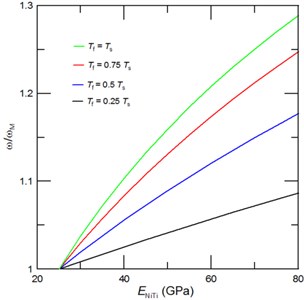
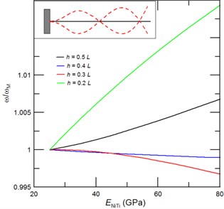
Fig. 3The achievable tuned second resonant frequencies represented through the frequency ratio ω/ωM, where ω is the cantilever resonant frequency with due account for a phase transformation of NiTi film and ωM is the resonant frequency of cantilever with NiTi film in the martensite phase, as function of the NiTi Young’s modulus for a) a given film thickness of Tf= 0.5Ts, and a given length of the deposited NiTi film of b) 0.5L, c) 0.3L and d) 0.2L. Inset of Fig. 3(a) shows the corresponding mode shape
a)
b)
c)
d)
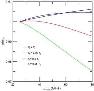
In comparison to fundamental vibrational mode the second one contains the additional node and anti-node as illustrated in Inset of Fig. 3(a) [29, 30]. Consequently, the frequency shift of second vibrational mode differs essentially from the one obtained for first mode. Since it contains an anti-node in a near vicinity of 0.5, the tunability of second resonant frequency would decrease with an increase of the film length. Indeed, results presented in Fig. 3(a) confirmed that for 0.5 the frequency tunability of second vibrational mode significantly decreases with an increase of sputtered NiTi film length. We also found that for 0.5 the critical film thickness is about 0.25(see Fig. 3(b)). Interestingly, the achievable tunabilities of the second resonant frequency for NiTi film of length 0.2, 0.3 and 0.5 are 10.5 %, 9 % and 6 %, respectively.
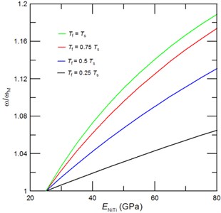
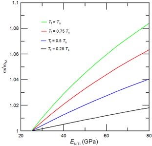
Fig. 4The achievable tuned third resonant frequencies represented through the frequency ratio ω/ωM, where ω is the cantilever resonant frequency with due account for a phase transformation of NiTi film and ωM is the resonant frequency of cantilever with NiTi film in the martensite phase, as function of the NiTi Young’s modulus for a) a given film thickness of Tf= 0.5Ts, and a given length of the deposited NiTi film of b) 0.5L, c) 0.3L and d) 0.2L. Inset of Fig. 4(a) shows the corresponding mode shape
a)
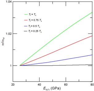
b)
c)
d)
The mode shape of third consecutive vibrational mode includes three nodes and anti-nodes (see Inset of Fig 4(a)). In Figs 4(a)-4(d) we present the estimated achievable resonant frequency tunability of third vibrational mode as a function of deposited NiTi film length and thickness. The following conclusions can be drawn from Figs. 4(a)-4(d): i) the achievable tunability of third resonant frequencies depends strongly on the deposited film length (), i.e. if anti-node is contained in a deposited film, then the tunability is strongly affected by the added mass; ii) for film which contains two anti-nodes and one node the overall tunability is dominated by a stiffness effect; and iii) desired resonant frequency tuning is highest for cantilever with NiTi film of length that do not contains any anti-node. Particularly, in present case the highest resonant frequency tuning can be obtained for film of 0.2. Then, by a further increase of NiTi film length () the anti-node is reached and the added mass due to film causes a lowering of tuned resonant frequencies as shown in Figs. 4(a) and 4(c). And, if length of deposited film is further increased beyond the anti-node, then the maximum vibrational amplitude decreases till it reaches the zero value at the node. Thus, for 0.4 we observe decrease of the resonant frequency, while for 0.5 a stiffness again dominates dynamic behavior of the nanoresonator and, consequently, a phase transformation of NiTi film shifts again the resonant frequencies to the higher values.
4. Conclusions
In this paper, we have carried out the fundamental analysis of a novel active cantilever resonant frequency tuning mechanism utilizing the significant changes in NiTi film Young’s modulus and interlayer stress during its phase transformation that is sputtered only partially on the elastic substrate materials. We have found that for NiTi film of length 0.5 and thickness 1.3 an extraordinary high fundamental resonant frequency tuning of 33 % can be achieved. The analysis shows that within the considered ranges of sputtered NiTi film thicknesses and lengths only an increase of first (fundamental) resonant frequencies can be realized. However, since higher vibrational mode contains additional nodes, the upward and downward frequency tuning is possible. These findings are particularly important in a real-time adsorbate bio- or chemical molecule determination, where the adsorbate molecule does increase mass and also creates a surface stress, i.e. molecule affects both cantilever stiffness and mass.
References
-
Stachiv I., Fedorchenko A. I., Chen Y.-L. Mass detection by means of the vibrating nanomechanical resonators. Applied Physics Letters, Vol. 100, 2012, http://dx.doi.org/10.1063/1.3691195.
-
Eom K., Park H. S., Yoon D. S., Kwon T. Nanomechanical resonators and their applications in biological / chemical detection: Nanomechanics principles. Physics Reports, Vol. 503, 2011, p. 115-164.
-
Stachiv I. On the nanoparticle or macromolecule mass detection in fluid utilizing vibrating micro-/nanoresonators including carbon nanotubes. Sensor Letters, Vol. 11, 2013, p. 1-4.
-
Stachiv I., Zapomel J., Chen Y.-L. Simultaneous determination of elastic modulus and density/thickness of ultrathin film utilizing micro-/nanoresonators under applied axial force. Journal of Applied Physics, Vol. 115, 2014, http://dx.doi.org/10.1063/1.4869415.
-
Fedochenko A. I., Stachiv I., Wang W.-C. Method of viscosity measurement by means of the vibrating micro-/nanomechanical resonators. Flow Measurement and Instrumentation, Vol. 32, 2013, p. 84-89.
-
Zhang W.-M., Hu K.-M., Peng Z.-K., Meng G. Tunable micro- and nanomechanical resonators. Sensors, Vol. 15, 2015, p. 26478-26566.
-
Jensen K., Weldon J., Garcia H., Zettl A. Nanotube radio. Nano Letters, Vol. 7, 2007, p. 3508-3511.
-
Stachiv I. Impact of surface and residual stresses and electro-/magnetostatic axial loading on the suspended nanomechanical based mass sensors: a theoretical study. Journal of Applied Physics, Vol. 115, 2014, http://dx.doi.org/10.1063/1.4880396.
-
Stachiv I., Fang T.-H., Jeng Y.-R. Mass detection in viscous fluid utilizing vibrating micro- and nano-mechanical mass sensors under applied axial tensile force. Sensors, Vol. 15, 2015, p. 19351-19368.
-
Jun S. C., Huang X. M. H., Manolidis M., Zorman C. A., Mehgegary M., Hone J. Electrothermal tuning of Al-SiC nanomechanical resonators. Nanotechnology, Vol. 17, 2006, p. 1506-1511.
-
Karabalin R. B., et al. Piezoelectric nanomechanical resonators based on aluminum nitride thin films. Applied Physics Letters, Vol. 95, 2009, http://dx.doi.org/10.1063/1.3216586.
-
Kafumbe S. M. M., Burdess J. S., Harris A. J. Frequency adjustment of microelectromechanical cantilevers using electrostatic pull down. Journal of Micromechanics and Microengineering, Vol. 15, 2005, p. 1033-1039.
-
Kozinsky I., Postma H. W. Ch., Bargatin I., Roukes M. L. Tuning nonlinearity, dynamic range, and frequency of nanomechanical resonators. Applied Physics Letters, Vol. 88, 2006, http://dx.doi.org/10.1063/1.2209211.
-
Karabalin R. B., et al. Stress-induced variation in the stiffness of micro- and nanocantilever beams. Physical Review Letters, Vol. 108, 2012, https://doi.org/10.1103/PhysRevLett.108.236101.
-
Lee K. B., Lin L., Cho Y. H. A closed – form approach for frequency tunable comb resonator with curved finger contour. Sensor and Actuators A: Physical, Vol. 141, 2008, p. 523-529.
-
Miyazaki S., Fu Y. Q., Huang W. M. Thin Film Shape Memory Alloys: Fundaments and Device Applications. Cambridge University Press, Cambridge, UK, 2009.
-
Duerig T. W., Melton K. N., Stockel D., Wayman C. M. Engineering Aspects of Shape Memory Alloys. Butterworth-Heinemann, New York, USA, 1990.
-
Fu, Y., Du H., Zhang S. Sputtering deposited TiNi films: relationship among processing, stress evaluation and phase transformation behaviors. Surface Coating Technology, Vol. 167, 2003, p. 120-128.
-
Wu S.-C, Jeng Y.-R., Yau W.-H., Wu K.-T., Tsai C.-H. Nanoindentation response of zinc titanite thin films deposited by co-sputtering process. Applied Surface Science, Vol. 258, 2012, p. 6730-6734.
-
Stachiv I., Vokoun D., Jeng Y.-R. Measurement of Young’s modulus and volumetric mass density/thickness of ultrathin films utilizing resonant based mass sensors. Applied Physics Letters, Vol. 104, 2014, http://dx.doi.org/10.1063/1.4866417.
-
Stachiv I., Kuo C.-Y., Fang T.-H., Mortet V. Simultaneous determination of the residual stress, elastic modulus, density and thickness of ultrathin film utilizing vibrating doubly clamped micro-/nanobeams. AIP Advances, Vol. 6, 2016, http://dx.doi.org/10.1063/1.4947031.
-
Fedorchenko A. I., Stachiv I., Wang A.-B. Fundamental frequencies of mechanical systems with N-piecewise constant properties. Journal of Sound and Vibrations, Vol. 317, 2008, p. 490-495.
-
Sader J. E. Frequency response of cantilever beams immersed in viscous fluids with applications to the atomic force microscopy. Journal of Applied Physics, Vol. 84, 1998, p. 64-76.
-
Zapomel J., Stachiv I., Ferfecki P. A novel method combining Monte Carlo_FEM simulations and experiments for simultaneous evaluation of the ultrathin film mass density and Young’s modulus. Mechanical Systems and Signal Processing, Vols. 66-67, 2016, p. 223-231.
-
Stachiv I., Fang T.-H., Chen T.-H. Micro-/nanosized cantilever beams and mass sensors under applied axial tensile/compressive force vibrating in vaccum and viscous fluid. AIP Advances, Vol. 5, 2015, http://dx.doi.org/10.1063/1.4936421.
-
Landau L. D., Lifschitz E. M. Fluid Mechanics. Pergamon Press, Oxford, England, 1987.
-
Naguleswaran S. Transverse vibration and stability of an Euler-Bernoulli beam with one step change in cross-section and in axial force. Journal of Sound and Vibration, Vol. 270, 2004, p. 1045-1055.
-
Ruz J. J., Tamayo J., Pini V., Kosaka P. M, Calleja M. Physics of nanomechanical spectrometry of viruses. Scientific Reports, Vol. 4, 2014, https://doi.org/10.1038/srep06051.
-
Kelly S. G. Fundamentals of Mechanical Vibrations. 2nd Edition, McGraw Hills, Singapore, 2000.
-
Bokaian A. Natural frequencies of beams under tensile axial loads. Journal of Sound and Vibration, Vol. 142, 1990, p. 481-498.
Cited by
About this article

This work was supported by the Grant Agency of Czech Republic, under GACR 15-13174J.
