Abstract
The firing stability is a hot issue in the field of gun vibration research. For the test results of the gun firing stability, in order to overcome no time information, low measuring accuracy and method obsolete of the traditional mechanical-stylus method, a multi-dimension dynamic tester has been designed by combining the sensing components of linear displacement and angular displacement with mechanical designing principle. With the self-propelled artillery firing, the tester can obtain not only the displacement-time curve of the chassis back-forth and up-down translational motion and the pitching motion but also the motion trajectory of the firing plane. The traditional mechanical-stylus test method can be replaced by electricity test method for the gun firing stability measurement. It has been proved that the tester can meet the measurement requirements through range firing test application of multiple gun firing stability.
1. Introduction
Artillery is the large complicated weapon system of firepower and defenses for world armies, and is one of widely equipped and frequently used weapons. Because of the demand of quick mobility deployment in the modern warfare, the self-propelled gun becomes the main equipment for the artillery [1]. Under the action of bore force, the pitch, yaw, roll, recoil and counter-recoil, jumping and subsidence movement will occur for the chassis of the self-propelled gun, and the firing stability problem will appear, thus the dynamic characteristics of the chassis can reflect the firing stability even more. Self-propelled gun chassis is the fire system carrier and its motion characteristics plays a key role in the muzzle vibration and firing dispersion, and especially for the self-propelled howitzer weapon system and self-propelled anti-aircraft gun system, the dynamics characteristics of the chassis is significantly important. It has been shown that, for the self-propelled howitzer weapon system, the crawler tensioning degree and driving wheel brake condition are crucial to the chassis movement and have direct influence on the firing precision. When the chassis suspension decency is unlocked, the chassis can obviously do up-down and pitch motions, and the vertical target density will not be able to meet the tactical and technical index. But when the chassis suspension decency is unlocked, the up-down and pitch motions can be decreased, and the vertical target density may be increased about 2 times. Thus, the gun firing stability is closely related to the firing precision. Experimentally obtaining the translational and pitch displacement of the chassis in the firing plane is important to examine the gun design, fault diagnosis and structural modification. Because the spatiality of movement and complexity of trajectory of the chassis restrict the application of current sensor technology in this field, the artillery weapons development urgently needs multi degree of freedom displacement measurement sensor system.
Now, the traditional mechanical-stylus method is mainly used in the firing stability test, that is, a test plane area nearly vertical is selected on the side of the chassis, and near the area a bracket fixed on the ground with a mechanical stylus. When firing, because the chassis moves relatively to the stylus, the stylus can draw a trajectory in the test area on the chassis. This track line neither has time information nor corresponds to the projectile muzzle moment or the gun part movement moment. More often, the test method is obsolete, the test data processing is inconvenient, and the error is bigger. Therefore, different test methods have been studied. In literature [2], the authors used steel wire displacement sensors to measure the back-forth and up-down displacement of the chassis. Three points which are not in a straight line were selected on the chassis with a transducer respectively, and then the chassis translation displacement on the firing plane were obtained by solving equations. However, due to the big error with wire elasticity, the complex test processing and time-consuming data processing, this method has not been popularized. In literature [3], the photoelectric detection and computer data processing technology were used in the measurement of gun firing stability. The position sensor is disposed on the ground and a light-emitting diode illuminating on the sensor was fixed on the chassis, the back-forth and up-down displacement of the chassis could be obtained. Because the motion of translation, roll and yaw of the chassis couple together, the output signal cannot be separated with no practicability. A three-dimensional displacement dynamic testing device for moving object were designed in literature [4], which mainly rely on mechanical drives. This method has not been popularized due to the big inertia of parts. In literature [5], the high-speed photography method was used to measure the displacement of the gun chassis, with video image processing technology and image matching method. Due to the dust, the muzzle smoke, and the sensitivity of the method to the ground vibration, its use is limited. In literature [6], the detection system based on wireless distributed network signing were designed for self-propelled gun chassis system, and two vibration signals of the engine cylinder cover were researched, but it does not deal with the firing stability. Presently, the widely used displacement sensor are mainly one-dimension [7]. When the measured object is in plane motion or space motion, the displacement sensor either has not accurate output data or is damaged.
In order to solve the technology problem of the gun firing stability measurement, the authors have designed a multi-dimension dynamic displacement tester. With the self-propelled artillery firing, the tester can obtain not only the displacement-time curve of the chassis back-forth and up-down translational motion and the pitching motion but also the motion trajectory of the firing plane. It has been proved that the tester can meet the measurement requirements through range firing test application of multiple gun firing stability.
2. Measuring principle
As the self-propelled artillery firing, the chassis moves mainly on the firing plane with three degrees of freedom movement as back-forth, up-down and pitch. That is to say, the chassis movement is mainly plane motion.
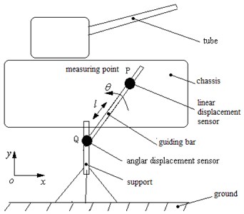
The technical scheme for the gun firing stability measuring is that, based on sensor combination technology, structure design principle and mechanism kinematics geometry relationship, the multi-dimension dynamic displacement tester and system can realize the synchronous test of three degree of freedom displacement for the chassis on the firing plane. This system is composed of the conversion subsystem of machinery amount to the electricity amount, the data acquisition module and the calculation display module, and the conversion subsystem of machinery amount to the electricity amount is composed of two displacement sensitive components, namely an angular displacement sensitive element and a linear displacement sensitive element. The angular displacement sensitive element is composed of a housing and a rotor and the linear displacement sensitive element is composed of a guiding rod and a slider. The working principle of the multi-dimension dynamic displacement tester is that a connecting device with a chute is fixed at the measured point on the chassis, and then the slider on the linear displacement sensitive element not only can slide in the chute in the connecting device but also can slide on the guiding rode on the linear displacement sensitive element. The shaft of the angular displacement sensitive element rotates by driving of the guiding rod on the linear displacement sensitive element, and the housing of the angular displacement sensitive element is fixed on the tester bracket which is fixed on the ground. As the output signal of the tester is transformed to the data acquisition system, after mechanism kinematics analysis and computer software processing, the output of the tester can reflect the plane motion of the measured point on the chassis with respect to the ground. Because the tester is connected to chassis by a spherical hinge, and a chute, it eliminates the influence of the yaw, roll and left-right translation motion of the chassis on the testing results.
Fig. 1 shows the measuring principle of the multi-dimension dynamic displacement tester, as shown, point is the measuring point, point is the angular displacement sensitive element, represents the angle output of the angular displacement sensitive element, represents the line output of the slider in the linear displacement sensitive element relative to the guiding rod.
Fig. 1The measuring principle of the multi-dimension dynamic displacement tester
In Fig. 2, the Cartesian coordinate system is established with positive as horizontal forward direction representing the back-forth displacement of the chassis, positive as vertically upward direction representing the up-down displacement of the chassis, axis indicating the left-right direction and as the origin of coordinates. The initial angle between the guiding rod of the linear displacement sensitive element and the positive is , and the initial displacement between the point and the point is , namely the initial distance between the point and the point is . As gun firing, the chassis do plane motion in plane, with the rotation angle of the angular displacement sensitive element (the angle to the positive ) and the linear displacement of the linear displacement sensitive element (i.e. the transient distance between the point and the point is ). Then in plane, the back-forth displacement and up-down displacement of the chassis can be expressed as:
As 0 indicating the forward displacement, 0 indicating the backward displacement, 0 indicating the upward displacement and 0 indicating the downward displacement.
In the firing plan, the measurement of the pitching angle of the chassis is realized as follows, simultaneously, two testers are respectively arranged at the front and back measured points on the same side of the chassis, then the pitching angle displacement-time curve can be obtained. The calculation principle was described as below.
As shown in Fig. 2 and 3, point 1 and point 2 were selected on the chassis, then the tester is connected to the chassis at the two points. At the initial position, the original point coincide with point 1, and indicating the horizontal direction, indicating the vertical direction. Initially, the coordinates of point 1 and point 2 in are 1(, ) and 2(, ) respectively. According to the two-point straight line formula, the slope of the straight line through point 1 and point 2 at the initial position in is:
Fig. 2The initial position
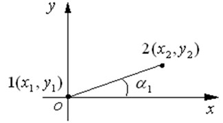
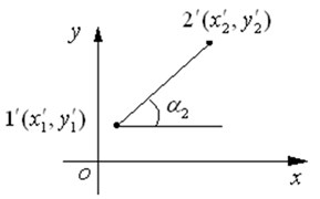
Fig. 3The transient position
The angle between the straight line 12 and axis is:
As gun firing, the chassis do plane motion and the point 1 and point 2 moves to point and point respectively. The displacements of the two points are and .
Then, the coordinates of point and point in are:
The slope of the straight line through point and point in is:
The angle between the straight line and axis is:
The rotation angle of the chassis, namely the pitch angle displacement is:
The Eqs. (1), (2) and (9) are the calculation model which is used in the calculation display module. By using computer programming technology, output of the test curve has been realized.
After error analysis and practical calibration, for the tester, the linear displacement range is 600 mm, the angular displacement range is 30°, and the measurement accuracy is 0.1 % F.S.
3. Application
By using the tester some self-propelled artillery firing stability test application has been completed.
The measured point was selected at the front of the chassis. The backward and upward displacement-time curves of the front of chassis and the trajectory of the measured point in the firing plane has been shown in Fig. 4. Positive and positive indicate the forward and upward motion of the chassis respectively. The measurement results show that, during 10 running fire, the front of the chassis does backward and upward motion simultaneously as the shot number increasing. For the tenth running fire, the backward and upward displacement reached maximum. After firing, the chassis returned. The numbers on the curve represent the fire order and the exiting moment for each projectile, with time , backward displacement , and upward displacement .
Fig. 4The measuring curve of the chassis motion of the self-propelled artillery
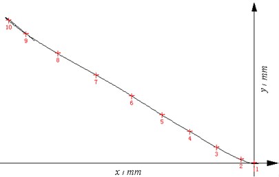
a) The trajectory curve of the measured point
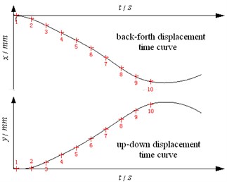
b) The front and back, up and down displacement time curves
4. Conclusions
1) The self-designed and developed multi-dimension dynamic tester can obtain not only the displacement-time curve of the chassis back-forth and up-down translational motion and the pitching motion but also the motion trajectory of the firing plane. The technology problem of the gun firing stability measurement has been solved. It has been proved that the tester can meet the measurement requirements through range firing test application of multiple gun firing stability.
2) It not only improved the measurement accuracy, but also improved the automation of the measuring process by replacing the traditional mechanical-stylus test method without time information with electricity test method including the time information for the gun firing stability measurement. The test system contains no optical sensitive element, therefore, has the function of anti-muzzle smoke and dust.
3) It can be used not only for self-propelled gun firing stability measurement, but also for the towed gun stability measurement.
References
-
Tan Lebin, Zhang Xiangyan, Guan Honggen, et al. Introduction of Gun. Beijing Institute of Technology Press, Beijing, 2005, (in Chinese).
-
Feng Changgen, Wen Bo A test method of the movement of an artillery on fire. Journal of Test and Measurement Technology, Vol. 15, Issue 2, 2001, p. 121-125, (in Chinese).
-
Zhang Fan, Yuan Feng, Xu Xiping, et al. A research on the vehicle body stability photoelectric testing system. Shanghai Measurement and Testing, Vol. 37, Issue 2, 2010, p. 6-9, (in Chinese).
-
Wang Baoyuan, Wang Shouzhong A measuring instrument for three dimensional dynamic displacement. Acta Armamentarii, Vol. 18, Issue 2, 1997, p. 156-158, (in Chinese).
-
Ou Keyin, Fu Jianping, Zhang Peilin The vibration tests based on video frequency picture technology while gun firing. Journal of Sichuan Ordnance, Vol. 29, Issue 5, 2008, p. 22-25, (in Chinese).
-
Li Wei The Study on Embedded Condition Detection and Fault Diagnosis Technology for Chassis of Self-Propelled Gun. Jiangsu University, Zhenjiang, 2009, (in Chinese).
-
Wu Sanling, Wen Bo, Yu Yongqiang Test of Gun Dynamics. National Defence Industry Press, Beijing, 2004, (in Chinese).
About this article

