Abstract
Spline-gear-shaft (SGF), which is mainly composed of gear and spline shaft, is an important transmission system of RAT (driving the generator to output power with ram air). And its dynamic characteristics affect performance of RAT greatly. In this situation, gear coupling and spline coupling, must be taken into account when analyzing dynamics characteristics of SGF. The misalignment of axis for internal and external spline is inevitable owing to mass eccentricity and unconstrained in axial direction in a high-speed operation. Consequently, the dynamic model of SGF is established considering gear coupling and spline coupling based on whole transfer matrix method (WTMM) in this paper. In addition, numerical calculation method of meshing force for spline teeth under the condition of misalignment is presented considering the distribution force on contact surface of spline teeth in this paper, based on this, the coupled transfer matrix of misaligned spline coupling is established and the dynamic characteristics of SGF is analyzed using whole transfer matrix method with Riccati (WTMMR). The test experiments of dynamic characteristics for SGF are carried out by using portable vibration monitoring analyzer in this paper, furthermore, the time-frequency characteristics of SGF are analyzed through the analysis and processing of acceleration signal. The orders of magnitude for the first four natural frequencies with WTMMR are respectively consistent with experiment results, and the relative error is in the accepted range. Therefore, the correctness of solving meshing force and WTMMR for SGF are all verified. Moreover, it also shows that WTMMR is suitable for the analysis of complex coupled systems SGF and provides a new thought for dynamic analysis of complex shafting and promotes dynamic analysis to efficient and streamlined development.
1. Introduction
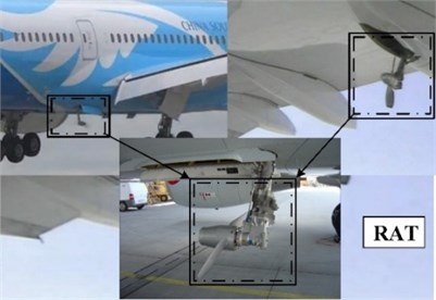
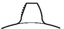
RAT which uses ram air to drive the turbine and turns generator to output power by SGF is a kind of aircraft emergency power system as Fig. 1 [1]. That, ensuring the normal running of RAT during the flight, is a prerequisite that provide electricity for aircraft used to restart the engine and ensure normal electricity supply for operating system. The dynamic characteristics of SGF (an important transmission system of power from RAT) have a critical influence on reliable operation of RAT. Therefore, the studying of dynamic characteristics for SGF is vital helpful in improving the structure and reducing noise and optimizing performance for RAT [2, 3].
At present, the research on RAT is mainly focused on two aspects: optimizing structural design and aerodynamic performance [4, 5]. Although many scholars have an extensive research for dynamics of transmission shaft, the studying on the dynamic performance of SGF is far less interesting. Dynamic model of helicopter transmission system is established on the basis of the transfer matrix method by Jianjun Wang, and the meshing transfer matrix of typical gear pair and parallel gear and planetary gear were calculated, and the torsional vibration characteristics of transmission system was analyzed on the basis of all the above [6]. In addition, Tugan Eritenel, believing that the nonlinearity of gear stiffness is caused by the contact loss of tooth surface, simulates the tooth contact loss with discrete stiffness, as well as confirming the nonlinearity of partial contact loss through experiment [7]. The dynamic model of gear with 12 freedom was established by Lassâad Walha considering the backlash and time-varying meshing stiffness, in addition, the influence of load on the dynamic characteristics of gear system is analyzed after solving the dynamic model with Newmark-iterative-algorithm [8]. It is not difficult to find that dynamic analysis of spline shaft less than gear. Instability and self-excited oscillation at critical speed of spline coupling was studied Brommundt using numerical method [9]. Furthermore, the model of spline was established by Teng Gao with finite element method, on this foundation, the influence of spline force on stability of spline system was studied using eigenvalue method [10]. Xiangzhen Xue, establishing dynamic equation of four freedom using the lumped mass model, obtained the synthetic time-varying meshing stiffness and the number of actual contact teeth for spline with four order Runge-Kutta method [11]. Yuanqiang Tan made a research about the distribution of contact-pressure of teeth under the circumstance of radial and angular misalignment using finite element method only, but not study for this by numerical method [12].
Fig. 1Ram air turbine
From the above comprehensive analysis, many scholars have done substantial research on the dynamic characteristics of gear or spline, however, the study of dynamic characteristics for shafting consisting of spline and gear is rare. In their research methods, the method of solving differential equations is adopted by most researcher, leads to huge and complex dynamic models for shafting comprising many components. Therefore, this paper establishes dynamics model for this kind of shafting by means of a new method (WTMM). This approach, contributes to simplify the complexity and reduce redundancy solving procedure, can quickly analyze the dynamic characteristics without complicated calculation process. Besides, the proposed analytical model can be also applied in dynamics analysis of other complex shaft systems. Research in this paper provides a new idea for dynamic analysis of complex shafting and promotes dynamic analysis to efficient and streamlined development.
In this paper, the dynamic model of SGF with 10 freedom is established by WTMM in consideration of more freedom and complexity of solving differential equation. The comprehensive meshing stiffness of spline is analyzed under this circumstance of misaligned spline coupling, in addition, the comprehensive meshing force of spline teeth and the coupling transfer matrix of spline shaft were established respectively. The natural frequency and shape curve of SGF were calculated with the coupling transfer matrix of bevel gear and the obtained coupling transfer matrix of spline shaft based on WTMMR. Furthermore, the influence of meshing stiffness on moving distance and natural frequency are analyzed. The experiment of dynamic performance was carried out with portable vibration monitoring analyzer to verify the correctness of analysis method for SGF proposed in this paper, vibration signal is detected by piezoelectric acceleration probe. The relative error of natural frequency obtained by experiment and WTMMR proposed in this paper is 2.5 %, thereupon then, it is verified that the method is correct for SGF.
2. Establishment of SGF model with WTMM
2.1. Dynamic model of SGF
A great deal of special coupling structures makes it more difficult to analyze the dynamic characteristics of SGF with traditional method, therefore, WTMMR is employed to analyze kinetic characteristics of SGF on this account in this paper. The complex rotor system is divided into several substructures according as its own structure and crucial parts with WTMM, afterwards, adding the virtual units (both length and quality are 0) in the appropriate position in order to have the equal number and consistent structure of all these substructures. For the sake of fitting modular analysis, the same state vector (passing from left to right as a whole) should include the section state parameters of the same number of all substructures. The number of frequency equations is only related to the number of substructures, independent of the number of supported and coupled connections.
This is a hypothesis that the inner and outer casing of supporting system is not taken into account, therefore, the simplified model of SGF consisting of five shafts (I, II, III, IV, V) is shown as Fig. 2. From this picture, shaft I and shaft II are coupled by the bevel gear pair, similarly, shaft IV and shaft V are coupled by the bevel gear pair, too. In addition, the central transmission shaft is made up of shaft II and shaft III and shaft IV with involute spline coupling. The power is introduced from the propeller at shaft I, then driving generator at shaft I after the transmission of energy through shaft II and shaft III and shaft IV.
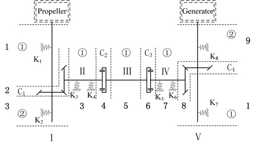
As shown in Fig. 3, SGF is divided into 2 units (1 and 2) with the model division principle of WTMM in each substructure, besides, the substructure of less than two units is filled with virtual units in order to have the equal number and consistent structure of all these substructures. Then, the partitioned units are marked into 9 segments (shaft units and coupling units) in this paper.
2.2. Calculation of whole transfer matrix for SGF
Considering the lateral and torsional vibrations of SGF, the state vector of each substructure contains ten elements (5 generalized forces and 5 generalized displacements) in this paper. The overall state vector in section can be expressed as:
In formula:
where: , , , , is the state vector of substructure (I, II, III, IV, V) in section respectively; is the component of shear force at axis; is the component of bending moment at axis; is the component of shear force at axis; is the component of bending moment at axis; is the axial torque; is the component of rotation at axis; is the component of deflection at axis; is the component of deflection at axis; is the axial torsional angle; 1, 2,…, 9; I, II,…, V.
Supposing that there is a coupling in segment (, ), the whole transfer matrix of SGF can be represented as:
The following principles need to be followed when the whole transfer matrix is constructed owing to the difference of unit’s number for each substructure and location for coupling unit while the states of each substructure are transmitted simultaneously with the overall state vector .
(1) If the state of each axis is transmitted independently in a certain period, the transfer matrix of each single axis is written to the corresponding position in the whole transfer matrix according to the method of sitting in the right seat, in addition, the coupling between the each axis is 0.
(2) If the state of an axis isn’t transmitted, the corresponding positions are represented by the unit matrix (the same order as the single axis transfer matrix) to generate the whole transfer matrix.
(3) If the coupling unit of the whole transfer matrix isn’t 0 due to the presence of coupling units between two axes, the whole transfer matrix is determined by the coordination relation of specific force balance and deformation.
Based on the above construction principle of whole transfer matrix , the whole transfer matrix of each segment can be determined as Eq. (4):
where: , , , are 5 order, 10 order, 15 order, 20 order unit matrix respectively; , , , , are respectively the transfer matrix of shaft I, shaft II, shaft III, shaft IV, shaft V at units ; and are respectively transfer matrix of shaft I and shaft V at units ; , , , are elements of coupled transfer matrix for coupling unit respectively (1, 2, 3, 4).
Supposing the solution for anisotropic support rotor systems in the form of , , , the whole transfer matrix of supporting rotor system can be expressed as Eq. (5) when the motion of the rotor in the vertical and horizontal directions are considered and the damping of the rotor system is not taken into account:
In formula:
where: ; ; ; 2/3; is the lumped weight of the rotor system; and are polar moment of inertia and radial inertia of rotation respectively; , , and are the anisotropic bracing stiffness respectively; and are spin speed and revolution speed respectively.
Fig. 2The simplified model of SGF
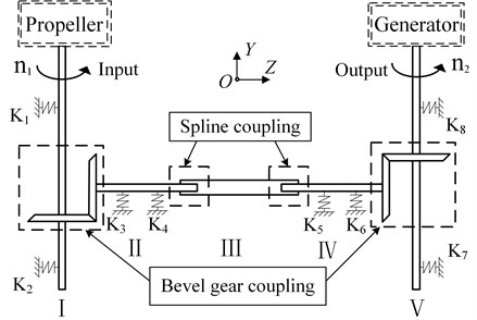
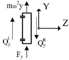
The whole transfer matrix of unsupported shaft can be obtained by making the anisotropic bracing stiffness (, , and ) being 0 in Eq. (5). As shown in Fig. 2, the state is transmitted by the coupling unit ( and ) of orthogonal bevel gear between shaft I and shaft II, shaft IV and shaft V, moreover, the shaft I and shaft IV are coupled to the shaft II and shaft V with meshing force respectively. The meshing force varies with the displacement produced by vibration generated during gear transmission. For orthogonal bevel gear, the following assumptions are made as: (1) the main part of orthogonal bevel gear is rigid, (2) the tooth of a bevel gear is flexible, (3) the meshing force is concentrated force and doesn’t change along the direction of the mesh line, (4) the acting point of meshing force is at the midpoint of contact line, (5) the meshing stiffness is stiffness in meshing direction of orthogonal bevel gear, (6) the positive direction of the line displacement and force is the positive direction of the coordinate axis, (7) the direction of angular displacement and torque is determined by the right-hand rule. For the coupling unit , the state vectors at the right end and the left end can be assumed to be Eq. (6):
where: , .
According to the relation between right state vector and left state vector of orthogonal bevel gear and , the transfer matrix of coupling unit can be obtained as Eq. (6) through literature [13]:
Fig. 3Unit division model of SGF with WTMM
3. Establishment of dynamic model for misaligned spline coupling
The spline coupling, which has many advantages (uniform force, good guidance, greater load capacity and so on), is widely used in the SGF system with high centering accuracy and great torque transmission. This state that the spline coupling hasn’t axial restraint and has certain clearance between internal and external spline causes self-excited vibration of SGF at high speeds. There is a relative displacement of axis for internal and external spline when SGF runs in high speed. Therefore, the connection performance of spline becomes worse, leading to poorer dynamic characteristics of SGF.
3.1. Calculation of meshing force
As Fig. 4, two coordinate systems are established in order to analyse expediently meshing force of misaligned spline coupling:
1. : the coordinate system of internal spline coupling;
2. : the coordinate system of the offset external spline relative to internal spline.
In Fig. 4, the dotted line is the position of the th external spline teeth when the external spline coupling isn’t offset. Points A and B A(B) is the point of addendum circle and involute for the th internal (external) spline teeth) are located on involute line of the th internal spline teeth. are the distance between point A (point B) and axis O of internal spline, namely, the addendum radius of the th internal spline teeth (external spline teeth). When the axis of internal spline and external spline aren’t offset, (the length of meshing line for the th spline teeth) can be obtained by principle of involute generation:
where: is the radius of base circle of internal spline.
Fig. 4Meshing model of misaligned involute spline coupling
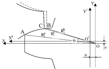
It is assumed that the axis of external spline moves distance in the positive direction of axis relative to the axis of internal spline. Owing to the smaller distance and , the change of the radian for meshing involute isn’t considered caused by offsets of the axis for external spline. The actual meshing situation is shown as thick lines in Fig. 4 when the external spline rotates a certain angle. The intersection of addendum circle and involute moves from point A to point C in the th internal spline teeth, and is the distance between point C and axis O of internal spline. The length of meshing line for the th spline teeth can be obtained by principle of involute generation:
where: (, , the rest as so on), , is spline position angle between the forward direction of axis and the radius of addendum circle for the th external spline teeth.
In Fig. 5, the meshing arc length in the th spline teeth is subdivided into parts with equal arc length , consequently, the arc length between the th point and point A, the radius of the th point in the th spline teeth relative to the axis of inner spline, the pressure angle of the th point in the th spline teeth can be represented as:
where: , 1,…, .
Considering the basal-deformation and shearing-deformation, the deformation caused by the transmission load can be divided into the following three categories based on Weber-Eenergy-Method as Fig. 6: (1) bending deformation , shear deformation , axial compression deformation at spline tooth; (2) deformation at the round corners and deformation at basal body; (3) local contact deformation caused by contact stress. The deformation caused by contact stress in the th part is equal to the deformation caused by forces when is big enough.
Fig. 5The model of equal division for meshing arc length
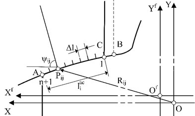
Fig. 6The deformation of spline teeth
a) Bending deformation
b) Shear deformation
c) Axial-compression deformation

d) Deformation at round corners and basal-body
e) Local contact deformation
The total deformation of the th part in the th spline teeth can be represented as:
The deformation of the internal spline teeth and external spline teeth is different under the influence of load when the spline coupling transmits torque. There’s a hypothesis that and are the comprehensive deformation of the th part for the th internal spline teeth and the th external spline teeth respectively, and is the contact deformation of the th part for the th spline teeth. Therefore, the comprehensive meshing stiffness of the th part for the th spline teeth can be expressed as:
The whole comprehensive meshing stiffness of the th spline teeth can be expressed as:
Transfer torque can be expressed with the meshing force caused by torsion:
where: , and is twist angle for each key deformation.
Therefore, the meshing force caused by torsion of the th part for the th spline teeth can be expressed in the form of Eq. (15):
The Eq. (16) is the status parameter of right side and left side for internal spline and internal :
where: , .
The internal spline and the external spline are respectively the driving shaft and the driven shaft, and the displacement of the th part for the th internal spline teeth in the meshing direction can be synthesized by the components in the direction of the axis and axis:
where: , is spline position angle of the th external spline teeth, is the included angle between and the midline of the th external spline teeth, is the pressure angle of the th part for the th internal spline teeth, is the unfolding angle of .
The meshing force caused by vibration displacement of the th part for the th spline teeth can be expressed in the form of Eq. (18):
Consequently, the comprehensive meshing force of the th part for the th spline teeth can be calculated as:
The meshing force at axis and the meshing force at axis can be calculated by the comprehensive meshing stiffness and in the direction of meshing and the angle of meshing force (the angle between normal at the th part for the th spline teeth and the positive direction of axis):
3.2. Establishment of coupled transfer matrix
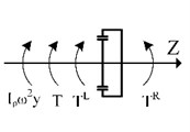
There is a hypothesis that the form of solution for status parameter can be represented as: , , . The centrifugal force of weight for spline coupling will appear as a result of vortex motion when the spline coupling runs at high speed. The moment of inertia for spline coupling can be obtained by the relative centroid theorem. The force analysis of the spline coupling is shown in Fig. 7, and the kinematics equation of internal spline can be established according to the D’Alembert principle:
where: is the weight of internal spline (drive shaft), and are diameter moment of inertia and polar moment of inertia respectively, is the spin velocity of spline coupling.
Fig. 7Equilibrium analysis of force and moment for spline coupling
a)
b)
c)
d)
e)
Similarly, the kinematics equation of external spline can be established as Eq. (22):
where: is the weight of internal spline (drive shaft), and are diameter moment of inertia and polar moment of inertia respectively.
The displacement equation of left and right sides for spline coupling agrees with the Eq. (23) according to the continuity condition of displacement:
According to the relationship about the state vectors of left and right sides, the coupled transfer matrix of spline coupling can be represented as:
where: 0:
4. Dynamic characteristic analysis of SGF with simulation and experiment
Owing to certain elements relating to in transfer matrix, the calculation accuracy will be reduced with the increase of computing frequency when the dynamic characteristics of large complex shafting is analyzed with the traditional Prohl transfer matrix method. Therefore, the WTMMR [14] is adopted to analyze the dynamic characteristics of SGF in this paper. 10 elements of the state vectors of the th part for substructure (I, II, III, IV, V) are divided into two groups, hence, the partitioned state vector of the th part can be expressed as:
where: I, II, III, IV, V.
The whole state vector in the th part can be expressed as:
Therefore, the relation of state vector for adjacent parts can be represented as:
So, the recurrence formula of WTMMR can be obtained:
Remainder of the recurrence formula is transformed for the sake of avoiding extraneous and lost roots with WTMMR, afterwards, the residue function of SGF with WTMMR can be calculated:
The natural frequency and modal shape of SGF can be obtained with Dichotomy and Gauss-elimination under the given accuracy of error. In this paper, the speeds of shafts in SGF are equal and the modulus of elasticity 2.06e11 Pa, besides, the parameters of spline coupling and bevel gear for SGF are shown in Table 1.
Table 1The parameters of spline shaft and bevel gear
Spline coupling | Bevel gear | |||
External spline | Internal spline | Modulus at main aspects | 1.5 | |
Length of shaft | 30 mm | 25 mm | Number of teeth | 35 |
Number of teeth | 20 | 20 | Pressure angle | 20 |
Modulus | 1.5 | 1.5 | Cone-apex angle | 45 |
Pressure angle | 20 | 20 | Helical angle | 12.5 |
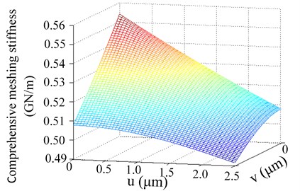
There is a hypothesis that the maximum moving distance of and are set as 2.5 μm and spline position angle 0 are analyzed. When the involute of spline tooth is divided into 800 equal parts, the varying curve of comprehensive meshing stiffness with change of moving distance is shown in Fig. 8. From Fig. 8, the comprehensive meshing stiffness of spline is largest when and are 0, furthermore, the comprehensive meshing stiffness of spline is least when and are 0.5mm. As illustrated in Fig. 8, the comprehensive meshing stiffness decreases continuously with the increase of offset distance and , besides, the effects of offset distance of and on comprehensive meshing stiffness are symmetrical. As mentioned above, the performance of connection decreases gradually with the increase of offset distance, therefore, the relative offset of the internal and external spline couplings should be minimized in order to ensure high-performance connection.
Fig. 8The varying curve of comprehensive meshing stiffness with change of moving distance
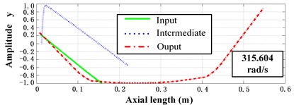
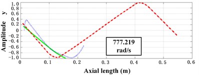
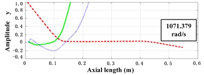
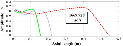
Without loss of generality, the moving distance in the positive direction of the axis and the moving distance v in the positive direction of the axis are 1.0 μm and 2.0 μm respectively, therefore, the comprehensive meshing stiffness of spline (0) is 0.513G N/m calculated by chapter 3.2. The first four natural frequency of SGF calculated using WTMMR presented in this paper are respectively: 315.604 rad/s, 777.219 rad/s, 1071.379 rad/s, 1669.928 rad/s. The relative deformation of each part can be obtained with Gauss-elimination and the recurrence formula of WTMMR on the basis of calculated natural frequencies. The SGF can be divided into input shaft (I) and intermediate shaft (II, III, IV) and output shaft (V), and the radial modal shape of the first four natural frequency for input shaft and intermediate shaft and output shaft are shown in Fig. 9. The radial modal shape of the first four natural frequency for input shaft and output shaft are basically identical due to similar structures from the Fig. 9, in addition, the radial modal shape of the first two natural frequency is smaller than the radial modal shape of latter two natural frequency.
Fig. 9The curve of radial modal shape for the first four natural frequency
a)
b)
c)
d)
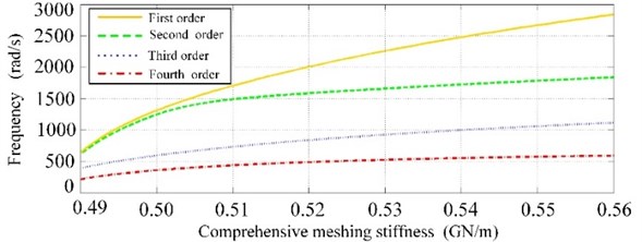
The eccentricity of spline axis has a great influence on the comprehensive meshing stiffness, and then leading to the change of natural frequency for SGF. Without loss of generality, the changes situation of the first four natural frequency where spline position angle 0 are analyzed. From Fig. 10, The influence of the change of comprehensive meshing stiffness on the first to the fourth order natural frequency is getting smaller and smaller, besides, the first four natural frequency of SGF keep going up with the increase of comprehensive meshing stiffness. This demonstrates a phenomenon that the increase of comprehensive meshing stiffness of spline is helpful to improve the stability of SGF. When comprehensive meshing stiffness is greater than 0.53 GN/m, the growth trend of the last three order is obviously slow, although the first natural frequency keep going up with the increase of comprehensive meshing stiffness but its change rate is s slowing down slowly. After the comprehensive meshing stiffness is less than 0.55, the change of comprehensive meshing stiffness has little influence on the first four natural frequency, and this illustrates that the spline meshing position tends to rigid connection.
Fig. 10The varying curve of the first four natural frequency with change of comprehensive meshing stiffness
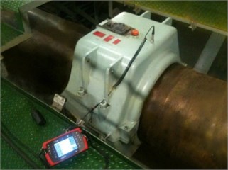
In order to verify the correctness of WTMMR in analyzing the dynamics characteristics for SGF, the experiment of dynamic performance analysis for SGF is carried out in this paper. In the experiment, piezoelectric acceleration probe is selected to collect vibration signal, and the dynamic performance test of SGF was carried out by portable vibration monitoring analyzer as Fig. 11. According to sampling theorem , the sampling frequency is 1000 Hz in order to ensure the reliability of the experimental data. The vibration voltage signal (0, 1, 2,..., ), where is the number of samples ) collected by piezoelectric acceleration probe is converted into acceleration signal with unit conversion, then the time characteristic curve in Fig. 12 can be obtained through noise signals were separated by IIR digital filter. In order to obtain displacement signals, the acceleration signal needs to be integrated through twice trapezoidal integral formula . On this basis, frequency characteristic curve can be obtained after Discrete Fourier Transform (DFT) , and the first four natural frequencies of SGF are peaks in Fig.12 respectively.
Fig. 11Frame drawing of dynamic characteristic testing for SGF
The first four natural frequencies with WTMMR and experiment and their relative error are listed in the Table 2. As shown in Table 2, the first four natural frequencies with WTMMR and experiment are respectively consistent, and the relative error which is approximately 2.5 % is within allowable error. Therefore, the correctness of solving meshing force and WTMMR for SGF are all verified, furthermore, it also shows that WTMMR is applied to the analysis of complex coupled systems SGF.
Fig. 12The time-frequency characteristic curve of SGF
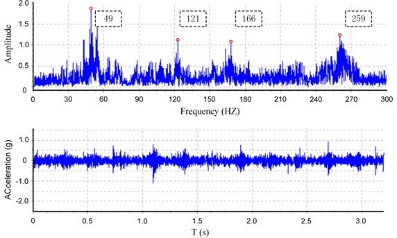
Table 2The first four natural frequencies of SGF
Order | WTMMR | Experiment | Relative error (%) |
Natural frequencies (rad/s) | Natural frequencies (rad/s) | ||
First | 315.604 | 307.876 | 2.51 |
Second | 777.219 | 760.265 | 2.23 |
Third | 1071.379 | 1043.009 | 2.72 |
Fourth | 1669.928 | 1627.345 | 2.55 |
5. Conclusions
Considering the distribution force on contact surface of spline teeth, numerical calculation method of meshing force is presented under the condition of misalignment in this paper. The coupled transfer matrix of misaligned spline coupling is established with WTMM, besides, the dynamic model of SGF is established considering gear coupling and misaligned spline coupling with WTMM. This paper gives a detailed analysis about the variation trend of the first four natural frequency with change of comprehensive meshing stiffness, and the dynamic characteristics of SGF is analyzed using WTMMR. Moreover, the test experiments of dynamic characteristics for SGF are carried out by portable vibration monitoring analyzer. By comparing outcomes of experiments, the relative error between analysis results and experimental results which is approximately 2.5 % is within allowable error. Therefore, the correctness of solving meshing force and WTMMR for SGF are all verified, and a new approach is opened up for dynamic analysis of complex shafting.
References
-
Renganathan A., Denney R. K., Duquerrois A., Mavris D. N. Validation and assesment of lower order aerodynamics based design of ram air turbines. 12th International Energy Conversion Engineering Conference, Cleveland, 2014.
-
Siyu C., Jinyuan T., Caiwang L., Qibo W. Nonlinear dynamic characteristics of geared rotor bearing systems with dynamic backlash and friction. Mechanism and Machine Theory, Vol. 46, 2011, p. 466-478.
-
Xiangzhen X., Sanxin W., Jian H., Hui W. Investigation of load distribution among teeth of an aero-engine spline coupling. Proceedings of the 5th International Conference on Electrical Engineering and Automatic Control, 2016, p. 1155-1162.
-
Walter M., Mavris D. Sequential robust design of a ram air turbine. 17th AIAA/ISSMO Multidisciplinary Analysis and Optimization Conference, Washington, 2015.
-
Jian W., Yueliang L., Fei Y. The Airfoil Aerodynamic Characteristic Analysis of Two Ram Air Turbines. Chinese Society of Aeronautics and Astronautics, China, Shenyang, 2014, p. 191-195.
-
Jianjun W., Zhenzhong M., Liwei Q., Qihan L. Torsional vibration analysis of helicopter power transmission system by the multi-shaft transfer matrix method. Journal of Aerospace Power, Vol. 10, 2008, p. 1805-1812.
-
Tugan E., Parker R. G. Three-dimensional nonlinear vibration of gear pairs. Journal of Sound and Vibration, Vol. 331, 2012, p. 3628-3648.
-
Lassâad W., Tahar F., Mohamed H. Nonlinear dynamics of a two-stage gear system with mesh stiffness fluctuation, bearing flexibility and backlash. Mechanism and Machine Theory, Vol. 44, 2009, p. 1058-1069.
-
Brommundt E., Krämer E. Instability and self- excitation caused by a gear coupling in a simple rotor system. Forschung im Ingenieurwesen, Vol. 70, Issue 1, 2005, p. 25-37.
-
Teng G., Jianping J., Qing M. Stability analysis of spline connected rotor system. Noise and Vibration Control, Vol. 2, 2016, p. 40-45.
-
Xiangzhen X., Sanmin W., Ru Y. Nonlinear dynamic characteristics of involute spline couplings. Journal of Harbin Institute of Technology, Vol. 1, 2015, p. 107-111.
-
Yuanqiang T., Jianfa H., Shengqiang J. Research of misaligned load distribution of involute spline pair based on finite element method. Journal of Mechanical Transmission, Vol. 9, 2016, p. 110-113.
-
Huiqun Y. Matrix Analysis Method for Complex Rotor System. Shenyang, 2014, p. 42-43.
-
Gangli C., Xiaoting R., Fufeng Y., Jiangshu Z. Study on the natural vibration characteristics of flexible missile with thrust by using Riccati transfer matrix method. Journal of Applied Mechanics, Vol. 83, Issue 3, 2015, p. 31006.
-
Zhifeng C. A hihgly stable and accuarte computational method for eigensolution in structural dynamics. Computer Methods in Applied Mechanics and Engineering, Vol. 195, Issue 2006, 2005, p. 4050-4059.
-
Ji W., Xiao H. Application of MATLAB in Vibration Signal Processing. China Water and Power Press, Intellectual Property Press, 2006.
Cited by
About this article

This work was supported by The National Natural Science Foundation of China (No. 51675393 and No. 51375197), the Fundamental Research Funds for the Central Universities (No. 2016YS032).
Xiangang Su established dynamic model for SGF and calculated whole transfer matrix with WTMM. Hong Lu established coupled transfer matrix for misaligned spline coupling. Xinbao Zhang calculated meshing force for misaligned spline coupling. Wei Fan constructed experiment platform and done experiments for SGF. Yongquan Zhang constructed experiment platform.
