Abstract
In order to attenuate low-frequency vibration, a novel nonlinear vibration isolator with high-static-low-dynamic stiffness (HSLDS) is developed in this paper by combining the negative stiffness corrector in parallel with a vertical linear spring. The force and stiffness characteristics are first derived by the static analysis. Then, the displacement transmissibility of the HSLDS system is obtained to evaluate the isolation performance using the harmonic balance method. The parametric analysis shows that the proposed HSLDS system can outperform the equivalent linear one in some aspects. Besides, the initial isolation frequency is defined and further investigated with the purpose of providing some useful guidelines for choosing parameter combinations conveniently. Finally, a prototype is developed and the experimental test is conducted to verify the isolation performance of the proposed HSLDS system.
1. Introduction
Recently, the nonlinear vibration isolators with high-static-low-dynamic stiffness (HSLDS) characteristic have attracted the attention of many scholars for their potential advantages in many practical applications. This kind of vibration isolator can overcome the inherent contradiction between the natural frequency and the static deflection, which exists in linear vibration isolator [1]. The HSLDS vibration isolators usually consist of an elastic element with positive stiffness and a negative stiffness corrector which is used for providing the negative stiffness to counteract the positive one. Therefore, the HSLDS vibration isolator can achieve a very low dynamic stiffness at the static equilibrium position with static stiffness unaffected. With structural parameters properly designed, the nonlinear vibration isolator can even obtain a zero stiffness at the static equilibrium position, and thus the quasi-zero stiffness (QZS) characteristic can be achieved. As a result, this kind of vibration isolator can achieve a low natural frequency with small static deflection and outperform the linear counterpart.
Alabuzhev et al. [2] proposed a variety of prototypes of the QZS vibration isolator and made a classification. Platus [3] proposed a unique vibration isolator by using two axially loaded beams to achieve the negative stiffness for horizontal vibration isolation. Carrella et al. [4, 5] developed an HSLDS vibration isolator that consists of a vertical spring and two oblique springs, and demonstrated its excellent vibration isolation performance. Robertson et al. [6] built a QZS vibration isolator composed of two magnetic springs and gave the design criteria. Zhou and Liu [7] developed an HSLDS vibration isolator that consists of a beam and a pair of electromagnets, and demonstrated good isolation performance by experimental study. Le and Ahn [8, 9] studied the isolation performance of an HSLDS vibration isolator comprehensively using two symmetric structures as negative stiffness corrector for a vehicle seat. Zhu et al. [10] investigated the isolation performance of a magnetic suspension vibration isolator using rubber ligaments to obtain the negative stiffness. Liu and Huang et al.[11, 12] then built a QZS vibration isolator using Euler buckled beams as negative stiffness corrector and investigated the dynamic behavior and isolation performance theoretically and experimentally. Shaw et al. [13] developed an HSLDS vibration isolator using a bistable composite plate as negative stiffness corrector. The experiment results demonstrated that it possesses wider isolation frequency band and lower peak response. Zhou and Cheng et al. [14, 15] investigated the dynamic behavior and isolation performance of a QZS vibration isolator using the cam-roller-spring mechanisms as negative stiffness corrector.
Recently, Meng et al. [16] built a QZS vibration isolator using a disk spring as negative stiffness corrector for micro-vibration isolation and analyzed the dynamic behavior theoretically. Sun and Jin [17] developed a nonlinear vibration isolator mainly constructed by an n-layer scissor-like structure, and found that it possesses better QZS characteristic and excellent performance. Wang et al. [18] investigated the shock isolation performance of an HSLDS vibration isolator using an analytical method, and found that HSLDS vibration isolator has better shock isolation performance than the equivalent linear one when the shock amplitude is small. More information about the nonlinear vibration isolator is given by Ref. [19].
In addition to the vibration isolator, scholars also introduced the negative stiffness into the vibration absorbers [20-24]. Acar and Yilmaz [21] proposed an adaptive–passive dynamic vibration absorber with a negative stiffness mechanism, and found that the proposed system can dramatically reduce the vibration level of the protected equipment over the range of operation frequencies. Yao et al. [22] proposed a vibration absorber combining negative stiffness with positive stiffness together to suppress the vibration of a rotor system. The results indicated that the negative stiffness can broaden the effective isolation frequency band of the absorber. Shen et al. [23, 24] further studied the optimal parameters of a dynamic vibration absorber with negative stiffness, providing a theoretical basis for optimum parameters design.
Generally, most of the negative stiffness correctors mentioned above [4, 8, 14] can achieve the negative stiffness only when the springs are compressed. As a result, mechanical instability of these correctors may occur due to the spring bending. To avoid the spring bending, guide bars are always installed [25], which makes the structure of the negative stiffness corrector complicated. Therefore, a novel HSLDS vibration isolator is proposed in this paper. Its negative stiffness corrector mainly consists of a scissor-like structure and horizontal springs, which can achieve the negative stiffness only when horizontal springs are stretched. Thus, mechanical instability induced by spring bending can be avoided.
The rest of this paper is organized as follows. In Section 2, the static characteristics of the proposed vibration isolator are analyzed in detail. In Section 3, the displacement transmissibility is obtained to evaluate the isolation performance of the HSLDS vibration isolator. In Section 4, the initial isolation frequency is defined with the purpose of providing some useful guidelines for choosing parameter combinations conveniently. The experimental test is conducted to verify the isolation performance of the proposed HSLDS system in Section 5. Conclusions are drawn in Section 6.
2. Modeling of an HSLDS vibration isolator
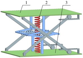
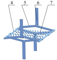
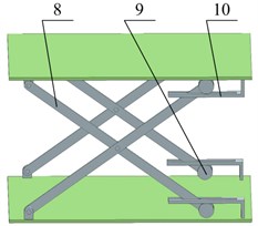
The physical model of the proposed HSLDS vibration isolator is shown in Fig. 1. The negative stiffness corrector is mainly comprised of horizontal springs, hinge axes, connecting rods and brackets. Both ends of each connecting rod are hinged with the bracket and the hinge axis, respectively. All of the connecting rods are of the same length . Besides, both ends of the horizontal spring are connected with hinge axis. The loading support can only move in the vertical direction due to the existence of the guide mechanism. When the loading support carries a load , the vibration isolator is initially balanced in the static equilibrium position where all of the connecting rods are located on the same horizontal plane. Thus, the load is only supported by the vertical spring with static deflection , where and denote the gravity of load and the vertical spring stiffness, respectively. Meanwhile, to achieve the negative stiffness, the horizontal spring is stretched at the static equilibrium position with pre-stretch length and stiffness . When the load oscillates about the static equilibrium position, the connecting rods will deviate from the horizontal plane. As a result, the stretching force can be transmitted to the loading support through the connecting rods, and its direction is opposite to that of the restoring force generated by vertical spring. Thus, the dynamic stiffness of the vibrating system is reduced with static stiffness unaffected. With structural parameters properly designed, the HSLDS characteristic can be achieved.
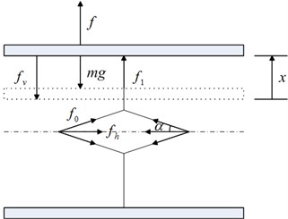
To understand more about the negative stiffness corrector, the force and stiffness characteristics are analyzed subsequently. With the payload, the schematic diagram of the static analysis at equilibrium position is shown in Fig. 2(a). When the vibration isolator is subjected to a force , the loading support deviates from the static equilibrium position by a displacement , as shown in Fig. 2(b). Note that the magnitude of the restoring force of the system equals to the applied force, but in opposite direction.
Fig. 1Physical model of the HSLDS vibration isolator with scissor-like structure: a) HSLDS vibration isolator, b) negative stiffness corrector, c) guide mechanism. 1 – loading support, 2 – vertical spring, 3 – base plate, 4 – hinge axis, 5 – connecting rod, 6 – bracket, 7 – horizontal spring, 8 – guide rod, 9 – roller, 10 – limiting groove
a)
b)
c)
Fig. 2Schematic diagram of the static analysis of the scissor-like structure and the loading support: a) static equilibrium position, b) deviation from the static equilibrium position by a displacement x

a)
b)
When the loading support deviates from the static equilibrium position by a displacement , the relationship between the applied force and the displacement is given by:
where is the vertical spring force, denotes the force generated by the negative stiffness corrector, and where is the horizontal spring force, is the angle between the connecting rod and the horizontal plane, and . Note that , thus the applied force can be further written as:
Eq. (2) can be written in a non-dimensional form for simplicity:
where , , , .
The non-dimensional stiffness of the system can be obtained by differentiating Eq. (3) with respect to the non-dimensional displacement:
The stiffness at static equilibrium position can be derived by substituting into Eq. (4):
If the stiffness of the HSLDS vibration isolator at static equilibrium position is zero, the QZS characteristic can be obtained. The QZS condition is given by:
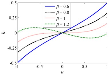
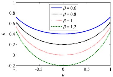
The non-dimensional force-displacement and stiffness–displacement curves for various when are shown in Fig. 3. It can be observed that the minimum stiffness corresponds to the static equilibrium position. The magnitude of the stiffness is getting smaller with the increase of . When is not greater than 1, the minimum stiffness is positive. As increases to 1, the minimum stiffness becomes zero, and thus the QZS characteristic is achieved. If increases further, such as , the negative stiffness occurs in the vicinity of the static equilibrium position, which is undesirable in engineering practice. In order to avoid an unstable system, the stiffness ratio should not be greater than . The case of is mainly considered in this work.
Fig. 3Non-dimensional a) force-displacement and b) stiffness-displacement curves for various β when δ= 1
a)
b)
With the purpose of simplifying the subsequent dynamic analysis, Eq. (3) can be further expanded as a third-order Taylor series about when the oscillation amplitude is relatively small:
where and .
Then the approximate stiffness of the HSLDS system is given by:
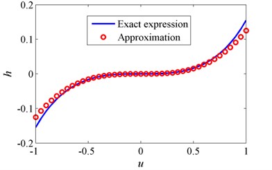
The non-dimensional exact force-displacement curve obtained by Eq. (3) and its approximate one obtained by Eq. (7) are shown in Fig. 4. It can be observed that the approximation accuracy depends on the non-dimensional displacement and becomes worse with the increase of displacement. However, the approximate curve matches well with the exact one in most of the selected displacement range, demonstrating that it is reasonable to use the approximate restoring force for subsequent dynamic analysis.
Fig. 4Comparison of the exact and approximate force-displacement curves for δ=1 and β=1
3. Displacement transmissibility
The absolute displacement transmissibility [5], which is defined as the ratio between the absolute displacement amplitude of the load and the base excitation amplitude, is used to evaluate the isolation performance of the HSLDS vibration system. A harmonic base excitation is applied to the base plate, where and denote the excitation amplitude and the frequency, respectively. Considering the linear viscous damping, the equation of relative motion of the load is governed by:
where is the relative displacement between the load and the base plate, and is the restoring force defined by Eq. (2). Writing Eq. (9) in a non-dimensional form yields:
where:
and where the dots denote derivatives with respect to . Replacing the exact restoring force with its approximate one defined by Eq. (7). Thus, the dynamic equation can be approximately given by:
In order to obtain the steady-state solution, the harmonic balance method (HBM) [5] is employed here. The first-order approximate solution is assumed to be the following form:
where and denote the amplitude and the phase of response, respectively. Substituting Eq. (11) into Eq. (10) and equating the coefficients of the terms containing and separately to zero can lead to the following equations:
Therefore, the amplitude-frequency equation can be obtained with the application of :
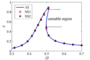
To verify the feasibility of the approximation of restoring force and the HBM, a numerical method based on the fourth-order Runge-Kutta scheme is applied. Then the fast Fourier transformation (FFT) is utilized to obtain the basic harmonic component of the response. The amplitude-frequency curves obtained by two methods are shown in Fig. 5. It can be observed that there is a good agreement between the analytical solutions and the numerical ones of Eq. (10) and Eq. (11), demonstrating that the approximation of restoring force and the HBM are feasible. Note that the numerical method can only simulate stable solutions [15]. As a result, the steady-state solutions located at the unstable region cannot be obtained by the numerical method.
Fig. 5Amplitude-frequency curves obtained by HBM and numerical method. AS denotes analytical solutions obtained by HBM, and NS1 and NS2 denote numerical solutions of Eq. (11) and Eq. (10), respectively, when δ=1, β=0.8, ζ=0.02 and z0=0.07
The absolute displacement of the load is given by:
Then the amplitude of the absolute displacement can be expressed as:
where is given by Eq. (13a). Therefore, the absolute displacement transmissibility can be written in the form of decibel:
where represents the relative displacement transmissibility. Moreover, the absolute displacement transmissibility of the equivalent linear vibration isolator (no negative stiffness corrector) is given by:
The effect of excitation amplitude on the absolute displacement transmissibility is shown in Fig. 6. It can be observed that the peak transmissibility and the resonant frequency of the HSLDS system increase accordingly when the excitation amplitude gets larger. When increases to 0.1, the curve bends to the right and the jump phenomenon occurs [26]. If increases further to 0.16, the transmissibility becomes unbounded [5, 11] and no peak can be observed. Thus, the isolation performance is inferior to that of the equivalent linear system. Note that increasing the excitation amplitude has little effect on the isolation performance in higher frequencies. It can be concluded that the HSLDS system can outperform the equivalent linear counterpart for the advantages of wider isolation frequency band and lower peak transmissibility when the excitation amplitude is not too large.
Fig. 6Absolute displacement transmissibility for various excitation amplitudes when δ=1, β=0.8 and ζ=0.02
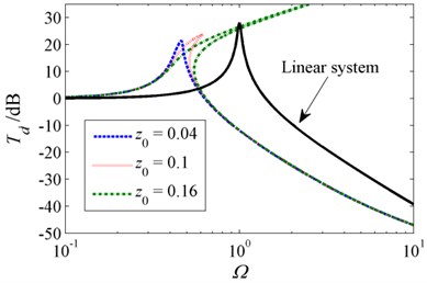
Fig. 7Absolute displacement transmissibility for various damping ratios when δ=1, β=0.8 and z0=0.1
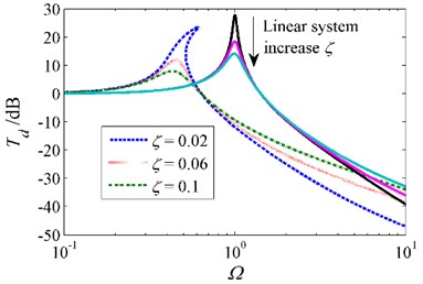
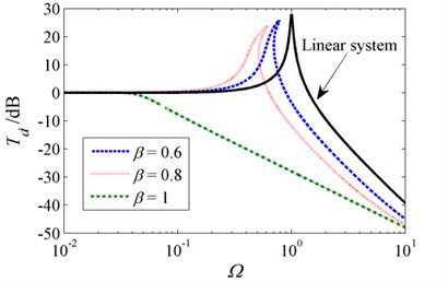
Fig. 8Absolute displacement transmissibility for various stiffness ratios when δ=1, ζ=0.02 and z0=0.1
The effect of damping ratio on the absolute displacement transmissibility is shown in Fig. 7. It can be observed that increasing the damping ratio can suppress the transmissibility in the resonant region, which is similar to the damping effect on the equivalent linear system. It can also reduce the resonant frequency and broaden the isolation frequency band in a certain extent. However, the isolation performance in higher frequencies becomes worse with the increase of damping ratio. Generally, an appropriate choice of damping ratio is beneficial to the HSLDS system, such as suppressing the transmissibility in the resonant region and improving the system stability.
The influence of stiffness ratio on the absolute displacement transmissibility of the HSLDS system is shown in Fig. 8. It can be observed that increasing the stiffness ratio can lead to the reduction of peak transmissibility and resonant frequency, broadening the isolation frequency band. When the stiffness ratio increases to 1, no obvious peak transmissibility can be observed and the whole-frequency vibration isolation is achieved. Generally, it can be concluded that choosing a greater stiffness ratio can achieve a better isolation performance.
4. Initial isolation frequency
The initial isolation frequency is defined as a critical frequency where the vibration starts to be attenuated. This is one of the major factors that should be considered in the design process of vibration isolator. Generally, the initial isolation frequency should be lower than the frequency at which the isolation is required in engineering practice. For simplicity, the frequency where the transmissibility equals to 0 dB is denoted by . According to the linear vibration theory, the linear vibration isolator comes into play at [1], which indicates that the initial isolation frequency equals to . However, the situation is different for the HSLDS system. When the jump phenomenon occurs, the jump-down frequency may be greater than , then the initial isolation frequency is determined by .
Setting in Eq. (17) to zero yields the following equation:
Combining Eq. (13a) and Eq. (19) can obtain the relationship between and the amplitude :
Then a quadratic equation about can be obtained by combining Eq. (14) and Eq. (20):
Solving Eq. (21) analytically yields:
In order to obtain the jump-down frequency [27], differentiating both sides of Eq. (14) with respect to A and setting yield:
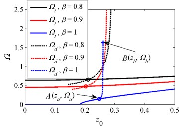
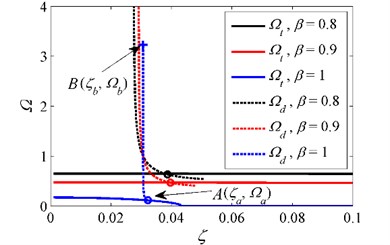
Then the jump-down frequency can be determined numerically by combining Eq. (14) and Eq. (23). The effect of excitation amplitude on the initial isolation frequency for various is shown in Fig. 8. It can be observed that increasing can reduce the value of . For the system with , the value of and keeps increasing as gets larger. Note that the jump-down frequency only exists in certain frequency range. If the excitation amplitude is not greater than , the initial isolation frequency is determined by . As the excitation amplitude exceeds , the jump phenomenon happens and the initial isolation frequency is determined by . However, if increases further and exceeds , the unbounded response occurs, and thus the initial isolation frequency no longer exists, which means that the HSLDS system loses its capacity of isolating the vibration. Therefore, the parameter combinations located in this range should be excluded in engineering practice. The situation is different for the case of . As is not greater than 0.185, the initial isolation frequency is zero, and thus the whole-frequency vibration isolation is achieved. Therefore, choosing a relatively large stiffness ratio is beneficial for the vibration isolation.
Fig. 9Initial isolation frequency for various stiffness ratios when δ=1 and ζ=0.04. ‘–’ curve of Ωt, ‘--’ curve of jump-down frequency Ωd, ‘o’ intersection between Ωt and jump-down frequency, ‘+’ critical point where the unbounded response occurs
The influence of damping ratio on the initial isolation frequency for various is shown in Fig. 9. Generally, increasing the damping ratio can reduce the value of and . For the system with , when the damping ratio is less than , the initial isolation frequency cannot be found due to the existence of unbounded response, and thus the HSLDS system fails to attenuate the vibration. As the damping ratio is greater than , the unbounded response disappears but the jump phenomenon still exists, which means that the initial isolation frequency is determined by . If increases further and exceeds , is not greater than , and thus the initial isolation frequency equals to . For the case of , if is greater than 0.043, the initial isolation frequency becomes zero, indicating that the whole-frequency vibration isolation is achieved. Generally, choosing a greater damping ratio can avoid the jump phenomenon and reduce the initial isolation frequency.
Fig. 10Initial isolation frequency for various stiffness ratios when δ=1 and z0=0.2. ‘–’ curve of Ωt, ‘--’ curve of jump-down frequency Ωd, ‘o’ intersection between Ωt and jump-down frequency, ‘+’ critical point where the unbounded response occurs
The aforementioned analysis indicates that adjusting the excitation amplitude to a lower level or applying a greater damping can lead to a lower initial isolation frequency and avoid the unbounded response. If the parameter combinations are properly selected, the HSLDS system can even achieve whole-frequency vibration isolation.
5. Experimental investigation
The experimental bench is established to verify the vibration isolation performance of the proposed HSLDS vibration isolator. The experimental prototype is excited by the shaking table. This experimental bench consists of three parts: the excitation system, the HSLDS system and the data acquisition system, as shown in Fig. 11 and Fig. 12.
Fig. 11Schematic diagram of experimental bench
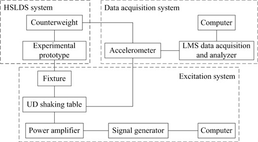
The excitation system is mainly composed of an electrodynamic shaking table, a fixture, a power amplifier, a signal generator and a computer. Specifically, the shaking table can provide a base acceleration excitation in the range of 5-3000 Hz. A power amplifier is used to amplify the excitation signal generated by a signal generator. Note that accelerometer 1 and 3 are installed on the shaking table to monitor the excitation amplitude. In order to obtain the acceleration transmissibility, the sinusoidal excitation signal is applied. The excitation frequency is increased from 5.6 Hz to 20 Hz step by step and the amplitude is 9.81 m/s2 for each frequency.
Fig. 12Experimental bench of the HSLDS vibration isolator. 1 – accelerometer 1, 2 – counterweight, 3 –accelerometer 2, 4 – accelerometer 3, 5 – UD shaking table, 6 – LMS data acquisition and analyzer, 7 –computer, 8 – fixture, 9 – accelerometer 4, 10 – scissor-like structure, 11 – vertical spring, 12 – horizontal spring, 13 – guide mechanism.
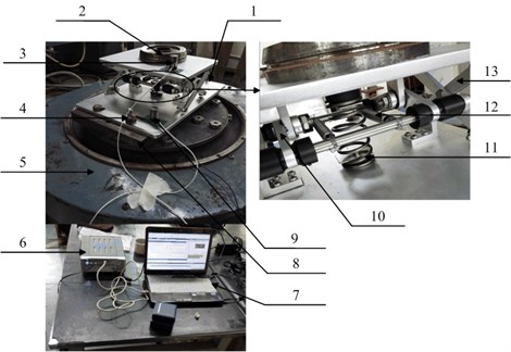
The experimental prototype is mainly made of aluminum and only two hinge axes are made of steel. The experimental prototype is fixed to the shaking table through the fixture and can only move in the vertical direction due to the existence of guide mechanism. Three kinds of horizontal springs with stiffness , and , respectively, are chosen in the test. The main parameters of the experimental prototype are listed in Table 1. Therefore, the theoretical natural frequency of the linear vibration isolator is given by 8.21 Hz. Note that the experimental prototype is in the situation of underload and the load initially deviates from the minimum stiffness point by 16 mm.
Table 1Parameters of the experimental prototype.
Parameter | Value |
4.05 kg | |
10.77 N/mm | |
1.72 N/mm | |
5.18 N/mm | |
8.31 N/mm | |
50 mm | |
20 mm |
The data acquisition system is mainly comprised of a computer, an LMS data acquisition and analyzer and two accelerometers. Accelerometer 2 is installed on the loading support to obtain the response signal and accelerometer 4 is fixed to the base plate with the purpose of obtaining the excitation signal.
FFT technique is applied to obtain the basic harmonic component of the response. Then the acceleration transmissibility is defined as the ratio between the amplitude of the basic harmonic component of the load and that of the base excitation. The experimental results are shown in Fig. 13. It can be seen that the experimental natural frequency of the equivalent linear vibration isolator is about 8.1 Hz, which is close to the theoretical one. Besides, the initial isolation frequency of the linear system is about 11.6 Hz. For the HSLDS vibration isolator with , the resonant frequency and the initial isolation frequency are about 7.6 Hz and 11.2 Hz, respectively. Thus, the resonant frequency and the initial isolation frequency are separately reduced by 0.5 Hz and 0.4 Hz compared to the linear system. For the case of , the resonant frequency and the initial isolation frequency are reduced by 1.1 Hz and 1 Hz, respectively. When the stiffness ratio increases to 0.77, the resonant frequency and the initial isolation frequency are further decreased. In addition, the peak transmissibility is lowered with the increase of the stiffness ratio.
Fig. 13Absolute acceleration transmissibility for various stiffness ratios
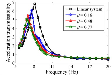
Note that the isolation performance of the HSLDS vibration isolator in the high frequency band is slightly inferior to that of the linear one. This is mainly due to the fact that a greater damping exists in the HSLDS prototype. Specifically, the frictional damping is generated by hinges. However, a greater damping is beneficial to the isolation performance in the resonant region and the stability of the HSLDS vibration isolator. Overall, it can be concluded that the HSLDS vibration isolator outperforms the equivalent linear counterpart.
6. Conclusions
In this study, a novel HSLDS vibration isolator with scissor-like structure is developed. The force and stiffness characteristics are first investigated by the static analysis. Then the absolute displacement transmissibility of the HSLDS system is obtained based on the HBM. It is demonstrated that increasing the excitation amplitude can deteriorate the isolation performance. Although increasing the damping ratio is beneficial for the suppression of transmissibility in the resonant region, the performance in higher frequencies can be deteriorated. Besides, choosing a greater stiffness ratio can obtain a wider isolation frequency band. The HSLDS vibration isolator outperforms the equivalent linear counterpart when the excitation amplitude is not too large.
The initial isolation frequency is obtained. It is indicated that adjusting the excitation amplitude to a lower level or applying a greater damping ratio can reduce the initial isolation frequency. Finally, the experiment is conducted. It is shown that the resonant frequency and the initial isolation frequency can be reduced by at least 1.1 Hz and 1 Hz, respectively, when the stiffness ratio is greater than 0.48, demonstrating that the proposed HSLDS vibration isolator outperforms the equivalent linear counterpart.
References
-
Den Hartog J. P. Mechanical Vibrations. McGraw-Hill, New York, 1956.
-
Alabuzhev P., Gritchin A., Kim L., Migirenko G., Chon V., Stepanov P. Vibration Protecting and Measuring System with Quasi-Zero Stiffness. Hemisphere Publishing, New York, 1989.
-
Platus D. L. Negative-stiffness-mechanism vibration isolation systems. Proceedings of SPIE’s International Symposium on Vibration Control in Microelectronics, Vol. 1619, 1991, p. 44-54.
-
Carrella A., Brennan M. J., Waters T. P. Static analysis of a passive vibration isolation with quasi zero-stiffness characteristic. Journal of Sound and Vibration, Vol. 301, Issues 3-5, 2007, p. 678-689.
-
Carrella A., Brennan M. J., Waters T. P., Lopes Jr. V. Force and displacement transmissibility of a nonlinear isolator with high-static-low-dynamic-stiffness. International Journal of Mechanical Sciences, Vol. 55, Issue 1, 2012, p. 22-29.
-
Robertson W. S., Kidner M. R. F., Cazzolato B. S., Zander A. C. Theoretical design parameters for a quasi-zero stiffness magnetic spring for vibration isolation. Journal of Sound and Vibration, Vol. 326, Issues 1-2, 2009, p. 88-103.
-
Zhou N., Liu K. A tunable high-static-low-dynamic stiffness vibration isolator. Journal of Sound and Vibration, Vol. 329, Issue 9, 2010, p. 1254-1273.
-
Le T. D., Ahn K. K. A vibration isolation system in low frequency excitation region using negative stiffness structure for vehicle seat. Journal of Sound and Vibration, Vol. 330, Issue 26, 2011, p. 6311-6335.
-
Le T. D., Ahn K. K. Experimental investigation of a vibration isolation system using negative stiffness structure. International Journal of Mechanical Sciences, Vol. 70, 2013, p. 99-112.
-
Zhu Y., Li Q., Xu D., Hu C., Zhang M. Modeling and analysis of a negative stiffness magnetic suspension vibration isolator with experimental investigations. Review of Scientific Instruments, Vol. 83, Issue 9, 2012, p. 95108.
-
Liu X., Huang X., Hua H. On the characteristics of a quasi-zero stiffness isolator using Euler buckled beam as negative stiffness corrector. Journal of Sound and Vibration, Vol. 332, Issue 14, 2013, p. 3359-3376.
-
Huang X., Liu X., Sun J., Zhang Z., Hua H. Vibration isolation characteristics of a nonlinear isolator using Euler buckled beam as negative stiffness corrector: a theoretical and experimental study. Journal of Sound and Vibration, Vol. 333, Issue 4, 2014, p. 1132-1148.
-
Shaw A. D., Neild S. A., Wagg D. J., Weaver P. M., Carrella A. A nonlinear spring mechanism incorporating a bistable composite plate for vibration isolation. Journal of Sound and Vibration, Vol. 332, Issue 24, 2013, p. 6265-6275.
-
Zhou J., Wang X., Xu D., Bishop S. R. Nonlinear dynamic characteristics of a quasi-zero stiffness vibration isolator with cam-roller-spring mechanisms. Journal of Sound and Vibration, Vol. 346, 2015, p. 53-69.
-
Cheng C., Li S., Wang Y., Jiang X. On the analysis of a high-static-low-dynamic stiffness vibration isolator with time-delayed cubic displacement feedback. Journal of Sound and Vibration, Vol. 378, 2016, p. 76-91.
-
Meng L., Sun J., Wu W. Theoretical design and characteristics analysis of a quasi-zero stiffness isolator using a disk spring as negative stiffness element. Shock and Vibration, Vol. 2015, 2015, p. 1-19.
-
Sun X., Jing X. Analysis and design of a nonlinear stiffness and damping system with a scissor-like structure. Mechanical Systems and Signal Processing, Vol. 66, 2016, p. 723-742.
-
Wang Y., Li S., Li J., Jiang X., Cheng C. Response and performance of a nonlinear vibration isolator with high-static-low-dynamic-stiffness under shock excitations. Journal of Vibroengineering, Vol. 16, Issue 7, 2014, p. 3382-3398.
-
Ibrahim R. A. Recent advances in nonlinear passive vibration isolators. Journal of Sound and Vibration, Vol. 314, Issues 3-5, 2008, p. 371-452.
-
Deng H., Gong X., Wang L. Development of an adaptive tuned vibration absorber with magnetorheological elastomer. Smart Materials and Structures, Vol. 15, Issue 5, 2006, p. N111.
-
Acar M. A., Yilmaz C. Design of an adaptive-passive dynamic vibration absorber composed of a string-mass system equipped with negative stiffness tension adjusting mechanism. Journal of Sound and Vibration, Vol. 332, Issue 2, 2013, p. 231-245.
-
Yao H., Chen Z., Wen B. Dynamic vibration absorber with negative stiffness for rotor system. Shock and Vibration, Vol. 2016, 2016, p. 1-14.
-
Shen Y., Wang X., Yang S., Xing H. Parameters optimization for a kind of dynamic vibration absorber with negative stiffness. Mathematical Problems in Engineering, Vol. 2016, 2016, p. 1-10.
-
Shen Y., Peng H., Li X., Yang S. Analytically optimal parameters of dynamic vibration absorber with negative stiffness. Mechanical Systems and Signal Processing, Vol. 85, 2017, p. 193-203.
-
Xu D., Zhang Y., Zhou J., Lou J. On the analytical and experimental assessment of the performance of a quasi-zero-stiffness isolator. Journal of Vibration and Control, Vol. 20, Issue 15, 2014, p. 2314-2325.
-
Jazar G. N., Houim R., Narimani A., Golnaraghi M. F. Frequency response and jump avoidance in a nonlinear passive engine mount. Journal of Vibration and Control, Vol. 12, Issue 11, 2006, p. 1205-1237.
-
Huang D., Xu W., Xie W., Han Q. Principal resonance response of a stochastic elastic impact oscillator under nonlinear delayed state feedback. Chinese Physics B, Vol. 24, Issue 4, 2015, p. 40502-1.
Cited by
About this article

