Abstract
In order to synchronize human and machine positions and minimize human-machine interaction forces in exoskeleton control, we present a two-degree-of-freedom (2-DOF) upper-limb exoskeleton model with power enhancement and direct force control strategy based on fuzzy adaptive algorithm. The conventional PD controller is widely used in exoskeleton control because it is model independent and its gains can be easily tuned. However, the speed of movement of the operator and the mass of external load are uncertain in practice; hence, the parameters of a conventional PD controller have to be adjusted according to the velocity of the motion and external loads to ensure the effectiveness of trajectory tracking. Additionally, there is a lag in the response time when the operator starts to move or changes direction suddenly. Therefore, this study proposes the use of an adaptive controller combining the fuzzy set techniques and PD controller to improve trajectory tracking. Robustness testing of the fuzzy PD controller for the external load uncertainty and motion velocity change are also investigated. The simulation results clearly indicate the superior performance of the fuzzy adaptive PD controller over the conventional one for tracking performance with external load uncertainty and motion velocity variance.
1. Introduction
Wearable robots have been developed to assist individuals in a variety of military, medical, and industrial applications [1]. Exoskeleton robots are widely found in the areas related to rehabilitation, haptic interaction, and human power augmentation [2]. Several methods have been proposed to control power-assist robots according to a user’s motion intention [3]. For upper-limb exoskeleton, the control strategies can be classified as position control [4-6], impedance control [7, 8], and force/torque control [9-12]. In order to improve trajectory tracking performance, many control strategies for upper-limb exoskeletons have been proposed. Position control based trajectory tracking is mainly used in early rehabilitation to help the impaired limb achieve continuous and repetitive training. Hessinger et al. [4] developed a 7-DOF upper limb exoskeleton for tool positioning tasks in orthopedic surgery. The objective of the system was to guide the surgeon during an operation to follow a trajectory with a surgical tool. Meanwhile, the aim of the system control strategy is to minimize the positioning error between the desired and the actual position (that is, position and orientation) of the tool tip. However, position control is the basis for other strategies, which help to achieve continuous and repetitive training in a passive training. Moreover, the position based tracking controller only guides the operator’s limb to follow a predefined trajectory, without taking into account of the operator’s active interaction [13]. Kiguchi and Hayashi [3] proposed an electromyogram-based impedance control method for an upper-limb power-assist exoskeleton robot, incorporating the user’s motion intention. Impedance controller is one of the appropriate approaches for rehabilitation as it can regulate the dynamic relationship between the exoskeleton position and the contact force. In position-based tracking control and impedance control, operators are usually trained in a passive way and lack initiatives. However, force control involving the interaction between human and exoskeleton can be applied to augment the lifting capacity of human. Kazerooni [11] developed a direct force feedback to control an upper extremity power assist robot to augment the power of the operator. In this system, two sets of sensors measure the forces imposed on the robot by the environment and by the human. The operator receives physical feedback from the robot and feels a scaled version of the external load carried by the exoskeleton. Hayashibara et al. [10] later used a modified version of force controller to construct an upper-limber exoskeleton to attenuate the force felt by an operator while carrying heavy loads. The control strategy divided the load felt by the operator into dynamic and gravitational components in order to reduce the effects of actuator saturation. Silawatchananai and Parnichkun [12] proposed a relatively simple and potentially more robust alternative for exoskeleton control.
A control algorithm based on force control should solve uncertainty problems and apply the experience into the task of controlling the human-machine system. The conventional Proportional-differential (PD) controller is widely used because of its simple control structure, ease of design, and low cost. However, it is quite difficult to determine the optimum PD parameters as the system parameters are coupled, non-linear, and time-dependent. During the tuning process of a PD controller, two constants must be selected in such a way that the closed loop system provides the desired response [14]. Several intelligent numerical control methods such as fuzzy logic [15-17], neural networks [18, 19], and evolutionary computing [20-21] are widely used for the optimum design of a PD controller. These control methods provide freedom for designers to take advantage of their understanding of the task at hand to solve the problems related to parameter uncertainty [22]. Because of its nonlinear characteristics, fuzzy PD controller can display better behavior compared to the traditional PD controller [23].
To further improve the tracking performance, we have designed a direct force control strategy using a fuzzy PD controller for application in power-enhanced upper-limb exoskeleton with varying external loads or different velocities, which contain significant uncertainties. Active control is required to handle the haptic device dynamics. This can be achieved either through the device model or from the force feedback from sensors installed on the device [12]. In this paper, the human-machine interaction force is modeled as a spring for simulation. Additionally, the fuzzy PD controller combines the fuzzy set techniques and PD controller to improve the tracking performance of limb exoskeleton. The simulation results show that fuzzy adaptive PD controller yields less tracking error and less root-mean-square (RMS) error compared to the traditional one with different external loads and motion frequency, especially when the operator starts to move or changes the motion direction. Robustness tests are carried out against the external load uncertainty and motion velocity variance to test the effectiveness of the proposed controller.
This paper is organized as follows. The next section presents the 2-DOF upper-limb exoskeleton and its kinematic model, while the fuzzy adaptive PD algorithm for force control is presented in Section 3. In Section 4, the simulation results are presented and discussed, and finally the paper ends with conclusion in Section 5.
2. Modeling of upper-limb exoskeleton
A model of a 2-DOF upper-limb exoskeleton consisting of the load, the exoskeleton and an operator is shown in Fig. 1. The upper-limb exoskeleton has 2 DOFs, with the shoulder joint and elbow joint actuated and capable of following the rotations of the corresponding joints of the operator. To simplify the exoskeleton, the human and exoskeleton interaction force is modeled as a spring. The external load is assumed to be a rigid object with a fixed center of gravity.
The dynamic of 2-DOF upper-limb exoskeleton can be constructed using the Lagrange equation. Neglecting the frictional force, the dynamics of 2-DOF upper-limb exoskeleton can be described as follows:
where is a vector of the actuator joint torques; is a vector of the joint interaction torques imposed by the wearer; is a vector of exoskeleton angles for the revolute joints; is an inertia matrix; is a centripetal and Coriolis matrix; is a vector of gravity torque; and and are the joint velocities and accelerations, respectively. Based on this, Eq. (1) can be rewritten as follows:
Fig. 1Model of a 2-DOF upper-limb exoskeleton
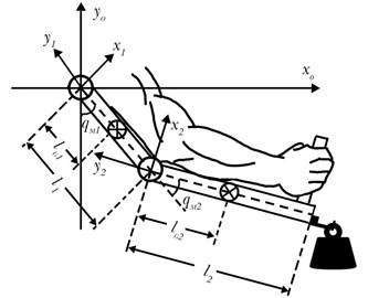
The purpose of our upper-limb exoskeleton design is to synchronize the human and the machine positions. If the exoskeleton is able to track the operator’s motion quickly and simultaneously, the deviation between the terminal position of the operator and that of the exoskeleton is very small. The model presents an interaction force as a function of the terminal position (, ). Consequently, the human-machine interaction force can be expressed as a spring model:
where is the terminal position vector of the exoskeleton; is the terminal position vector of the operator; is the matrix with stiffness coefficients of the interaction model; and is the operational force vector. The terminal position vector of the exoskeleton is related to the angles of revolute joints by the robot kinematics as shown in Eq. (4):
In practice, the human-machine force is measured by a multi-axis force/torque sensor mounted on the end effector. However, in simulation, the human-machine interaction force is modeled as a simple spring model. When desired angular positions of human () are provided, the terminal position vector of operator can be expressed as follows:
The operational forces are related to the joint torques by Jacobi transpose matrix such that:
where is the joint torque vector of operational space. Jacobi is a transpose matrix that can be expressed as:
In this system, the motor driver has highly efficient characteristics to provide feedback of the movement information. The actuated torque of motor can be acquired as:
where is the input voltage of the DC motor; is the current of the motor; is the torque constant; is the induction electromotive force constant; is the armature resistance; and is the armature inductance.
3. Controller design
3.1. Controller design for direct force control strategy
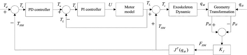
The purpose of our upper-limb exoskeleton design is to enhance the operator strength, synchronize the human and the machine positions, and minimize the human-machine interaction force. To implement these goals, a direct force control strategy consisting of two closed-loop controllers is designed. The direct force control strategy using a PD controller for the exoskeleton is shown in Fig. 2. In this system, the angles for revolute joints of the human are the desired positions which for test purposes are sinusoidal signals at a sampling frequency of 1000 Hz:
As described in Fig. 2, is the desired human-machine interaction torque. One aim of the control is to minimize the human-machine interaction torque, so that Td should be set to be zero:
where is calculated from Eq. (6). is the error between the desired and actual human-machine torques of the system. Therefore, the control law of PD controller can be written as:
where and are the proportional and differential gains, respectively. is the output of PD controller. The input of inner loop controller can be expressed as:
where is the error between the desired and the actual actuated torques of the motor. Hence, the control law of the PI controller can be described as:
where and are the proportional and integral gains, respectively. is the output voltage such that the motor generates the torque .
Fig. 2Direct force control strategy using PD controller for the exoskeleton
3.2. Design of fuzzy PD controller
Conventional PD controller has fixed gains that cannot be adjusted according to the control results of the system in real time. Therefore, it is difficult for the conventional PD controller to achieve a desired level of performance for controlling the complex system such as upper-limb exoskeleton. The conventional PD controller has to tune the gains manually according to the external load uncertainty and motion velocity variance. Otherwise, the tracking performance becomes progressively worse. To ensure the effectiveness of PD control, a popular method is to modify the linear PD controller into the nonlinear one [19]. For example,the combination of fuzzy set theory and PD controller can improve the system performance to achieve the desired effect. In this paper, the direct force control strategy using fuzzy PD controller is proposed for upper-limb exoskeleton.
The fuzzy adaptive PD controller combines the conventional PD controller and fuzzy set theory to establish a binary continuous function between the PD parameters and the torque tracking error. The gains of a PD controller can be automatically adjusted according to the deviation of torque, which plays an important role in making the fuzzy adaptive controller work on a changeable mode (that is, the external load uncertainty motion velocity variance).
3.2.1. Control objective
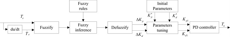
The purpose of a fuzzy PD controller is to find out the relationship between the PD gains ( and ) and the human-machine joint torque vector (), so that the controller gains can be auto-tuned in real time based on the torque error and its change rate , which are defined as follows:
The fuzzy PD controller uses and as the input variables, while the defuzzified results are used to adjust the PD gains by adding them to the initial PD gains. The structure of fuzzy PD controller is shown in Fig. 3.
Fig. 3Structure of fuzzy PD controller
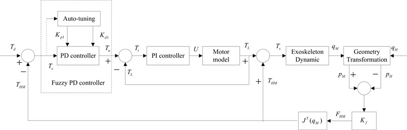
In order to achieve smooth control for the human-machine system, the direct force control strategy using fuzzy PD controller consisting of two close-loop controllers was designed, as shown in Fig. 4.
Fig. 4Direct force control strategy using fuzzy PD controller for the exoskeleton
3.2.2. Fuzzy PD controller
Fuzzy PD controller can adjust its PD parameters based on the additive change. The relationship between PD parameters and torque tracking errors is established in this paper. The inputs of the fuzzy PD controller are the torque tracking error and its change rate . Meanwhile, the outputs of the system are the additive variations of two PD parameters ( and ), which are used to adjust the PD controller by adding them to the initial parameters.
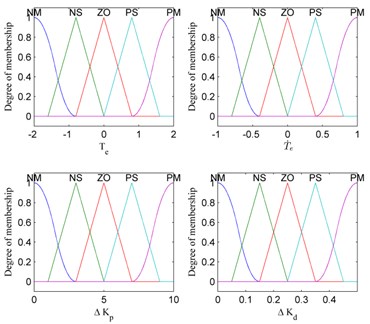
The input variables and are defined as {Negative Medium, Negative Small, Zero, Positive Small, Positive Medium}, which can be denoted by {NM, NS, ZO, PS, PM}. In addition, and are scaled to the interval of [–5, 5] and [–3, 3] for the shoulder joint of the exoskeleton and to the interval of [–2, 2] and [–1, 1] for the elbow joint. Similarly, fuzzy subset of output variables and is defined as {Negative Medium, Negative Small, Zero, Positive Small, Positive Medium}, which is also denoted by {NM, NS, ZO, PS, PM}. The terms and are scaled to the interval of [0, 10] and [0, 0.2] for the shoulder joint of the exoskeleton and to the interval of [0, 10] and [0, 0.5] for the elbow joint. The fuzzy PD controller has the form of PD structure, but the parameters are tuned by fuzzy inference, which supply a nonlinear mapping from the torque error and its change rate to PD parameters. The PD parameters of the controller are chosen using Ziegler and Nichols method [25]. Fig. 5 represents fuzzy membership functions of input and output variables for shoulder joint. Fig. 6 shows fuzzy membership functions of input and output variables for elbow joint.
Fig. 5Membership functions for shoulder joint
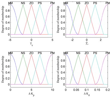
Fig. 6Membership functions for elbow joint
The fuzzy rules should be developed appropriately according to the tuning of the parameters of the PD controller, and the empirical relationship between two PD parameters and torque tracking errors should be considered in design of the fuzzy rules. To be specific, the magnitude of should increase when the system needs quick response and decrease when the undesirable oscillations need to be eliminated. Similarly, the magnitude of should increase when the deviation need to be corrected earlier and decrease when the noise is inevitably high. According to the principle of parameters tuning, the additive variables and can be adjusted while the fuzzy inference rules of the two PD parameters are determined experimentally depending on and . Consequently, the inference rules described above are built as the “If-Then” forms, which characterize the relationship between fuzzy input and output. Table 1 shows the inference rules of the fuzzy PD controller (for example, if is NM and is NM, then is NM and is NM; and if is NS and is NM, then is NM and is NS).
Mamdani inference of each rule is independent and the output constitutes of two separate nonlinear functions. It uses the appropriately designed knowledge base to evaluate the fuzzy rules and produces the output for each rule.
The defuzzification process converts the fuzzy variables to the accurate values. In order to obtain accurate results of fuzzy output, the method should be calculate the membership function results effectively. There are many types of defuzzification strategies. In this paper, centroid of area method is used for outputting the membership values.
According to the fuzzy rules, the PD gains for two joints are calculated as:
where and are the tuned gains; and are the initial PD gains for the robot joints, which can be specified based on practical experience; and and are the fuzzy inference outputs gains. The gains for the conventional PD controller are written as and .
Table 1Fuzzy inference rules of ΔKp and ΔKd
NM | NS | ZO | PS | PM | |
NM | NM | NM | NS | ZO | PS |
NM | NS | ZO | PS | PM | |
NS | NM | NS | ZO | PS | PM |
NM | NS | ZO | PS | PM | |
ZO | NM | NS | ZO | PS | PM |
NM | NS | ZO | PS | PM | |
PS | NM | NS | ZO | PS | PM |
NS | ZO | PS | PM | PM | |
PM | NS | ZO | PS | PM | PM |
4. Simulation results
The objectives of this section are to test the robustness of the fuzzy adaptive controller and the conventional PD controller and to compare the tracking performance of these controllers. Simulations in this study were carried out using Matlab. The parameters of the motor and the upper-limb exoskeleton are listed in Table 2. The parameters of the controllers are chosen using Ziegler and Nichols method [25]. Then, the optimum parameters for the PI controller can be provided as 0.0055 and 0.125. The matrix of stiffness coefficients [26] is selected as .
Table 2System parameters
Name | Symbol | Unit | value |
Mass of the robot forearm | kg | 4 | |
Mass of the robot arm | kg | 3 | |
Acceleration of gravity | m/s2 | 9.81 | |
Length of the robot forearm | m | 0.28 | |
Length of the robot arm | m | 0.2 | |
Position of the center of the robot forearm | m | 0.14 | |
Position of the center of the robot arm | m | 0.1 | |
Rotary inertia of the robot forearm | kg·m2 | 0.0708 | |
Rotary inertia of the robot arm | kg·m2 | 0.0511 | |
Torque constant | – | 1.5 | |
Induction electromotive force constant | – | 0.0125 | |
Armature resistance | Ω | 1.19 | |
Armature inductance | mH | 0.0112 |
4.1. Robustness testing: external load uncertainty
In order to test the robustness of the fuzzy adaptive controller, the mass of external load is increased from 0 to 10 kg. The frequency of the motion is 1/3 Hz. All the optimized parameters of the fuzzy and PD controllers with different load are summarized in Table 3. The initial parameters of the fuzzy PD controller are constant and the additive parameters can be adjusted automatically based on the fuzzy rules in the condition of external load uncertainty, while gains of the conventional PD controller have to be regulated manually according to the mass change. The performance of the fuzzy and the PD controllers for direct force control are compared. Figs. 7-9 show the trajectory tracking, position errors, and human-machine interaction force with different loads for each joint. It can be seen that both fuzzy and conventional PD controllers have good performance in the smooth movement stage. However, the performance of the fuzzy PD controller is better compared to that of the PD controller when the robot starts to move or changes the motion direction quickly. This means that the response time of the fuzzy PD controller is faster than that of the conventional PD controller. The actual movement trajectory can follow the desired trajectory more accurately as the fuzzy adaptive controller takes into account of the current movement state of the robot to modulate itself with load change.
Table 3PD gains for different loads
Load (kg) | , | |||
Shoulder joint | Elbow joint | |||
PD controller | Fuzzy PD controller | PD controller | Fuzzy PD controller | |
0 | 70 | 120 | 35 | 65 |
1.5 | 0.4 | 0.5 | 0.03 | |
5 | 90 | 120 | 47 | 65 |
1.6 | 0.4 | 0.5 | 0.03 | |
10 | 110 | 120 | 80 | 65 |
2.3 | 0.4 | 1.1 | 0.03 | |
Tracking performances of the force control strategy for the upper-limb exoskeleton are tested through simulation. To evaluate the comparison results, the system tracking performances are indicated by root-mean-square (RMS) error:
Fig. 7Performance of PD controller and fuzzy PD controller without load for trajectory tracking, position errors, and human-machine interaction torque
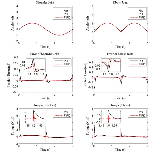
Fig. 8Performance of PD controller and fuzzy PD controller with 5 kg load for trajectory tracking, position errors, and human-machine interaction torque
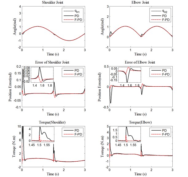
Fig. 9Performance of PD controller and fuzzy PD controller with 10 kg load for trajectory tracking, position errors, and human-machine interaction torque
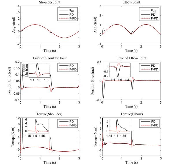
Table 4 provides the RMS errors of the human-machine position with different loads. The fuzzy PD controller has considerably less RMS error than the PD controller. Table 5 presents the RMS errors of the human -machine interaction torques with different loads. From Table 5, it can be seen that the fuzzy PD controller has a better performance in reducing the human-machine interaction torque than PD controller in all joints with different loads.
Table 4RMS error of the human-machine position with different loads
Load (kg) | Shoulder joint (rad) | Elbow joint (rad) | ||
PD controller | Fuzzy PD controller | PD controller | Fuzzy PD controller | |
0 | 0.0142 | 0.0057 | 0.0331 | 0.0137 |
5 | 0.0195 | 0.0087 | 0.0444 | 0.0207 |
10 | 0.0269 | 0.0071 | 0.0604 | 0.0170 |
Table 5RMS error of the human-machine interface torque with different loads
Load (kg) | Shoulder joint (N.m) | Elbow joint (N.m) | ||
PD controller | Fuzzy PD controller | PD controller | Fuzzy PD controller | |
0 | 0.5824 | 0.2003 | 0.2113 | 0.0607 |
5 | 0.0213 | 0.0053 | 0.0488 | 0.0127 |
10 | 1.9038 | 0.5822 | 0.4775 | 0.2307 |
4.2. Robustness testing: motion velocity variance
In the second case, for robustness evaluation of the controllers the motion frequency is decreased from 1/2 Hz to 1/6 Hz. The motion frequency values are selected from Refs. [14, 27, 28]. The PD parameters must be tuned manually based on the motion frequency value, while the fuzzy PD initial parameters are constant, and the additive parameters can be adjusted automatically according to the velocity change. The fuzzy PD parameters can be tuned adaptively in real-time based on the torque error and its change rate. All the proportional and differential gains of the fuzzy and the PD controllers for different motion frequency values are stated in Table 6.
Table 6PD gains for different motion frequency
Motion frequency (Hz) | , | |||
Shoulder joint | Elbow joint | |||
PD controller | Fuzzy PD controller | PD controller | Fuzzy PD controller | |
1/2 | 70 | 120 | 30 | 65 |
1.0 | 0.4 | 0.1 | 0.03 | |
1/3 | 70 | 120 | 35 | 65 |
1.5 | 0.4 | 0.5 | 0.03 | |
1/6 | 75 | 120 | 39 | 65 |
1.2 | 0.4 | 0.25 | 0.03 | |
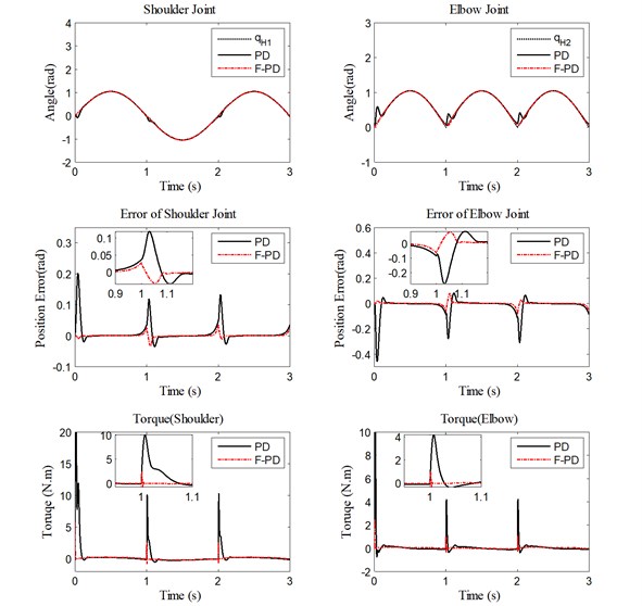
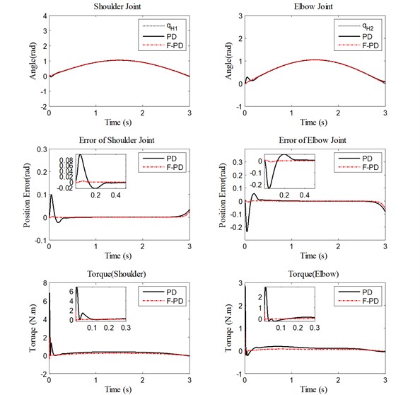
Performances of the fuzzy and the PD controllers for trajectory control are compared next. Figs. 10-12 show trajectory tracking, position errors, and human-machine interaction torque for each joint with different motion frequency. As seen in the figures, the performance of the fuzzy PD controller is better compared to the PD controller when operator starts to move or changes the motion direction quickly. The fuzzy PD controller has faster response time and settling time. The actual movement trajectory can follow the desired trajectory more closely because the fuzzy PD parameters can be tuned adaptively in real time.
Fig. 10Performance of PD controller and fuzzy PD controller under high velocity for trajectory tracking, position errors, and human-machine interaction torque
The RMS errors of the human-machine position and the human-machine interaction torque with different motion frequency values are provided in Tables 7-8. The fuzzy PD controller shows considerably less RMS errors compared to the PD controller. When the motion frequency is uncertain, it is seen that the deviations occur from the desired trajectory and the fuzzy adaptive controller produces better results than the conventional PD controller.
Fig. 11Performance of PD controller and fuzzy PD controller under medium velocity for trajectory tracking, position errors, and human-machine interaction torque
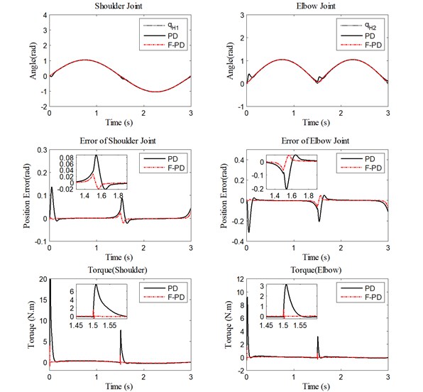
Fig. 12Performance of PD controller and fuzzy PD controller under low velocity for trajectory tracking, position errors, and human-machine interaction torque
The simulation results illustrate that the fuzzy adaptive PD controller has played a significant role in improvement of the tracking accuracy, with effective reduction in the human-machine interaction forces. In order to test the robustness of the controllers, the mass of external load and motion velocity were changed. The conventional PD controller shows a good performance only when the gains are manually tuned according to the load mass and the motion frequency. However, the fuzzy PD controller performs better and is more adaptive as its gains can be adjusted according to the load and motion frequency values, especially in the stages of the initial movement and the change in direction.
Table 7RMS error of the human-machine position with different motion frequency
Motion frequency (Hz) | Shoulder joint (rad) | Elbow joint (rad) | ||
PD controller | Fuzzy PD controller | PD controller | Fuzzy PD controller | |
1/2 | 0.0132 | 0.0034 | 0.0314 | 0.0081 |
1/3 | 0.0195 | 0.0048 | 0.0448 | 0.0114 |
1/6 | 0.0276 | 0.0064 | 0.0634 | 0.0152 |
Table 8RMS error of the human-machine interface torque with different motion frequency
Motion frequency (Hz) | Shoulder joint (N.m) | Elbow joint (N.m) | ||
PD controller | Fuzzy PD controller | PD controller | Fuzzy PD controller | |
1/2 | 0.4325 | 0.1817 | 0.1635 | 0.0469 |
1/3 | 1.4854 | 0.1918 | 0.5671 | 0.0555 |
1/6 | 1.8456 | 0.2118 | 0.6557 | 0.0697 |
5. Conclusions
Direct force control for 2-DOF upper-limb exoskeleton, under the actuation of motor, was explored in this study. The direct force control strategy consists of two closed-loop controllers, including a PD controller and a PI controller, to synchronize the human-machine positions and to minimize the human-machine interaction forces. The fuzzy set techniques are used in combination of the PD controller to improve the system performance, especially when the operator starts to move or changes the direction of the motion. The simulation results show that fuzzy PD controller gives better tracking performance, such as less RMS error in human-machine position synchronization and human-machine interaction force minimization. Furthermore, the fuzzy controller can adaptively regulate its parameters according to the external load mass and the motion frequency, while the conventional PD controller must tune its parameters manually with different motion velocity and mass of the external load.
In the future, our work will involve obtaining a better trajectory tracking performance by combining the fuzzy PD controller with other control techniques, such as neural network and genetic algorithm. Furthermore, in order to improve the control effect, the friction compensation and gravity compensation will also be taken into account.
References
-
Lee H., Yu S., Lee S., Han J., Han C. Development of human-robot interfacing method for assistive wearable robot of the human upper extremities. Proceedings of the SICE Annual Conference, 2008, p. 1755-1760.
-
Daly J. J., Hrovat K., Pundik S., Sunshine J., Yue G. fMRI methods for proximal upper limb joint motor testing and identification of undesired mirror movement after stroke. Journal of Neuroscience Methods, Vol. 175, Issue 1, 2008, p. 133-142.
-
Kiguchi K., Hayashi Y. An EMG-based control for an upper-limb power-assist exoskeleton robot. IEEE Transactions on Systems, Man, and Cybernetics – Part B: Cybernetics, Vol. 42, Issue 4, 2012, p. 1064-1071.
-
Hessinger M., Müller R., Werthschützky R., Pott P. P. Tool position control of an upper limb exoskeleton for robot-assisted surgery. IFAC-PapersOnLine, Vol. 28, Issue 20, 2015, p. 195-200.
-
Lee B. K., Lee H. D., Lee J. Y., Shin K., Han J. S., Han C. S. Development of dynamic model-based controller for upper limb exoskeleton robot. IEEE International Conference on Robotics and Automation, 2012, p. 3173-3178.
-
Vallery H., Van Asseldonk E. H. F., Buss M., Van Der Kooij H. Reference trajectory generation for rehabilitation robots: complementary limb motion estimation. IEEE Transactions on Neural Systems and Rehabilitation Engineering, Vol. 17, Issue 1, 2009, p. 23-30.
-
Li Z., Wang B., Sun F., Yang C., Xie Q., Zhang W. SEMG-based joint force control for an upper-limb power-assist exoskeleton robot. IEEE Journal of Biomedical and Health Informatics, Vol. 18, Issue 3, 2014, p. 1043-1050.
-
Ju M.-S., Lin C.-C.-K., Lin D.-H., Hwang I.-S., Chen S.-M. A rehabilitation robot with force-position hybrid fuzzy controller: hybrid fuzzy control of rehabilitation robot. IEEE Engineering in Medicine and Biology Society, Vol. 13, Issue 3, 2005, p. 349-358.
-
Volpe R., Khosla P. A theoretical and experimental investigation of explicit force control strategies for manipulators. IEEE Transactions on Automatic Control, Vol. 38, Issue 11, 1993, p. 1634-1650.
-
Hayashibara Y., Tanie K., Arai H., Tokashiki H. Development of power assist system with individual compensation ratios for gravity and dynamic load. IEEE/RSJ International Conference on Intelligent Robots and Systems, 1997, p. 640-646.
-
Kazerooni H. Human/robot interaction via the transfer of power and information signals. IEEE International Conference on Robotics and Automation, Vol. 3, 1989, p. 1632-1647.
-
Silawatchananai C., Parnichkun M. Force control of an upper limb exoskeleton for virtual reality using impedance control. IEEE International Conference on Robotics and Biomimetics, 2011, p. 2342-2347.
-
Meng W., Liu Q., Zhou Z., Ai Q., Sheng B., Xie S. S. Recent development of mechanisms and control strategies for robot-assisted lower limb rehabilitation. Mechatronics, Vol. 31, 2015, p. 132-145.
-
Bingül Z., Karahan O. A Fuzzy logic controller tuned with PSO for 2 DOF robot trajectory control. Expert Systems with Applications, Vol. 38, Issue 1, 2011, p. 1017-1031.
-
Malki H. A., Feigenspan D. DC motor control using fuzzy proportional-derivative technique. Proceeding of NAFIPS/IFIS/NASA, 1994, p. 373-374.
-
Alavandar S., Nigam M. J. Fuzzy PD+I control of a six DOF robot manipulator. Industrial Robot: An International Journal, Vol. 35, Issue 2, 2008, p. 125-132.
-
Meza J. L., Santibáñez V., Soto R., Llama M. A. Fuzzy self-tuning PID semiglobal regulator for robot manipulators. IEEE Transactions on Industrial Electronics, Vol. 59, Issue 6, 2012, p. 2709-2717.
-
Lewis F. L. Nonlinear network structures for feedback control. Asian Journal of Control, Vol. 1, Issue 4, 1999, p. 205-228.
-
Yu W., Rosen J. Neural PID control of robot manipulators with application to an upper limb exoskeleton. IEEE Transactions on Cybernetics, Vol. 43, Issue 2, 2013, p. 673-684.
-
Wu C. J., Lee T. L., Fu Y. Y., Lai L. C. Auto-tuning fuzzy PID control of a pendubot system. Proceedings of the 4th IEEE International Conference on Mechatronics, 2007, p. 8-10.
-
Chen C. H., Liu T. K., Chou J. H. A novel crowding genetic algorithm and its applications to manufacturing robots. IEEE Transactions on Industrial Informatics, Vol. 10, Issue 3, 2014, p. 1705-1716.
-
Plius M. P., Yilmaz M., Seven U., Erbatur K. Fuzzy controller scheduling for robotic manipulator force control. International Workshop on Advanced Motion Control, 2012.
-
Mamdani E. H., Sc M. Application of fuzzy algorithms for control of simple dynamic plant. Proceedings of the Institution of Electrical Engineers, Vol. 121, Issue 12, 1974, p. 1585-1588.
-
Gomonwattanapanich O., Pattanapukdee A., Mongkolwongrojn M. Compensation and estimation of friction by using extended Kalman filter. SICE-ICASE International Joint Conference, 2006, p. 5032-5035.
-
Ziegler And Nichols J. G. N. B. Optimum settings for automatic controller. Transactions of the ASME, Vol. 64, Issue 1, 759, p. 768-1942.
-
Lie Yu, Jianbin Zheng, Yang Wang, Enqi Zhan, Qiuzhi Song Direct force control for human-machine system with friction compensation. Kybernetes, Vol. 45, Issue 5, 2016, p. 760-771.
-
Sunan Huang, Kok Kiong Tan Intelligent friction modeling and compensation using neural network approximations. IEEE Transactions on Industrial Electronics, Vol. 59, Issue 8, 2012, p. 3342-3349.
-
Vitiello Valentina, Tornambe Antonio Adaptive compensation of modeled friction using a RBF neural network approximation. Proceedings of the 46th IEEE Conference on Decision and Control, New Orleans, LA, USA, 2007.
Cited by
About this article

