Abstract
Coal augers is a new type of mining equipment used in thin coal seam, and directional drilling performance of its drilling tools becomes the key issue in the equipment service life and drilling efficiency. The drilling test bench of a three-bit coal auger is constructed to study vibration and deflection performance of its drilling tools in this paper. Based on some reasonable simplifications and hypotheses of drilling tools, simulation model of a three-bit coal auger is established to analyze its vibration and deflection performance with different drilling depths. Then a novel drill rod stabilizer is designed and the simulation model of a three-bit coal auger with this stabilizer is constructed compared with a normal coal auger to study vibration and deflection performance of drilling tools, which provides scientific basis for stabilizers’ arrangement form. Research shows that: the simulation results accords with test results, which verifies correctness and rationality of simulation; vibration and deflection of drilling tools become greater with drilling depth increasing; drill rod stabilizers can effectively reduce drilling tools’ vibration and deflection, and are arranged every 5 drill rods and air pipes which is optimal decision.
1. Introduction
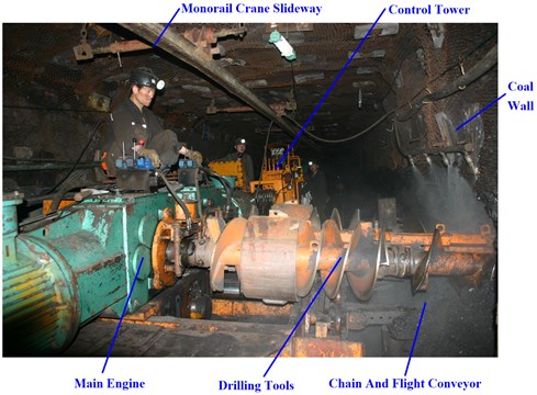
Coal augers [1-3] is a new type of mining equipment used in thin coal seam, realizing coal mining in working surface without one and support, which has a promising prospect of application, and whose overall structure and drilling field are respectively shown in Fig. 1 and Fig. 2.
Fig. 1Overall structure of coal auger
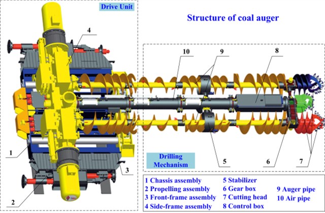
Fig. 2Drilling field of coal auger
However, poor working conditions of coal auger could cause severe drilling deflection, owing to self-structure of drilling tools, drilling depth, drilling load, collision with coal wall, friction resistance and so on during the process of practical drilling, which has become an issue serious enough to affect drilling depth and drilling efficiency [4-6]. In addition, complex forces and serious deformation of drilling tools after deflecting could easily cause dangerous accidents, such as sticking of drilling tools, droping out of drilling rods, etc., which is a serious constraint to application and development for coal auger. Therefore, the paper involves experiment and simulation conducted on deflection and vibration of three-bit drilling tools during the process of drilling, and proposes a novel stabilizer of three-bit drilling tools to weaken and control deflection and vibration, which provides scientific basis for directional drilling of coal auger.
Few of domestic and foreign scholars focus on coal augers at present, but most on relevant areas, which can provide guidance and reference for the research of this paper. Millheim and Apostal [7, 8] proposed that the contact, torque and friction between rotational drilling tools and coal wall have important influence on vibration performance of coal auger drilling tools by establishing three-dimensional finite element and dynamics analysis model with inertia force and friction force firstly introduced. Dunayevsky and Abbassian [9, 10] first presented that drill rod not only rotated around its own axis but also generated whirling motion, and its whirling frequency was far less than its natural frequency, which developed a new direction for drilling rod’s dynamics analysis. Dykstra [11, 12] established coupled torsional-axial vibration mechanical model of drilling tools in the vertical well and conducted experimental research on dynamic characteristic of cutting heads and drilling rods, which proved that drilling rods’ mass unbalance, composed of eccentricity, initial bending, eccentric wear and so on, was one of the main causes of their lateral vibration. Rae [13] defined torque and drilling resistance in practice and solved a series of problems with drilling depth increasing from successful case of CAPTION oil field in the site analysis. Liufeng [14] analyzed the transformation of drilling rods from stable state to nonlinear and buckling under different constraint conditions in the horizontal drilling well by using finite element method and taking into account the influence of gravity and load, which showed that buckling deformation of drilling rods was a transformation from the local buckling to the global, and it is mainly cyclical variations that constrain force, bending moment and buckling displacement on buckling drill rods against the well wall, furthermore, gravity could effectively slow horizontal buckling and the effect of different boundary constraint conditions on drilling pipes buckling could not be ignored, while that of torque could be done. Birades [15] held that position change of cutting heads was caused by increasing well diameter and friction, while deflection of drilling tools mainly done by the former factor, and there are two modes, continuous contact and continuous collision between drilling tools and well walls through setting up the model of drilling tools and well walls. Sahebkar [16] built nonlinear drilling system model under propulsion action in the inclined well using perturbation technique, established nonlinear governing equations of motion based on the Hamilton principle, and solved the equation by means of multiscale method, where steady response and stable domain were achieved, and many nonlinear factors impacting drilling tools’ natural frequency were analyzed in detail, including rotating speed, propulsion, unbalance mass, nonlinear fluid force and so on. Cui Xinxia [17] held that drilling tools produced vertically and horizontally torsional coupled vibrations during drilling process, because of structure complicated coal seam, elastic deformation of drilling tools and unbalanced acting force between cutting picks and coal wall, resulting in deflection of drilling tools, through vibration of cutting transmission system was simulated under a coal auger drilling different kinds of coal rock. Gao [18, 19] studied the influence of the parameters on the coal loading performance of the shearer drum using a three-dimensional (3D) discrete element method (DEM) simulation in the current study, and obtained the trends of the influential parameters. Yang [20-22] established an interference model of rotation-drilling cutting to decrease the wear and determine the key factors that influence the wear performance of conical picks for coal auger, and carried out laboratory rotary-drilling cutting experiments with different cutting angles and rotation angles using low-hardness alloy substituting high-hardness alloy, which provided technical support for a reasonable selection of conical pick installation angles for coal auger.
These literatures studied drilling tools’ vibration effects of various parameters, including boundary condition, drilling load, structural parameter of drilling tools and so on, but it is scarcely reported on the whole body vibration and deflection of a coal auger drilling tools, which results that their vibration and deflection is not easy to effectively predict, then application and development of coal auger is hindered. In addition, there is currently no effective measure to control deflection [23-27], and research on stabilizers arrangement form only confines to theoretical analysis with little attention to corresponding simulation research. Aiming at this situation, the article firstly builds drilling test bench of a three-bit coal auger’ drilling tools and conducts the experiment to study their vibration and deflection performance; it secondly establishes the rigid-flexible coupling simulation model of a three-bit coal auger’ drilling tools and analyzes their vibration and deflection performance with different drilling depth; it finally designs a novel drill rod stabilizer, constructs simulation model of a three-bit coal auger with the stabilizer to study vibration and deflection performance for stabilizers’ arrangement form, which provides scientific basis for effective control of drilling tools’ vibration and deflection.
2. Experiment
2.1. Experimental material
In order to guarantee accuracy of experiment, laboratorial coal specimens should reflect all characteristics of natural coal, based on coal characteristics playing a decisive role on actual drilling. Cement, sand and coal powder are selected as raw material in proportion to make laboratorial coal specimens in the paper, according to study results of main parameters of natural coal, such as density, elastic modulus, Poisson’s ratio and compressive strength and so on, and the approximate relationship between differently fitting proportion and compressive strength of laboratorial coal specimens in the literature [28].
Cutting head of experimental mechanism is 230 mm in diameter, and coal auger MZY425 is 550 mm, whose similarity ratio is 2.4, namely similarity coefficient [29] is 1/2.4. Compressive strength of laboratorial coal specimens should be calculated based on that of natural coal before making it. Computation formula is as follows:
where is the compressive strength of laboratorial coal specimens, MPa; is the compressive strength of natural coal, MPa; is the similarity coefficient, 1/24.
Compressive strength of natural coal chosen for this article is 12.42 MPa, while the corresponding of laboratorial coal specimens is 2.07 MPa. Compressive strength of coal specimens is calculated based on approximate relationship between differently fitting proportion and compressive strength of laboratorial coal specimens. Computation equation is as follows:
where is the ratio of sand and cement.
Based on the sand, water and cement as binder, coal specimens about 50 mm in diameter and 100 mm high is made by mixing cement, sand and water with proportion of 1:4:0.65. Uniaxial compressive strength tests are conducted on the SANS testing machine, obtaining performance of coal specimens including stress-strain curve, elastic modulus, Poisson ratio and compressive strength and so on. SANS test system is shown in Fig. 3. Original coal specimen and the broken are shown in Fig. 4. Therefore, based on production test report after the test, the compressive strength of coal specimens made by mixing cement and sand with the proportion of 1:4 is 2.07 MPa.
Fig. 3SANS test system
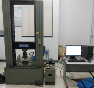
Fig. 4Coal specimens picture
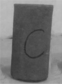
a) Original picture of coal specimen
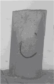
b) Broken picture of coal specimen
2.2. Experimental method and process
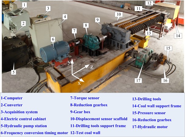
It is mainly studied that vibration, deflection and loads of coal auger’ drilling tools during the process of drilling in this paper. The drilling test bench of a three-bit coal auger is constructed, as shown in Fig. 5, where frequency variable motor is used to provide torque for drilling tools breaking coal by transmission actuator, and hydraulic motor to provide propulsion for drilling tools’ feed movement by rack and pinion mechanism. Torque, propelling resistance and deflection displacement of each measuring point for drilling tools when drilling coal wall are respectively obtained by means of the digital torque sensor GB-DTS200, the pressure transducer JNBP-10 MPa and the electric eddy transducer HZ-891, providing experimental data for deflection simulation analysis of coal auger’ drilling tools.
The experiment could not meet drilling tools’ size and drilling depth of actual coal auger with the limitation of space and conditions in this experiment. Therefore, it is studied that deflection and deformation trend of drilling tools during the process of drilling with only drilling depth of one, two, three and four sections length for drilling rod, in order to look for relationship between deflection, vibration and drilling depth, then put forward a corresponding directional control strategy.
Fig. 5Drilling test bench of coal auger
2.3. Experimental results and analyses
Deflection and vibration of three-bit drilling tools under different drilling depth are mainly studied in the experiment; in addition, their resistance and torque are measured, where drilling depth is respectively one, two, three and four drilling rods, hardness of laboratorial coal specimen 2.07, rotate speed of drilling tools 60 r/min.
2.3.1. Deflection and vibration under different drilling depth
Displacement detector could monitor real-time displacement changes in each measuring point of drilling tools in the experiment. Therefore, deflection displacement is monitored under different drilling depth. Taking drilling depth of four drill rods as example, time-displacement curves of each measuring point are shown in Fig. 6. From Fig. 6, displacement of each measuring point shows obvious changes after five seconds drilling coal, upon further analysis, deflection displacement values of each measuring point in all direction could be obtained, using mean displacement to characterize deflection performance, and standard deviation displacement to characterize vibration performance. As shown in Fig. 6(b), deviation displacement of the left drilling rod in measuring point 2 direction is 3.02 mm and the direction is 5.18 mm. After data processing, vibration displacement direction is 1.87 mm and the direction is 1.69 mm. Deflection and vibration displacement in each measuring point of drilling tools under different drilling depth would be obtained by this method.
In order to further investigate influence of drilling depth on deflection and vibration displacement, the article focuses on maximal deflection and vibration displacement value of drilling rods and hair dryers in and direction to achieve their relationship, as shown in Fig. 8.
Fig. 6Time-displacement curves of three-bit drilling tools with 4 drill rods
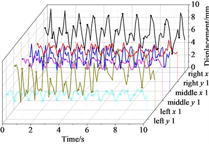
a) Displacement in measuring point 1
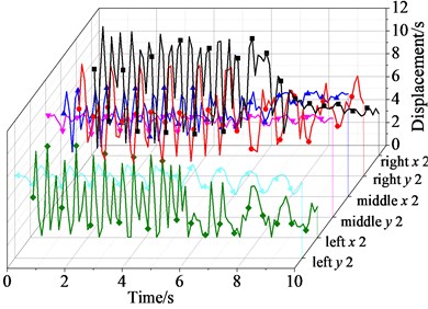
b) Displacement in measuring point 2
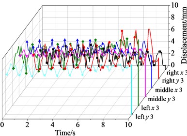
c) Displacement in measuring point 3
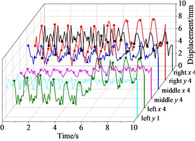
d) Displacement in measuring point 4
Fig. 7Deflection displacement statistic law of three-bit drilling tools under different drilling depth
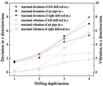
a) Deviation and vibration in direction
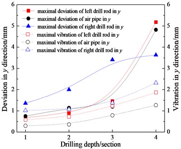
b) Deviation and vibration in direction
From Fig. 7, the deflection and vibration displacement value of drill pipes and air pipes in and direction increase as drilling depth increasing; according to previous analysis, deflection and vibration displacement value of air pipe are smaller than left and right drill rod, and deflection and vibration displacement value of left drill rod in direction slightly greater than right drill rod, while that in direction is slightly smaller than right drill rod. Therefore, deflection and vibration of drilling tools majorly take place in drill rods during process of drilling, which is mainly caused by drilling torque, propulsion and conveying coal load of drilling tools on drill rods.
2.3.2. Drilling load under different drillings depth
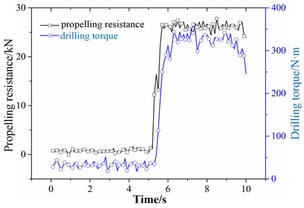
Pressure detector and torque sensor could respectively monitor real-time propelling resistance and drilling torque change of drilling tools in the experiment. Therefore, propelling resistance and drilling torque are monitored under different drilling depth. Taking drilling depth of four sections length for drilling rods as example, propelling resistance and drilling torque curves along with time are shown in Fig. 8. From Fig. 8, propelling resistance and drilling torque on drilling tools increase sharply after second seconds drilling coal, while propelling resistance and drilling torque on drilling tools become stable after five seconds drilling coal.
Fig. 8propelling resistance and drilling torque curve along with time of three-bit drilling tools with 4 drill rods
Propelling resistance and drilling torque statistics of three-bit drilling tools under different drilling depth are shown in Fig. 9, upon further analysis, influence of drilling depth on the propelling resistance and drilling torque of drilling tools would be obtained.
Fig. 9Relationship of three-bit drilling tools propelling resistance, drilling torque and drilling depth
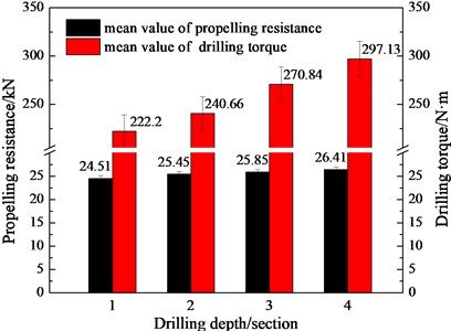
From Fig. 9, propelling resistance and drilling torque value on drilling tools show an increased trend with drilling depth increasing during the process of drilling, while propelling resistance and drilling torque no evident change trend.
3. Simulation
3.1. Simulation model
Drilling tools are acted by a complex contribution of their own weight, propelling resistance, drilling torque, impact contact force with hole wall and frictional resistance from coal during the process of coal auger drilling. The article focuses on drilling tools and puts forward following basic assumptions [30, 31]:
(1) drilling-hole cross section of single drilling rod is circular, and its size does not change with time;
(2) cutting head, connector of cutting head and gear box are rigid bodies, drilling rod is flexible body, and central axis of drilling tool in initial position and axis of drilling hole are coincidence;
(3) frictional collision of drill rod applying to hole wall is likely to be polydirectional and random, then drilling rod would be pushed back with equal force by hole wall;
(4) lateral movement of drilling tools is resolved into two components, horizontal direction and vertical direction ;
(5) partial construction of drilling tools are reasonably predigested, including connectors, boxes, pin shafts, bearings and so on.
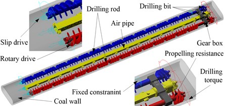
Based on above assumptions, a three-dimensional solid model of drilling tools is imported into ADAMS multi-body dynamics software, then to set properties, add constraints, apply drive and loads, and define contact, finally a rigid-flexible coupling model of three-bit coal auger’s drilling tools is received, as shown in Fig. 10.
Fig. 10Simulation model
3.2. Results and analysis of simulation
3.2.1. Influence of drilling depth on deflection and vibration
Drilling depth increases constantly along with drilling rod and air pipe segment-by-segment increasing during the process of coal auger drilling, resulting in the whole rigidity of drilling tools reducing. Therefore, resistance capacity of drilling tools to deform becomes down under the same load condition, leading to deflection phenomenon becoming more complicated. It is drilling depth of one, two, three and four sections length for drilling rods where deflection and vibration of coal auger’s drilling tools is measured and analyzed in the experiment, while drilling depth in the practical production application is much longer than four drilling rods. In order to explore deflection and vibration during the process of coal auger long-distance drilling, deflection and vibration under different drilling depth is simulated and analyzed in this section in anticipation of gaining the relationship between drilling depth and deflection performance of three-bit drilling tools.
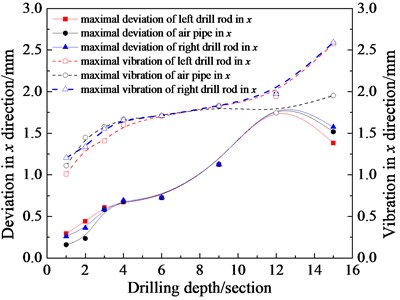
Drilling depth of one, two, three, four, nine, twelve and fifteen sections length for drilling rods, for example, are simulated and analyzed, gaining corresponding deflection and vibration of drilling tools. According to further statistics, maximal deflection and vibration of left, right drilling rod and air pipe in , direction, it is gained that the relationship between deviation, vibration and drilling depth, comparing with test results, as shown in Fig. 11.
From Fig. 11, deviation and vibration tendency of left, right drill rod is quite similar to air pipe’s. From Fig. 11(a), deviation of left, right drill rod and air pipe in direction first increases and then decreases with drilling depth increasing, up to 12 drill rods in direction where deviation value reaches the maximum; while their vibration in x direction increases constantly with drilling depth increasing, after to 7 drilling rods where vibration of air pipe approximately trends to be stable. From Fig. 11(b), deviation and vibration of left, right drill rod and air pipe in direction increase constantly with drilling depth increasing, up to 12 drill rods in y direction where vibration value reaches the maximum, then becomes stable. Deviation and vibration of air pipe in and direction is less than drill rods’ in view of sectional dimension of air pipe and space between air pipe and coal wall. Inferred by former research, deviation and vibration tendency of air pipe gradually tends to a stable value when drilling depth coming to a certain value. Finally, based on above analysis and findings with the experiment, emulational results approximately agree with the experimental, proving its rationality and correctness.
Fig. 11Relationship between deviation, vibration and drilling depth
a) Deviation and vibration in direction
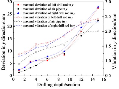
b) Deviation and vibration in direction
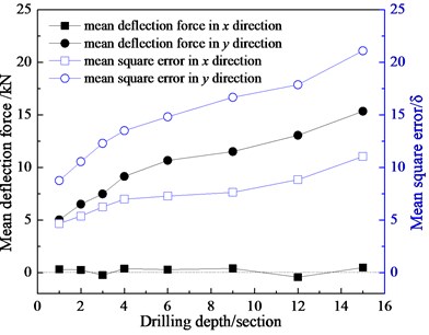
Drilling depth would affect deflection force of three-bit drilling tools, as shown in Fig. 12. From Fig. 12, deflection force of drilling tools in x direction occurs in vicinity of zero value going up and down, having little change with drilling depth; while their deflection force in direction increase with drilling depth. Therefore, anti-deflection capability of three-bit drilling tools in direction is apparently better than that in direction, and anti-deflection force correcting deflection of drilling tools in y direction gradually increased with drilling depth.
Fig. 12Influence of drilling depth on deflection force of three-bit drilling tools
3.2.2. Deflection and vibration of three-bit 12 drilling rods
In the case of three-bit coal auger under drilling depth of 12 drilling rods, its deflection and vibration is simulation studied and analyzed, receiving its statistical regularities from each measuring point in , direction, as shown in Fig. 13, where using mean displacement to characterize deflection performance, and mean square error of displacement to characterize vibration performance.
Fig. 13Deflection (D) and vibration (V) of three-bit drilling tools with 12 drill rods
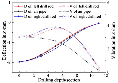
a) Deflection and vibration in direction
b) Deflection and vibration in direction
From Fig. 13(a), three-bit drilling tools in direction deflects slightly, and deflection of left, right drill rod and air pipe are relatively consistent. The rate of displacement change of measuring points at both ends of drilling tools is significantly lower than that on middle measuring points on account of cutting head constrained with coal wall and driving end, and fixed by transmission case, which shows that drilling tools on the cutting head end and on the driving end have greater anti-deflection capability. Maximum vibration amplitude of three-bit drilling tools is at middle measuring point 5, not at cutting head, affected by rotational self-motion and torque load. Vibration amplitude of middle air pipe in direction has the tendency of positive correlation with distance from measuring points to driving end, as a result of influence of structure itself, in addition, without torque load and rotational motion.
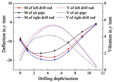
From Fig. 13(b), deviation and vibration of three-bit drilling tools in y direction first increases and then decreases with distance from measuring points to driving end because of cutting head in diameter larger than drill rod, up to the measuring point 4 and 5 where deviation and vibration value reaches the maximum. Deviation and vibration of left, right drill rod under action of rotational motion and torque load is larger than that of air pipe. Furthermore, deviation of drilling tools in y direction is greater than that in direction, comparing Fig. 13(a).
Overall, three-bit drilling tools of 12 drill rods, especially the fourth, fifth drill rod, frequently collide with coal wall, whose deflection in direction is far greater than that in direction, and whose maximum deflection locates in the middle of drill rods.
Both cutting head and drill rod collide with coal wall as a result of deflection bending of drilling tools. In order to obtain deflection force applied to drilling tools during drilling process, collision force of drilling tools with coal wall in , direction is figured out, as shown in Fig. 14. From Fig. 14(a) and (c), left drill rod and cutting head, and right drill rod and cutting head, frequently collide with coal wall, for another, collision force applied to left, right drill rod is going in opposite directions, which means that collision forces applied to drilling tools in direction are equal and opposite, only resulting in slight deflection and vibration of drilling tools in direction without affecting overall drilling tools moving forward. From Fig. 14(b) and (d), collision force of drilling tools is always in negative direction owing to frequent collision of drilling tools and the bottom of coal wall holes, so that drilling tools continuously generates force in the vertically downward on the coal wall holes, which might eventually lead to drilling tools deflecting down in direction.
Fig. 14Collision force in x, y directions of three-bit drilling tools with 12 drill rods
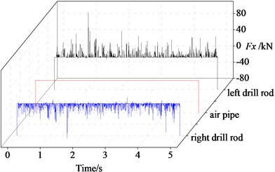
a) Collision force in direction
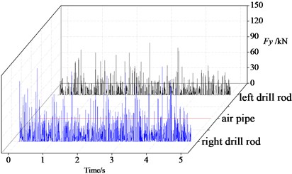
b) Collision force in direction
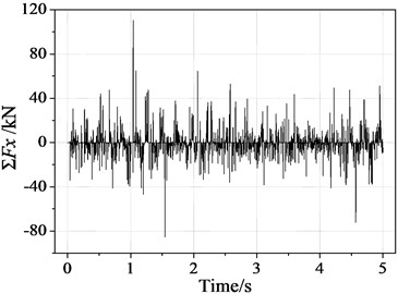
c) Resultant force in direction
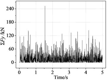
d) Resultant force in direction
4. Stabilizer
According to results of experiment and simulation and combining with engineering application, drilling depth increasing blindly not only cannot improve drilling efficiency, instead would aggravate vibration and energy loss. Based on the existing coal auger and combined with research findings from related subjects, the paper proposes a method to reduce deflection and vibration of drilling tools, and then carries on stimulation analysis, which achieves the goal for directional drilling of coal auger and improving drilling efficiency.
4.1. Stabilizer design
A stabilizer of three-bit drilling tools is now designed taking three-bit coal auger as the research object, which is mainly composed of left, right stable ring, air tunnel and connecting pin, as shown in Fig. 15.
Thereinto, stable rings slightly are larger in diameter than outer margin of drilling rods, and arranged respectively with homocentric drill rods, playing an important role in confining lateral deformation of drilling tools. Stabilizers would restrict deflection and deformation of drill rods within a certain range, fixed on air tunnel broadsides by connecting pins, finally reaching the goal of improving the whole rigidity and stability of drilling tools, and providing guarantees for directional drilling.
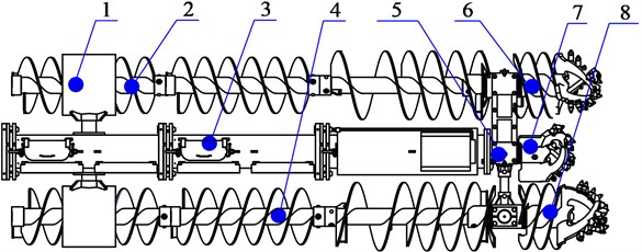
Stabilizer of three-bit drilling tools, belonging to rigid structure, limits drilling rods’ displacement with two stable rings, as rigid displacement limiters, so as to further achieve the goal of restricting deflection between drilling rods and air pipes. Three-bit drilling tools arranged a stabilizer at three drilling pipes intervals is shown in Fig. 16.
Fig. 15Stabilizer component of three-bit drilling tools
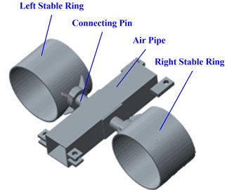
Fig. 16Three-bit drilling tools structure arranged a stabilizer at three drilling pipes intervals: 1 – drill rod stabilizer; 2 – left drilling rods; 3 – air pipe; 4 – right drilling rods; 5 – gear box; 6 – left drilling bit; 7 – middle drilling bit; 8 – right drilling bit
4.2. Influence of stabilizer on deflection and vibration
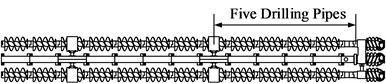
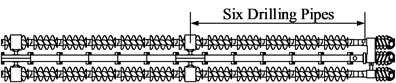
Deflection of drilling tools is increasing with coal auger ever drilling. Stabilizers of drilling rod could be used to control and weaken deflection and vibration of drilling tools under long distance drilling. Stabilizers are settled so reasonably that vibration of drilling tools could be significantly reduced without losing transfer efficiency of coal, meanwhile, energy loss could be reduced and drilling efficiency could be improved. In order to outstand effects of stabilizers more intuitively and arrange stabilizers more reasonably, then to obtain influence of stabilizers’ arrangement form on deflection, vibration of drilling tools and acting force between drilling tools and coal wall, the paper focuses on three-bit drilling tools with 12 drill rods and arranges a stabilizer respectively at three, four, five and six drilling pipes intervals, as shown in Fig. 17, and studies influence rule of stabilizers’ arrangement form on deflection, vibration of drilling tools. Deflection and vibration of drilling tools under different stabilizers’ arrangement forms are analyzed on the basis of simulation results in this paper, so it is received that deflection, vibration and deflection force law of three-bit drilling tools under different stabilizer arrangement forms, as shown in Fig. 18 and 19, where stabilizers’ arrangement form “0” means that without stabilizers, and “1” to “4” in turn means arrangement forms at 3 to 6 drill rods intervals.
From Fig. 18, maximal deflection and vibration of three-bit drilling tools in , direction reduce gradually with a number increase of stabilizers; the number of stabilizers increasing after respectively spaced five drill rods arranging a stabilizer, has a little influence on maximal deflection and vibration of three-bit drilling tools in direction. Therefore, stabilizers’ arrangement form “2”, “3” and “4” would be able to effectively control the deflection and vibration of three-bit drilling tools.
From Fig. 19, deflection force MV (mean value) of three-bit drilling tools in direction alternates positively and negatively with a number increase of stabilizers, while deflection force in direction increases gradually because of arrangement form and number of stabilizers having a significant impact on the overall weight and stress of drilling tools. MSE (mean square error) of deflection force in , direction has a tendency of decreasing with stabilizers increasing, and minimal mean square error is achieved at stabilizers’ arrangement form “2”. Therefore, stabilizers’ arrangement form “2” and “4” would be able to effectively control deflection force of three-bit drilling tools, but arrangement form “4”, due to stabilizers in excess, would affect the whole weight of drilling tools and efficiency of coal transfer.
Fig. 17Arrangement form of drill rod stabilizer in three-bit drilling tools
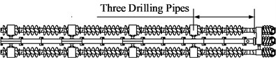
a) Arrangement form 1
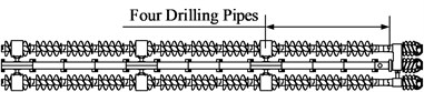
b) Arrangement form 2
c) Arrangement form 3
d) Arrangement form 4
Fig. 18Deflection and vibration law of three-bit drilling tools under different stabilizer arrangement forms
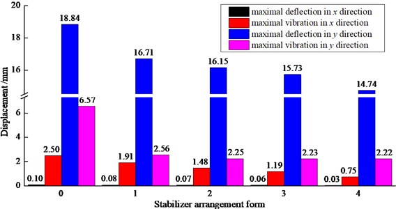
Fig. 19Deflection force law of three-bit drilling tools under different stabilizer arrangement forms
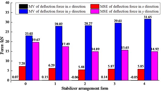
Synthesizing the above analysis, every parameter of drilling tools is comparatively better under stabilizers’ arrangement form “2”, which is spaced 5 drilling pipes arranging a stabilizer, based on deflection and vibration of drilling tools under different stabilizer arrangement forms, and according to number influence of stabilizers to deflection force of drilling tools in direction. Using this form, deflection and vibration of drilling tools in direction respectively decreases by approximately 30 % and 40 %, while that in direction respectively decreases by 14.3 % and 65.7 %, in addition, stabilizers have little impact on the overall force of drilling tools and transfer efficiency of coal. Therefore, imbalance of deflection between each row of drill rod is restrained very well in this form, anti-deflection capability and stability of the whole drilling tools is significantly improved.
5. Conclusions
Taking three-bit coal auger as research object with existing conditions, the paper involves experiment conducted on deflection, vibration performance and drilling load change law of drilling tools with drilling depth of one, two, three and four sections length for drill rod. Based on some reasonable simplifications and hypotheses of drilling tools, the paper researches on deflection and vibration performance of drilling tools under drilling depths of one, two, three, four, nine, twelve and fifteen sections length for drill rods, by building a simulation model of three-bit drilling tools. Then the paper designs a drill rod stabilizer and makes simulation study on three-bit drilling tools with stabilizers and analyzes influence on vibration and deflection performance of drilling tools. We draw the following conclusions:
1) In the drilling experiment, deflection and vibration displacement value of drilling tools increase gradually as drilling depth increasing, and deflection and vibration displacement value of air pipe are smaller than left, right drill rod, while drilling loads have no evident change trend. Therefore, deflection and vibration of drilling tools majorly takes place in drill rods during the process of drilling, which is mainly caused by drilling torque, propulsion and load of drilling tools conveying coal on drill rods.
2) Deviation and vibration tendency of drilling tools are quite similar according to simulation study on deflection and vibration with different drilling depths. Deviation of drilling tools in direction first increases and then decreases with drilling depth increasing, up to 12 drill rods in direction where deviation value reaches the maximum, while their deviation in direction increase constantly with drilling depth increasing. And their vibration in and direction first increases and then gradually tends to a stable value. Emulational results approximately agree with the experimental.
3) Based on simulation study on deflection and vibration of three-bit coal auger with 12 drill rods, collision forces applied to drilling tools in direction are equal and opposite, resulting in slight deflection and vibration of drilling tools in direction without affecting overall drilling tools moving forward; while collision force of drilling tools is always in negative direction owing to frequent collision of drilling tools and the bottom of coal wall holes, eventually leading to drilling tools deflecting down in direction. Deflection and vibration of drilling tools in direction is far greater than that in direction, whose maximal deflection locates in the middle of drilling tools.
4) Spaced 5 drill rods and air pipes arranging a stabilizer, as the best arrangement form, deflection and vibration of drilling tools in direction respectively decreases by approximately 30 % and 40 %, while that in direction respectively decreases by 14.3 % and 65.7 %, in addition, stabilizers have little impact on the overall force of drilling tools and transfer efficiency of coal.
References
-
Senyur M. G., Cengiz A. K. Auger mining of thin seams at Zonguldak colliery/Turkey. Journal of Mines Metals and Fuels, Vol. 51, Issue 11, 2003, p. 356-359.
-
Lukhele M. J. Surface auger mining at Rietspruit Mine Services (Pty) Ltd. Journal of the South African Institute of Mining and Metallurgy, Vol. 102, Issue 3, 2002, p. 115-119.
-
Feng G., Hu Y. Q., Jin P. H., et al. Research on coal pillar stability and failure mechanism of thin coal auger mining in shallow seam. Coal Technology, Vol. 34, Issue 1, 2015, p. 23-25, (in Chinese).
-
Kamel J. M., Yigit A. S. Modeling and analysis of stick-slip and bit bounce in oil well drillstrings equipped with drag bits. Journal of Sound and Vibration, Vol. 333, Issue 25, 2014, p. 6885-6899.
-
Fu L., Du C. L., Liu S. Y. Study on new working mechanism of auger miner. Coal Mine Machinery, Vol. 31, Issue 2, 2010, p. 111-113, (in Chinese).
-
Bialy W. Energy consumption of getting process by means of cutting head of drum cutter-loader basing on research results of coal breaking characteristics (workability). Przeglad Gorniczy, Vol. 984, Issue 10, 2004, p. 28-37.
-
Millheim K. K., Apostal M. C. The effect of bottom hole assembly dynamics on the trajectory of a bit. Journal of Petroleum Technology, Vol. 33, Issue 12, 1981, p. 2323-2338.
-
Millheim K. K., Apostal M. C. How BHA dynamics affect on bit trajectory. World Oil, Vol. 92, Issue 6, 1981, p. 183-205.
-
Dunayevsky V. A., Abbassian F., Judzis A. Dynamic stability of drillstrings under fluctuating weight on bit. SPE Drilling and Completion, Vol. 8, Issue 2, 1993, p. 84-92.
-
Dunayevsky V. A., Abbassian F. Application of stability approach to bit dynamics. SPE Drilling and Completion, Vol. 13, Issue 2, 1998, p. 99-107.
-
Dykstra M. W., Chen D. C. K., Warren T. M., et al. Experimental evaluations of drill bit and drill string dynamics. SPE Annual Technical Conference and Exhibition, 1994, p. 319-334.
-
Dykstra M. W., Chen D. C. K.,Warren T. M., et al. Drillstring component mass imbalance: a major source of downhole vibrations. SPE Drilling and Completion, Vol. 11, Issue 4, 1996, p. 234-241.
-
Rae G., Lesso Jr W. G., Sapijanskas M. Understanding torque and drag: best practices and lessons learnt from the captain field’s extended reach wells. SPE/IADC Drilling Conference, Society of Petroleum Engineers, 2005, p. 63-73.
-
Liu F., Wang X. Nonlinear buckling analysis of tubing in deviated wells by finite element method. Transactions of Nanjing University of Aeronautics and Astronautics, Vol. 21, Issue 1, 2004, p. 36-42.
-
Bairdes M. ORPHEE 3D: Static and dynamic tridimensional BHA computer models. Society of Petroleum Engineers Annual Technical Conference and Exhibition, New Orleans, LA, USA, 1986.
-
Sahebkar S. M., Ghazavi M. R., Khadem S. E., et al. Nonlinear vibration analysis of an axially moving drillstring system with time dependent axial load and axial velocity in inclined well. Mechanism and Machine Theory, Vol. 46, Issue 5, 2011, p. 743-760.
-
Cui X. X., Ji H. F., Lin M. X., et al. Vibration characteristic analysis of the multi-drilling mechanism. Journal of Vibroengineering, Vol. 16, Issue 6, 2014, p. 2722-2734.
-
Gao K., Du C., Dong J., et al. Influence of the drum position parameters and the ranging arm thickness on the coal loading performance. Minerals, Vol. 5, Issue 4, 2015, p. 723-736.
-
Gao K., Wang L., Du C., et al. Research on the effect of dip angle in mining direction on drum loading performance: a discrete element method. International Journal of Advanced Manufacturing Technology, Vol. 89, Issue 5, 2017, p. 2323-2334.
-
Yang D. L., Li J. P., Wang L. P., et al. Experimental and theoretical design for decreasing wear in conical picks in rotation-drilling cutting process. The International Journal of Advanced Manufacturing Technology, Vol. 77, Issue 9, 2015, p. 1571-1579.
-
Yang D. L., Li J. P., Du C. L., et al. Wear performance of conical pick in rotary-drilling cutting process. Electronic Journal of Geotechnical Engineering, Vol. 20, Issue 8, 2015, p. 2031-2040.
-
Yang D. L., Li J. P., Zheng K. H., et al. High-hardness alloy substituted by low hardness during drilling and cutting experiments of conical pick. International Journal of Rock Mechanics and Mining Sciences, Vol. 95, 2017, p. 73-78.
-
Du C. L., Gao K. D., Liu S. Y., et al. Research on preventing deflection mechanism of the auger mining machine. Advanced Materials Research, Vols. 199-200, 2011, p. 625-629.
-
Shi W. P. Research on drill deflection control method of auger drill miner. Coal Mine Machinery, Vol. 31, Issue 9, 2010, p. 45-46, (in Chinese).
-
Matheus J., Ignova M., Hornblower P. A hybrid approach to closed-loop directional drilling control using rotary steerable systems. IFAC Proceeding Volumes, Vol. 45, Issue 8, 2014, p. 84-89.
-
Manacorda G., Miniati M., Simi A., et al. A bore-head GPR for horizontal directional drilling (HDD) equipment. International Conference on Ground Penetrating Radar, 2014, p. 745-750.
-
Suresh Prabhu P., Prathipa R., Shanmugasundaram B. Design and development of two degree of freedom model with PID controller for turning operation. Journal of Measurements in Engineering, Vol. 4, Issue 4, 2016, p. 224-231.
-
Finnie I., Bailey J. J. An experimental study of drill-string vibration. Journal of Engineering for Industry, Vol. 82, Issue 2, 1960, p. 129-135.
-
Bailey J. J., Finnie I. An analytical study of drill-string vibration. Journal of Engineering for Industry, Vol. 82, Issue 2, 1960, p. 122-127.
-
Bodnar T. A. The stability of a compressed rotating rod. Journal of Applied Mechanics and Technical Physics, Vol. 41, Issue 4, 2000, p. 745-751.
-
Kamel J. M., Yigit A. Modeling and analysis of axial and torsional vibrations of drillstrings with drag bits. International Petroleum Technology Conference, 2014.
Cited by
About this article

The paper is funded by National Natural Science Foundation of China (No. 51605479), China Post-doctoral Science Foundation (No. 2016T90521) and National Natural Science Foundation of Jiangsu Province (No. BK20160250).
