Abstract
The article describes the features of the interaction between the cutting part of the tool and the part when processing deep holes. The description of the motion of the executive body is based on the second-order Lagrange equation. The differential equations of motion for five generalized coordinates derived. At the first stage of the study, only longitudinal and torsional oscillations were considered. With the use of Laplace images, a transfer function is obtained, taking into account the relationship between longitudinal and torsional oscillations. Graphically the relationship between the marked oscillations is shown. For an example, the frequency characteristic of a gun drill is brought.
1. Introduction
Processing of any hole depending on the geometric and precision parameters can be carried out in several ways: by drilling, reaming, boring, rotary drilling of oil and gas wells, etc. In any of them, a longitudinal feed of the rotary tool into the interior of the part is made. These processes are accompanied by various dynamic phenomena due to the force interaction between the tool head and the surface of the object, which adversely affects the tool's performance and, as a consequence, the quality of the hole or drilling results [1-7].
The obvious analogy of the movement above the above operations allows us to carry out the research of dynamic processes on the basis of a unified mathematical model [8, 9]. The following approach is proposed in the study of this problem.
1.1. Approaches and methods in developing a mathematical model
In order to develop a mathematical model, we construct a mechanical model of simultaneous rotational and translational motion of the tool into the interior of the object. For this we shall use some basic propositions of theoretical mechanics [10]. So, for example, a mechanical model will be considered as a mechanical system, and its movement as a motion of a mechanical system in generalized coordinates. The model consists of the input and output member 1 and 4 connected by a rod 4 having an intermediate support 3 Fig. 1.
Fig. 1System model: 1 – spindle; 2 – rod; 3 – support; 4 – output member
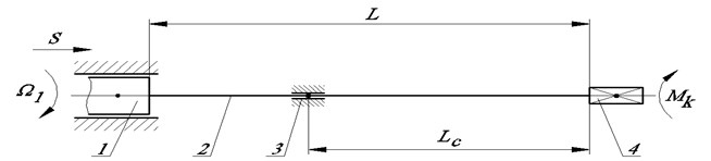
Thus, the mechanical model Fig. 1 will be regarded as a mechanical system, and its motion as a motion of a mechanical system in generalized coordinates. In this case, the tool shank is inserted into the spindle 1 (input member), which performs translational and rotational motion. The instrument itself consists of a rod 2 and a head (output member 4), and the rod passes through an intermediate support 3.
1.2. Development of mathematical model of investigation of dynamic processes of deep holes machining
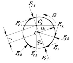
During operation, the following force factors will act on the output link in the longitudinal and cross sections Fig. 2: , – the torque and warping moment; , , – radial, axial and circumferential forces, respectively, 1, 2,..., .
Fig. 2Force factors of the deep hole machining
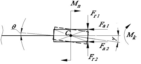
а) Longitudinal section
b) Cross section
For various reasons, the axis of the shank with respect to the axis of the spindle can have an eccentricity of . Due to the curvature of the stem, the axis of rotation of the head may be inclined to the axis of the spindle at an angle . In this case, the center of mass of the head can be displaced relative to the axis of rotation of the spindle by an amount , Fig. 2(b).
Thus, the center of mass of the head relative to the axis of the spindle moves with the velocity , where . At this time on each cutting edge radial , circumferential axial forces operate. These forces are caused by the interaction of the cutting parts with the metal being processed.
The resultant force can cause an additional inclination of the head axis or an additional bending of a the beam under consideration, leading to an additional displacement of the center of mass of the head. In addition, the resultant moment of forces lying in the plane of the drawing in Fig. 1, at each instant leads to an additional rotation of the axis of the head relative to the center of mass by an angle .
The torque from all district forces, each of which is determined and acts according to the cutting conditions, is equal to the sum of the torque moments developed at the cutting edges. Under the action of the torque M, the head is twisted, i.e. the point of the head rotates relative to a certain point on the spindle by an angle . If the one cutting edge, then the torque is determined by the circumferential force at the edge and the friction forces on the support plates [11, 12], i.e.:
In the process of cutting, axial forces arise at the cutting edges, leading to longitudinal elastic movement of the cutting part, which is superimposed on motion due to axial feed, i.e.:
where – resultant force; , – length and cross-sectional area of the rod; – Young’s modulus of the rod material. We introduce the generalized coordinates , , , , and form Lagrange equations of the second kind:
where – kinetic energy of the cutter part; , – generalized coordinate and its derivative; – generalized force.
From the five differential equations the kinetic energy for each generalized coordinate, we obtain the expression for the kinetic energy of the cutting part:
Here – is the mass of the head (cutter part); , – respectively, the moments of inertia of the head relative to its own axis of rotation and relative to the axis passing through the center of mass perpendicular to the plane of the drawing.
Then the system of Lagrange equations of the second kind can be written in the form:
where – resulting acceleration in the direction of the radius vector ; – acceleration of the center of mass of the head, perpendicular to the radius vector .
The generalized forces are found through the ratio of the elementary work to the increment of each generalized coordinate [10, 13], i.e. . In this case, in the total elementary work for each coordinate, we will include work on overcoming the direct resistance, frictional forces and elastic forces. Taking this into account, we obtain a system of differential equations:
Here – resultant force applied to the center of mass along the normal of the radius vector and lying in a plane perpendicular to the axis of rotation; – resultant radial force directed along the radius vector ; – resultant circumferential force; , – radii of the forces and applied to the center of mass of the head; – coefficient of friction proportional to the angular velocity of motion ; – coefficient of elasticity in bending in an arc ; , , , – coefficients of friction proportional to the velocities of motion ,,, ; , , , – coefficients that take into account the elasticity for the generalized coordinates , , , respectively.
To simplify the problem, we consider only torsional and longitudinal oscillations. Let us turn to the third and fourth equations of the system Eq. (6), which describe the force interactions during torsion and longitudinal deformation without bending the rod. We differentiation them with respect to time and divide by the coefficients for the variables , , and replace the force factor by the reaction of the system. Finally, we get:
Here ; , – coefficients equal to , ; (), () – elasticity coefficients, in the general case depend on a certain parameter that is a function of the frequency of disturbing oscillations and the properties of the power main [3]; , – angular velocity of rotation of input and output link; , – initial and final rates of coordinate change; – moment of resistance; – reactive force factor.
After the Taylor series expansion () and the simplifications for , we finally obtain:
From the theory of elasticity, it is known that when torsion of rods, the distortions of the flatness of their cross sections can be neglected [14]. This allows, at least for small oscillations, to allow mutual independence of axial and torsional oscillations. Let’s pass to Laplace representation (). We take into account that ; . We determine under zero initial conditions the transfer function of the effect of the axial vibrations of the technological object on its torsional oscillations for the cases of the matched load [8, 12]:
Fig. 3The oscillation source a) shavings and harmonic oscillations, b) the longitudinal displacement speed ϑ and the rotation frequency Ω of the process object: h – axial movement; φ=ω∆t
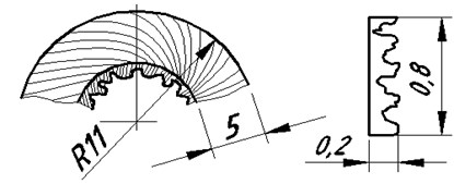
a)
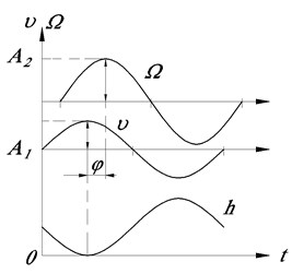
b)
The frequency characteristic describes the variation of the angular velocity with respect to the speed variations of the longitudinal displacement of the cutting part or the lower part of the drill string. The source of such changes is the bit or the interaction of the cutting part of the drill with the part, during which oscillations of different frequency and amplitude can be generated. Their illustration is the chips when deep hole machining with by a gun drill ⌀16.25+0.17 mm in 10GN2MFA steel, Fig. 3(a).
Analysis of breaks on the inner surface resulting from the chipping of metal particles [15] show that at a speed of 1350 rpm and a feed of 0.0346 mm/rev, the oscillation frequency is 7×10³ s-1 (1140 Hz). Therefore, we introduce the correction .
In Fig. 3(b) shows the oscillating process during deep hole machining. Here, the speed of longitudinal displacement of the driven end varies according to the law:
And the rotational speed:
If the phase lag is , then with the maximum speed of axial impact, the speed of rotation of the actuator will be minimal. In addition, if is unchanged, the value of can be greater or less because of the properties of the system. Such features of the process have a significant effect on the performance of the mechanical drive. Obviously, their knowledge is very important, since it makes it possible to determine rational regimes for deep hole machining, milling, drilling for oil and gas. When choosing a rational operating mode, it is also necessary to know the oscillation frequency generated by the actuator and the desired combination of and .
Apparently, it is will be different for different executive device (cutting part of a drill, bit, etc.). Some explanation of the latter circumstance gives an analysis of the operation of the mechanical drive of the cutting part when drilling deep holes [12]. As an example, let us turn to the experiment considered in [7] with the machining of holes ⌀16.25+0,17 mm in 10GN2MFA steel using a gun drill with a diameter of 15.9 mm and a length of 650 mm. The logarithmic frequency characteristics of a gun drill when processing such a hole are shown in Fig. 4.
Fig. 4Logarithmic frequency characteristics of gun drill
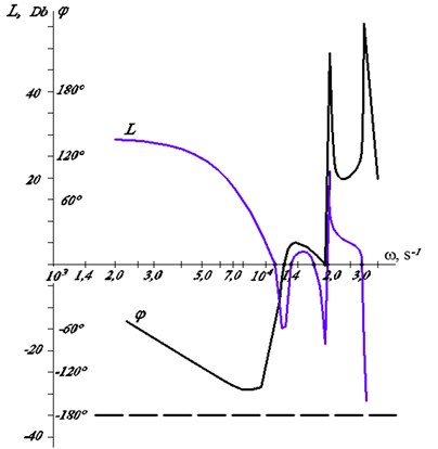
Here it is seen that at a frequency of 7·103 s-1, the amplitude of the oscillation with respect to the oscillations decreases in 10L/20 times in comparison with the low frequencies, and the phase lag is equal 140° (Fig. 4).
Since in the process of cutting or drilling with cone bit there is a regular or close to it an oscillatory perturbation action, then the reaction to it of these drives will be similar. Such a regime ensured the durability of the drill to the first tool refurbishing of 220 min at the required quality of the surface. Since in the process of cutting or drilling with cone bit there is a regular or close to it an oscillatory perturbation action, then the reaction to it of these drives will be similar.
Therefore, on the basis of the conducted study, it can be assumed that for a drill bit with synchronous operation of roller cone, a mode is preferred where, with a certain lifting of the tool, its rotation speed increases.
On the basis of the conducted study, it can be assumed that for bit with synchronous operation of roller cones, a mode is preferred when, with a certain lifting of the tool, its rotation speed increases, and at the moment of impact of the bit on the well bottom, the value of decreases. With this mode, the rotation frequency responds rather poorly to longitudinal oscillations (10 times less than for small ). This corresponds to the following parameters: phase delay –90-180°; amplitude decrease 20 dB ( 10).
2. Conclusions
The foregoing mathematical receptions us to study the variations in the speed of rotation of the cutter part and stresses in the rod (drill pipe) by various lengths, to evaluate the influence of process parameters in rotary boring or in deep hole machining technologies, and also choose rational operating modes and design of the tool.
References
-
Terekhov V. M., Kondratenko L. A., Mironova L. I. Some dynamic features of interaction the cutting part of the gun drill with the detail. Journal of Engineering and Automation Problems, Mechanical Engineering and Automation Problems, Vol. 4, 2016, p. 78-84.
-
Terekhov V. M., Kondratenko L. A. About mathematical model of the process of deephole machining. AS RF. Journal of Machinery Manufacture and Reliability, Vol. 1, 1999, p. 55-61.
-
Kondratenko L. A. Fluctuations in the bit rotation frequency while simultaneous drilling by the rotor and downhole hydraulic machines. Journal of Machine Science, Academy of Sciences of the USSR, Vol. 4, 1987, p. 44-52.
-
Messond Amor, Weis Claus Monitiring a deep holl drilling process bu nonlinear time series modeling. Journal of Sound and Vibration, Vol. 326, Issues 3-5, 2009, p. 620-630.
-
Weinert K., Peters C., Wittkop S. Finite elemente optimieren lange bohrer technika, Vol. 9, 2004, p. 8-12, (in German).
-
Mustafa Gunay, Ulvi Seker Gokhan Sur. Design and construction of a dynamometer to evaluate the influence of cutting tool rake angle on cutting forces. Materials and Design, Vol. 27, 2006, p. 1097-1110.
-
Kondratenko L. A., Terekhov V. M. Numerical investigation of the dynamic properties of gundrill. Journal of Problems of Mechanical Engineering and Reliability of Machines, Vol. 4, 1996, p. 78-82.
-
Kondratenko L. A., Terekhov V. M., Mironova L. I. About one method of research torsional vibrations of the core and his application in technologies of mechanical engineering. Journal of Engineering and Automation Problems, Vol. 1, 2017, p. 133-137.
-
Kondratenko L., Terekhov V., Mironova L. The aspects of roll-forming process dynamics. Vibroengineering Procedia, Vol. 8, 2016, p. 460-465.
-
Yablonsky A. A. Course of Theoretical Mechanics. Part 2. Moscow, High School, 1977.
-
Kondratenko L. A. Vibrations and Speed Regulation Methods of Movement of Technological Objects. Moscow, MRSU, 2005.
-
Kondratenko L. A. Calculation of Movement Speed Variations and Stresses in Machine Assemblies and Components. Moscow, Sputnik, 2008.
-
Sedov L. I. Continuum Mechanics. Vols. 1-2. Moscow, Nedra, 1970.
-
Feodsiev V. I. Strength of Materials. Moscow, FML, 2001.
-
Klushin M. I. Cutting of Metals. Moscow, Mashghiz, 1958.
Cited by
About this article

