Abstract
This paper proposes an inertance calculation method of the ball-screw inerter when considering the nonlinear factors, which will be called as the nonlinear inertance. With the inerter increasingly used in vibration damping systems, the effects that caused by the nonlinear factors, especially by friction, have attracted a lot of attention. The inertance is deemed as the inherent property of the inerter. In most systems, an analysis with the application of the inertance of the ideal linear inerter (which will be called as the ideal linear inertance) may produce a considerable error, thus the consideration of nonlinear factors becomes increasingly significant when calculating the inertance. Based on the Frenet frame theory and Hertz contact theory, the relative sliding speed and sliding friction torque between balls and raceways of the ball-screw inerter have been deduced, thus obtaining the sliding friction efficiency of the balls, and then introducing the rolling friction efficiency of the balls, and finally obtaining the method of the nonlinear inertance calculation after friction consideration. Based on the jobs above, an experimental study on the inertance of ball-screw inerter was carried out. In addition, the ideal linear inertance, nonlinear inertance and experimental value were compared with each other. The results show that the nonlinear inertance is closer to the experimental value; it demonstrates the accuracy of the calculation method proposed in this paper. Besides, the influences of other parameters of the ball-screw mechanism on the inertance are also analyzed, including the nominal radius, lead, contact angle, ball radius and number of balls, the comparative results show that the lead and ball radius have a great influence on the inertance. These results provide a more accurate inertance calculation method for designing a ball-screw inerter and its application in engineering vibration damping systems, meanwhile the theory and approach about inerter will also be developed.
1. Introduction
Inertance, measured in kilograms, is the constant of proportionality of inerter which is a two-terminal mechanical device with the property that the applied force at its two terminals is proportional to the relative acceleration between them [1, 2]. In the past few years, the ideal inerters were applied to vehicle, motorcycle and train suspension systems, where significant performance improvements were achieved [3]. However, with the inerter increasingly used in the vibration damping systems, effects caused by nonlinear factors, especially the friction, attracted a lot of attention. In most systems, carrying on analysis with the application of ideal linear inertance may produce a considerable error, thus the consideration of nonlinear factors becomes increasingly significant when calculating the inertance.
The concept of inerter was first proposed by Smith at 2001 when researching the synthesis of mechanical networks, and two basic forms of inerter were given: ball-screw inerter and rack-pinion inerter [1, 4]. After that, Smith and his team carried out constant researches on inerter and its application. In 2004, the inerter was used by Smith team in vehicle suspension and high-performance motorcycle control systems [5]. In 2005, McLaren Eq. (1) Team won the championship because of the installation of an inerter [2] in the car damping system, which enhanced the grip performance of the car. Starting from 2006, Fu-Cheng Wang has explored the application of inerter on train suspensions and buildings [6-11]. Since 2007, the Jiangsu University team in China verified that the inerter had the characteristics of passing high-frequency and resisting low-frequency. Besides, the ideal ceiling and floor damping of the vehicle suspension are realized by using the inerter. With this achievement, the Jiangsu University team applied for several international PCT patents [12-14]. In 2013, researchers of China North Vehicle Research Institute carried out an application research of inerter and the ISD on the high mobility crawler vehicle [15]. In 2015, Yinglong Hu et al. considered the problems of analysis and optimization of the inerter-based isolators based on an “anti-axial” single-degree-of-freedom isolation system [16].
With deepening the research, the influences of nonlinear factors (including friction, backlash, elastic effects) on the inerter were continually put forward. In 2008, considering that the gaps, friction and elastic forces exist in the inerter structure, Fu-Cheng Wang established the inerter nonlinear mechanic model and studied the influence of these nonlinear factors on the ISD suspension calculation process [17]. In 2009, the Smith team carried out a series of bench tests on a ball-screw inerter and rack-pinion inerter. They found that the backlash and elastic force existing in the mechanical inerter had a direct impact on its mechanical properties [18]. In 2016, a Jiangsu University team established a nonlinear inerter model and carried out mechanical properties tests based on the consideration of the friction, gap and screw elastic force. And finally, they had obtained the mechanical model structure of the inerter which was able to identify parameters [19]. In the same year, they proposed a new type of fluid inerter and analyzed the nonlinearities including friction and nonlinear damping force caused by the viscosity of fluid [20].
However, no one has yet proposed how to calculate the inertance taking into account of the nonlinear factors. The inertance calculation equation of the ideal ball-screw inerter is:
where represents the lead of ball-screw mechanism and s represents the rotary inertia of flywheel. Obviously, it didn’t take nonlinear factors into account. [17-20] show that nonlinear factors have a great influence on the kinetic properties of inerter and damping performance of ISD suspension. With the increasingly use of inerter, inertance, inherent inerter property, its calculating accuracy gets particularly important, especially in low-frequency and precise damping systems. Thus, the inertance calculation method of the inerter, which influenced by nonlinear factors, needed to be further studied in the engineering applications.
The objective of this paper is to study the calculation method of nonlinear inertance of ball-screw inerter, which deduce the differential sliding velocity between the balls and raceways, thus obtaining the sliding friction efficiency of the balls, and finally obtaining the calculation method of the nonlinear inertance. Based on the jobs above, an experimental study on the inertance of ball-screw inerter was carried out. In addition, the ideal linear inertance, nonlinear inertance and experimental value are compared with each other. The results show that the nonlinear inertance is closer to the experimental value, it demonstrates the accuracy of the calculation method proposed in this paper. Besides, the influences of other parameters of the ball-screw mechanism on the inertance are also analyzed, including nominal radius, lead, contact angle, ball radius and number of balls. The organization of this paper is as follows. The assumptions in this paper are described in Section 2. Section 3 deduces the differential sliding velocity between balls and raceways. In Section 4, the sliding friction efficiency is deduced, and the rolling friction efficiency is quoted. Through the previous derivations, the inertance of ball-screw inerter is ultimately obtained in Section 5. In Section 6, the accuracy of the nonlinear inertance calculating method that mentioned in this paper was verified trough experiments, and the influences of some parameters of the ball-screw mechanism on the inerter are analyzed. Conclusions are drawn in Section 7.
2. Ball-screw inerter modal
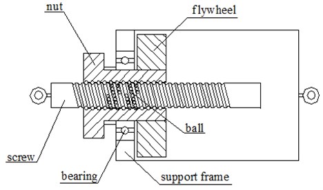
Fig. 1 is a model of ball-screw inerter, including screw, nut, balls, flywheel, bearing and support frame; where the ball-screw mechanism is composed of a screw and ball nut, the nut is permanently connected with the inner bearing ring, and the outer bearing ring is permanently connected with the support frame, the flywheel is permanently connected with the nut in the support frame, a lifting lug is connected with the support frame, and another lifting lug is connected with the screw. The force acts on two lifting lugs, promoting the linear motion of the screw, and making the nut and the flywheel rotate at the same time.
To better deduce the nonlinear inertance of the ball-screw inerter, the following assumptions are made for the ball-screw inerter model shown in Fig. 1:
(1) Assume that the force of every working ball in the raceway is the same;
(2) Assume that two contact angles which between the ball and two raceways are approximately equal;
(3) Assume that the ball-screw mechanism model is fit for the Hertz contact model;
(4) Assume that the truncation error produced by the calculating process of frictional moment between ball and raceway can be negligible.
(5) Assume that the friction coefficient between the balls and raceways is constant.
Fig. 1Model of ball-screw inerter
3. Differential sliding speed of contact point
3.1. Establishment of coordinate system
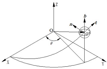
In order to carry out a dynamic analysis on the ball screw assembly in inerter, a World Coordinate System (-) is established as shown in Fig. 2, in which the axis coincides with the central axis of the screw; Moreover, a Frenet frame is established based on the motion curve of the ball center to study the sliding phenomenon of the contact area between balls and raceway.
Fig. 2Establishment of coordinate system
Set the base vector of the World Coordinate System as:
And the base vector of the Frenet frame as:
where the basic vector of the Frenet frame can be expressed as [21]:
The curve equation of the ball center in the World Coordinate System can be expressed as:
where represents the nominal radius of ball screw assembly, represents ball center track which is relative to the World Coordinate System turning angle, represents spiral angle of the ball screw assembly.
To figure out the ratio between World Coordinate System and Frenet frame, take the derivative of Eq. (6) to obtain:
Substitute Eqs. (6)-(8) into Eq. (3)-(5) and get:
where define:
According to Eq. (9) and (10), one can know that:
And then by performing the matrix inverse of Eq. (10), one can obtain:
3.2. Contact point movement on ball
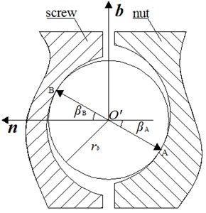
As shown in Fig. 3, in the Frenet frame, can be defined as the contact point between the ball and the nut, while as the contact angle, and can be defined as the contact point between the ball and screw, while as the contact angle.
Fig. 3Schematic of contact point between ball and raceway
Transforming Eq. (7) into the Frenet frame:
Assume that the instantaneous rotation angular velocity of the ball in the Frenet frame is as: then the instantaneous velocity of contact point and can be denoted as:
In the two equations above, represents the ball radius, , .
3.3. Contact point movement on nut side
According to the drive principle of ball-screw mechanism, when the displacement of screw is , the nut rotation angular displacement will be , where represents the screw lead. So, when the velocity of screw is , the angular nut velocity can be written as:
Then transform it into the Frenet frame:
Therefore, the velocity of contact point on the screw can be denoted as:
3.4. Contact point movement of on screw side
The velocity of contact point in the World Coordinate System can be denoted as:
Transform the Eq. (17) into the Frenet frame:
3.5. Relative sliding speed of contact point
For contact point , according to the velocity on the screw and the velocity on the nut side, the relative sliding speed of contact can be obtained as:
Similarly, the relative sliding speed of contact can be obtained as:
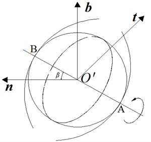
As shown in the Fig. 4 above, due to the existence of contact angle in the ball-screw mechanism, while the ball rolls along the curve of the ball center, a spin-slip phenomenon around the common normal of contact point will also simultaneously exist.
The inerter is commonly used in the low and medium frequency workplaces, and the common normal of contact point and are both inside the normal plane , so it can be approximately deemed as . And according to the Plane Vector Geometry: , it means the common normal of two contact points are duplicated. Assume the angular velocity when the ball is rotating around common normal as , and then obtain the following equation set:
Fig. 4Schematic of ball movement
Substitute the equation set Eq. (21) into the expression of and , and then convert it into angular velocity rotating around common normal:
4. Friction efficiency
4.1. Interface stress
As shown in Fig. 5, according to the Hertz contact theory, the shape of the contact surface between the ball, nut, and screw is ellipse. Assume that the major semi-axis of ellipse between the ball and nut is as , and the minor semi-axis of ellipse is as . Then, create a Cartesian coordinate system (-) by taking the ellipse center as its origin, where coincides with the major axis of the ellipse, coincides with the minor axis, and is perpendicular to the - plane; Similarly, the major semi-axis of the ellipse between the ball and screw is assumed as , and the minor semi-axis is assumed as . Then, create a Cartesian coordinate system (-) by taking the ellipse center as its origin , where coincides with the major axis of the ellipse, coincides with the minor axis, and is perpendicular to the - plane. Due to space limitation, the calculating methods of major semi-axis and , minor semi-axis and can be referred to the methods in literature [22].
Fig. 5Schematic of contact area between ball and raceway
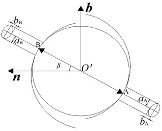
Fig. 6Schematic of contact stress distribution
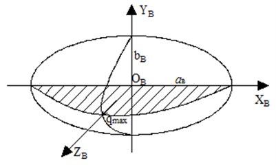
As shown in Fig. 6, take the contact area between the ball and screw as an example, inside the ellipse contact area, the contact stress of every point is different. On axis , due to the maximum deformation, its contact stress reaches the maximum value too. The contact stresses of other points are distributed according to the half ellipsoid rule, and these values are [22]:
where, represents the stress of random point inside the ellipse contact area, represents the maximum stress inside the ellipse contact area.
The stress of the ellipse contact area is distributed according to the half ellipsoid rule, so the positive pressure acting on a single working ball, and the stress of every point has an integral ratio as follows [22]:
where, represents the elliptical contact area.
The Eq. (24) shows that in order to get the stress of random point inside the ellipse contact area, the maximum stress inside it has to be calculated first. The following shows the solution of maximum stress .
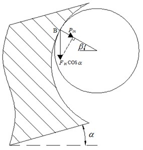
As shown in Fig. 7, due to the existence of lead angle , the axial excitation load acting on the single working ball is , so the positive pressure acts on a single working ball can be obtained as:
where represents the ball number in the ball-screw mechanism;
Synthesize Eq. (25) and Eq. (26), the maximum stress inside the ellipse contact area:
Fig. 7Schematic of stress analysis
4.2. Friction torque of contact area
As shown in Fig. 9, take the contact between the screw and ball as an example, take a random point in the coordinate system, and its area element , then its friction can be obtained as , where refers to the friction coefficient of contact area, and refers to the positive pressure of point , continue to get its moment of the area relating to axis as based on the length between and .
Fig. 9Schematic of contact surfaces infinitesimal
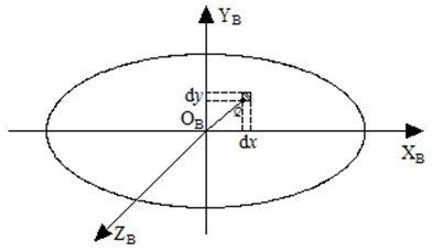
Thus, the moment of the whole area relating to axis :
Decompose to the three-coordinate axis of Frenet frame:
where represents the friction torque of contact point in the Frenet frame.
4.3. Sliding friction efficiency
The angular velocity and friction moment of two contact points and in the Frenet frame have been obtained above, so the its friction power is respectively shown as bellow:
where represents the friction moment of contact point in the Frenet frame;
The sliding friction power of single ball is a sum of two equations above:
Since the physical quantity power is a scalar, its value will not change along with the change of coordinate system, thus the excitation power while in the Frenet frame can be expressed as:
Define the energy consumption of rolling friction that account for the percentages of excitation as sliding friction efficiency:
4.4. Rolling friction efficiency
Define the energy consumption of rolling friction that account for the percentages of excitation as rolling friction efficiency [23]:
where represents the rolling friction coefficient, generally within the range of 0.0036-0.0038.
5. Nonlinear inertance
If this research does not take the consideration of nonlinear factors, according to the literature [1], the calculation approach of ideal linear inertance of the ball-screw inerter can be expressed as:
To reduce the inertance calculation error of ball-screw inerter in the engineering damping system, based on the friction efficiency derived above, including the sliding friction efficiency and rolling friction efficiency. Introduce the nonlinear factors on the basis of ideal linear inertance of the ball-screw inerter, and finally the nonlinear inertance calculation method can be deduced in this paper, which is:
6. Experimental verification of nonlinear inertance and parameter evaluation
6.1. Experimental verification
To verify the derived nonlinear inertance and the accuracy of this calculation method, this research has performed a testing experiment to the inertance of the ball-screw inerter on the ES-10-240 vibration test bench, the parameters of ball-screw mechanism are shown in Table 1 and the setup of vibration test bench is shown in Fig. 10. This experiment has also installed a force sensor at the connection between the ball-screw inerter and the vibration test bench, and installed several vibration acceleration sensors on the vibration table at the same time, and then the DASP V10 model analyzer was used for simultaneous vibration data acquisition and signal spectrum analysis, by loading different frequencies of square wave excitation to the ball screw inerter, which are within the frequency range from 1 Hz to 12 Hz, for every rises of 1 Hz per test, and the experimental results of force and acceleration are recorded in Table 2.
Table 1Independent geometric parameters of ball-screw mechanism
Name | Scale |
Nominal diameter () | 6 mm |
Screw lead () | 10 mm |
Contact angle () | 45° |
Ball diameter () | 3 mm |
Ball number () | 18 |
Fig. 10Experimental device and its live photos
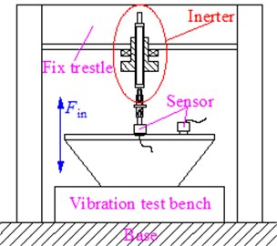
a) Experimental device
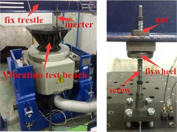
b) Living photos
Table 2Experimental test force and acceleration
Frequency (Hz) | Force (N) | Acceleration | Frequency (Hz) | Force (N) | Acceleration |
1 | 6.64 | 0.18 | 7 | 105.47 | 2.56 |
2 | 9.92 | 0.26 | 8 | 130.49 | 3.29 |
3 | 16.79 | 0.42 | 9 | 168.41 | 4.12 |
4 | 35.65 | 0.90 | 10 | 208.03 | 5.21 |
5 | 54.41 | 1.35 | 11 | 248.80 | 6.25 |
6 | 79.09 | 1.94 | 12 | 308.17 | 7.69 |
Table 2 is organized into Fig. 11, with the frequency rises, both ends of the force and acceleration have the increasing trend, according to the definition of inertance: , where is the force of two ends, is the acceleration of two ends, the experimental results of inertance can be obtained, as shown in Table 3.
Table 3Experimental results of inertance
Frequency (Hz) | Experiment-b (kg) | Frequency (Hz) | Experiment-b (kg) |
1 | 37.6 | 7 | 41.2 |
2 | 38.1 | 8 | 39.7 |
3 | 39.6 | 9 | 40.9 |
4 | 39.4 | 10 | 39.9 |
5 | 40.3 | 11 | 39.8 |
6 | 40.8 | 12 | 40.1 |
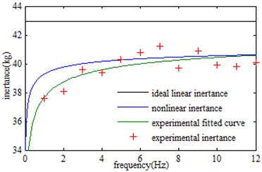
After that, fit the test points by using MTALAB cftool tool box. In addition, the experimental fitting curve is compared with the nonlinear inertance and the ideal linear inertance, thus obtaining the following graph Fig. 12.
These experimental results show that the nonlinear inertance derived by this paper is slightly larger than the experimental fitting results. When the frequency is less than 12 Hz, the error between the ideal linear inertance and the experimental inertance is greater than 10.0 %. It can be known that the ideal linear inertance is not accurate enough in a low frequency range of the ball-screw inerter, in some demanding vibration isolation systems; the use of the ideal linear inertance will introduce large errors. However, when the frequency is less than 12 Hz, the error between the nonlinear inertance and the experimental inertance is less than 5.0 %, especially when the frequency is greater than 3 Hz, the error between the nonlinear inertertace and experimental inertance is less than 2.0 %. Obviously, compare with the ideal linear inertance of the ball-screw inerter, the nonlinear inertance derived in this paper is more accurate in the low frequency range of the inerter.
Fig. 11Experimental test force and acceleration
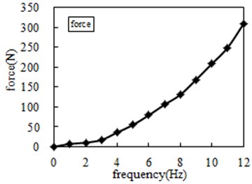
a) Force
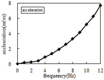
b) Acceleration
Fig. 12Inertance obtained by different methods
6.2. Parameter evaluation
Fig. 13 shows the comparison of the influence of different lead on the nonlinear inertance, the other parameters are shown in Table 1. At the same frequency, the smaller is the lead, the greater is the inertance, the stronger is the nonlinearity of inertance of the ball-screw inerter. Additionally, as the frequency increases, the nonlinear inertance tends to be stable.
Fig. 13Influence of different lead on inertance
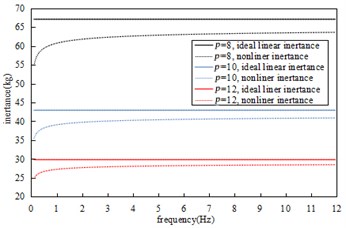
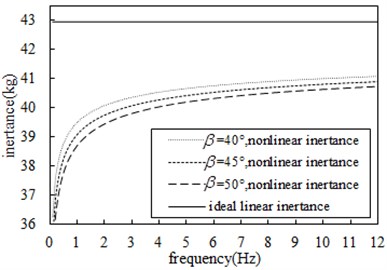
Fig. 14-Fig. 17 show the comparison of the effects of nominal radius, ball radius, ball number, and contact angle on the nonlinear inertance respectively, the other parameters are shown in Table 1. At the same frequency, the larger is the nominal screw radius, the smaller is the ball radius, the larger is the number of balls and the larger is the contact angle, so the nonlinear inertance will be smaller, and the nonlinearity of the inertance will be stronger. In addition, within 3 Hz, the frequency has a great influence on the nonlinearity of inertance, the smaller is the frequency, the stronger will be the nonlinearity of inertance and the smaller will be the inertance; As the frequency increases, the nonlinear influence of the frequency on the inertance is weakened, and the inertance tends to be stable.
Fig. 14Comparison of influence of different nominal radius on inertance
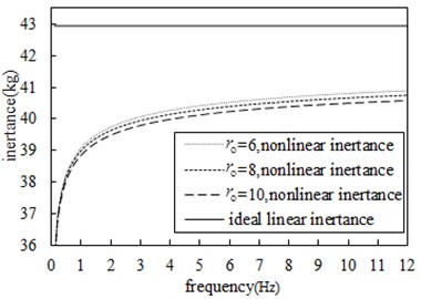
Fig. 15Comparison of influence of different ball radius on inertance
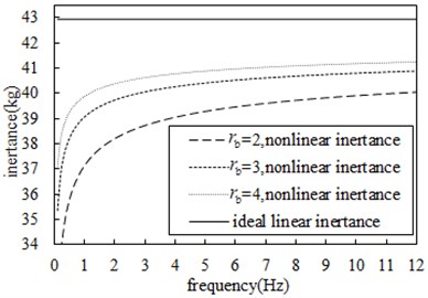
Fig. 16Comparison of influence of different ball numbers on inertance
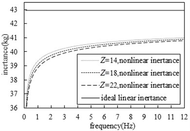
Fig. 17Comparison of influence of different contact angles on inertance
This paper only considers the influence of the parameters of the ball-screw mechanism in the inerter, and the coupling between the friction coefficient and the friction torque is not taken into account. [24] shows that the change in friction torque will change the viscous resistance of the lubrication medium to which the ball is subjected, which will result in a different friction coefficient. With the increase of the frequency, the difference in the friction coefficient will result in the nonlinear inertance close to the ideal linear inertance in a fluctuating shape.
7. Conclusions
With the Frenet frame theory and Hertz contact theory, this paper has validated the calculation method accuracy of the nonlinear inertance based on the proper simplification of ball-screw inerter model and some experiments. In addition, the parameters of the ball-screw mechanism have some influences on the non-linear inertance too. Some conclusions are summarized as follows:
1) At low frequencies especially below 3 Hz, the error between the ideal linear inertance and the actual inertance of the ball-screw inerter is greater than 10 %. In some demanding vibration isolation systems, the use of ideal linear inertance will produce a large error.
2) The error of the nonlinear inertance of ball-screw inerter deduced in this paper is less than 5 % at low frequencies compared with the actual inertance, especially when the frequency is larger than 3 Hz, its error is less than 2 %. Therefore, the inertance of ball-screw inerter deduced in this paper is relatively accurate.
3) The smaller is the ball-screw inerter lead, the greater is the inertance, and the stronger is the nonlinearity of inertance. In addition, at the same frequency, the larger is the nominal radius of the screw, the smaller is the ball radius, the larger is the number of balls and the larger is the contact angle, so the nonlinear inertance will be smaller, and the nonlinearity of the inertance will be stronger.
4) Within 3 Hz, the frequency has a great influence on the nonlinearity of inertance, the smaller is the frequency, the stronger will be the nonlinearity of inertance, and the smaller will be the inertance; As the frequency increases, the nonlinear influence of the frequency on the inertance is weakened, and the inertance tends to be stable.
References
-
Smith M. C. Synthesis of mechanical networks: inerter. IEEE Transactions on Automatic Control, Vol. 47, Issue 10, 2002, p. 1648-1662.
-
Chen M. Z. Q., Papageorgiou C., Scheibe F., Wang F.-C., Smith M. C. The missing mechanical circuit element. IEEE Circuits and Systems, Vol. 9, Issue 1, 2009, p. 10-26.
-
Wang Fu-Cheng, Su Wei-Jiun Impact of inerter nonlinearities on vehicle suspension control. Vehicle System Dynamics, Vol. 46, Issue 7, 2008, p. 575-595.
-
Smith M. C. Force-Controlling Mechanical Device. UK PCT/GB02/03056.2003.01.06.
-
Smith M. C., Wang F. C. Performance benefits in passive vehicle suspensions employing inerters. Vehicle System Dynamics, Vol. 42, Issue 4, 2004, p. 235-257.
-
Wang F. C., Yu C. H., Chang M. L., et al. The performance improvements of train suspension systems with inerters. Proceedings of the 45th IEEE Conference on Decision and Control, CA, US, 2006, p. 1472-1477.
-
Wang F. C., Liao M. K., Liao B. H., et al. The performance improvements of train suspension systems with mechanical networks. Vehicle System Dynamics, Vol. 47, Issue 7, 2009, p. 805-830.
-
Wang F. C., Liao M. K. The lateral stability of train suspension systems employing inerters. Vehicle System Dynamics, Vol. 48, Issue 5, 2010, p. 619-643.
-
Wang F. C., Hsieh M. R., Chen H. J. Stability and performance analysis of a full-train system with inerters. Vehicle System Dynamics, Vol. 50, Issue 4, 2012, p. 545-571.
-
Wang F. C., Chen C. W., Liao M. K., et al. Performance analyses of building suspension control with inerters. Proceedings of the 46th IEEE Conference on Decision and Control. New Orleans, Louisiana, US, 2007, p. 3786-3791.
-
Wang F. C., Hong M. F., Chen C. W. Building suspension with inerters. Proceedings of the Institution of Mechanical Engineers, Part C: Journal of Mechanical Engineering Science, Vol. 224, Issue 8, 2010, p. 1605-1616.
-
Chen Long, Zhang Xiao-Liang, Wang Ruo-Chen Vehicle Suspension with Inertial Accumulator. China, ZL200810123830.8, 2008-12-24, (in Chinese).
-
Chen Long, Zhang Xiao-Liang, Nie Jia-Mei, et al. A Passive Skyhook and Groundhook Damping Vibration Isolation System. China, 102494071A. 2013-12-11, (in Chinese).
-
Shen Yujie, Chen Long, Yang Xiaofeng, Shi Dehua, Yang Jun Improved design of dynamic vibration absorber by using the inerter and its application in vehicle suspension. Journal of Sound and Vibration, Vol. 361, 2016, p. 148-158.
-
Du Fu, Mao Ming, Chen Yi-Jie, et al. Structure design and performance analysis of Inerter-spring-damper suspension based on dynamic model and parameter optimization. Journal of Virbration and Shock, Vol. 33, Issue 6, 2014, p. 59-65, (in Chinese).
-
Yin Long Hu, Michael Chen Z. Q., Zhang Shu, Li Xu Huang Analysis and optimisation for inerter-based isolators via fixed-pointed theory and algebraic solution. Journal of sound and vibration, Vol. 346, 2015, p. 17-36.
-
Wang F.-C., Su W.-J. Impact of inerter nonlinearities on vehicle suspension control. International Journal of Vehicle Mechanics and Mobility, Vol. 46, 2008, p. 575-595.
-
Papageorgiou C., Houghton N. E., Smith M. C. Experimental testing and analysis of inerter devices. Journal of Dynamic Systems, Measurement and Control, Vol. 131, Issue 1, 2009, p. 1-11.
-
Sun X. Q., Chen L., Wang S. H., Zhang X. L., Yang X. F. Performance investigation of vehicle suspension system with nonlinear ball-screw inerter. International Journal of Automotive Technology, Vol. 17, Issue 3, 2016, p. 399-408.
-
Shen Yujie, Chen Long, Liu Yanling, Zhang Xiaoliang Modeling and optimization of vehicle suspension employing a nonlinear fluid inerter. Shock and Vibration, 2016.
-
Samad M. D., Iftekharuddin K. M. Frenet frame-based generalized space curve representation for pose-invariant classification and recognition of 3-D face. Human-Machine Systems, IEEE Transactions, 2016, p. 1-12.
-
Miyaguchi K., Ninomiya M., Watanabe Y., et al. A study on the friction torque variation of a ball screw at motion direction change: friction torque variation due to the change in ball contact points. Journal of Japan Society for Precision Engineering, Vol. 68, Issue 6, 2002, p. 833-837.
-
Lin M. C., Velinsky S. A., Ravani B. Design of the ball screw mechanism for optimal efficiency. Journal of Mechanical Design, Vol. 116, Issue 3, 1994, p. 856-861.
-
Chen Yongjiang, Tang Wencheng Theoretical and experimental research on friction torque model of micro-type ball screw. Journal of Southeast University (Natural Science Edition), Vol. 41, Issue 6, 2011, p. 982-986, (in Chinese).
About this article

Wen’s main task is to put forward the main idea of the article, research the project and guide the article writing. Guo research the project and write article based on research results. Li and Liu modify the article according to the results of the study. Goh’s main task is to polish the article.
