Abstract
Based on the D’Alembert principle and the hypothesis of Euler-Bernoulli beam, the vehicle-bridge coupling vibration equations of vehicle bump test were established using mode decomposition method. As bump test applies an impact pulse excitation to bridge structure, the initial conditions to calculate the system vibration equations were derived using momentum conservation law. Then the system vibration equations were solved by using Runge-Kutta method and the dynamic response of bridge was obtained through mode decomposition method. By comparing the maximum bending moment of each section at h height with the design bending moment of bridge, the limit height in bump test was determined. Finally, a simply supported hollow slab bridge was taken as an example, and the dynamic response of this bridge was calculated to determine the limit bump height in dynamic test. The correctness and effectiveness of this method was validated.
1. Introduction
The excitation methods of bridge dynamic test include self-vibration method, forced vibration method, pulsation method, etc. Vehicle bump test is the most commonly used in self-vibration method for short to medium span bridge [1-3]. The researchers have conducted lots of useful exploratory works in the field of vehicle test with obstacles. Huang et al. let the rear wheels of the truck fall down from the concrete block of 20 cm height at the deck to generate the impulsive force in dynamic test [4]. Kwasniewski et al. placed a wooden plank across the deck to simulate major deterioration of the deck surface [5]. Racanel artificially produced an obstacle at the deck in order to induce an impulse at the superstructure level in the dynamic loading of bridge [6]. Cantieni performed dynamic load test on the undisturbed pavement which placed a thick plank on the roadway [7]. The excitation imposed to bridges by vehicle test with obstacles is forced excitation, whose purpose is to obtain the impact factor of the bridge. However, the so called vehicle bump test of Chinese code suggests that the front wheels stay at bridge in static and the rear wheels fall from the obstacle of height. Then vehicle-bridge coupling system starts to free-decay vibration under impact loads which generated by the process of vehicle bump to bridge structure. Through analyzing free-decay response to obtain the free vibration characteristics (natural frequency, damping ratio, modal shape, etc.) of bridge structure. Thus, the limit bump height for the vehicle bump test is the key to obtain more obvious signal-to-noise ratio of dynamic response and not to cause damage for bridge. Literature [8] suggests that the height of vehicle bump is 5-15 cm. Literature [9] regulates that the height is 15 cm in the case of a single vehicle which is close to the standard load heavy vehicle is adopted as the bump excitation. However, the theoretical basis of the height specified is not given. Therefore, it is necessary to establish a theoretical calculation model of vehicle bump height and determine it accurately.
2. Vibration equations of vehicle-bridge coupling after the vehicle falling down
The process of vehicle falling down is shown in Fig. 1(a). Let the rear wheels of vehicle suddenly fall from the vehicle bump device without horizontal velocity and the vehicle remains stationary level after it falling down. The impulse effect is applied to bridge by utilizing the momentum generated during the falling process of vehicle’s rear wheels.
Fig. 1The vehicle-bridge coupling model of vehicle bumping process
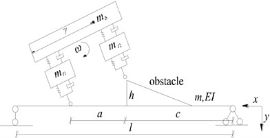
a) The half-car planar and bridge model in the process of falling
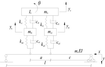
b) The half-car planar and bridge model after the contact with bridge
In this study, a half-car planar model with four degrees of freedom is adopted.
When the rear wheels of vehicle fallen to the deck, the whole mechanical analysis of vehicle can be performed according to Fig. 1(b). The force of vehicle acts on bridge fall into two parts of static and dynamic force. Let and be the dynamic load and static load of front wheel respectively, and be those of rear wheel:
As shown in Fig. 1(b), the equation of motion for bridge structure can be established based on D’Alembert principle and the hypothesis of Euler-Bernoulli beam when the excitation of vehicle is exerted on bridge:
where and are Dirac’s functions.
The dynamic deflection can be set according to mode decomposition method as follows:
where is the th order vibration mode function of simply supported bridge and is the corresponding general coordinate.
Combining Eqs. (2-3) with the orthogonal property of mode shape can obtain:
where ; is the th natural frequency of bridge. Let , then Eq. (4) can be expressed by:
Equations of motion for wheel masses and :
Equations of motion for sprung mass :
where and are dynamic deflections at positions of front and rear wheel for bridge.
Eq. (2) and Eqs. (5-7) can be expressed as the generalized motion equation in matrix form:
where:
3. Solution of vibration equations and determination of bump height
According to conservation of energy, the potential energy of vehicle at the highest point of vehicle bump device is equal to kinetic energy at the moment of vehicle fallen to the deck. Let be the rotation angular velocity of vehicle body at the moment of rear wheel falling to the deck:
Let be the distance between front wheel and mass center of particle system composed of and , it has:
The total momentum of vehicle before the contact of vehicle and bridge can be written:
Let be the momentum of bridge at the moment of contact of vehicle and bridge. Assuming that the momentum along the beam length is evenly distributed, it has:
Differentiating both sides of Eq. (12) with respect to yields:
Substituting Eq. (3) into Eq. (13) at the time with the orthogonal property of mode shape can obtain:
Let , then Eq. (14) can be expressed by:
According to momentum conservation law, it has:
Combining Eqs. (6-7) and Eqs. (11, 15, 16), the initial velocities of all degrees of freedom in can be obtained and all the initial conditions required to solve the theoretical calculation model are determined. Then the values of of each moment can be calculated by using fourth-order Runge-Kutta method. Consequently, the time-history curve of dynamic displacement of bridge can be obtained according to mode decomposition method.
The moment value of each section of certain moment can be expressed as:
Assuming that the design bending moment of each section of bridge is , if the following equation is satisfied, can be considered as limit bump height:
4. Numerical simulation
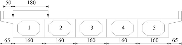
A simply supported hollow slab bridge with uniform section and 20 m span is used for the following numerical simulations and the bridge is composed of 5 slabs. The general layout and the lateral position of vehicle bump are shown in Fig. 2. The cross section of simply supported bridge is shown in Fig. 3. The geometrical and material parameters of vehicle and bridge are listed in Table 1.
Fig. 2The general layout and the lateral position of vehicle bump (unit: cm)
The maximum bending moment of mid-span in 1# slab at the bump height of 0, 5, 10, 15, 20 cm are calculated respectively and the calculation results are shown in Fig. 4. When the bump height of vehicle is 20 cm, the maximum bending moment of mid-span in 1# slab has reached the designed value of bending moment 1580.8 kN·m through analysis. Then it can be considered that the limit bump height of simply supported bridge is 20 cm in the case of vehicle and bump position given in this paper. Fig. 5 provides the displacement response of mid-span. Fig. 6 gives the displacement of each point in 1# slab at the moment of maximum displacement in mid-span. Fig. 7 shows that the bending moment of each point in 1# slab is at the moment of maximum bending moment in mid-span.
Fig. 3The cross section of simply supported bridge (unit: cm)
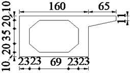
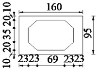
Table 1The calculation parameters of vehicle and bridge
Vehicle parameters | Bridge parameters | ||
, / kg | 4330 | / m | 20 |
/ kg | 3.85×10⁴ | / m | 4.2 |
/ (kg∙m2) | 2.446×10⁵ | / m | 10 |
, / (N∙m-1) | 4.28×10⁵ | Concrete / (kg∙m-3) | 2500 |
, / (N∙m-1) | 2.535×10⁵ | / Pa | 3.25×10¹⁰ |
, / (kg∙s-1) | 0.98×10⁴ | 0.265 | |
, / (kg∙s-1) | 1.96×10⁴ | 10 % | |
Fig. 4The relationship between bump height and bending moment of mid-span in 1# slab
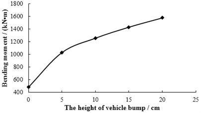
Fig. 5The displacement response of mid-span in 1# slab
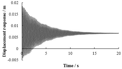
Fig. 6The displacement of each point in 1# slab at the moment of maximum displacement in mid-span
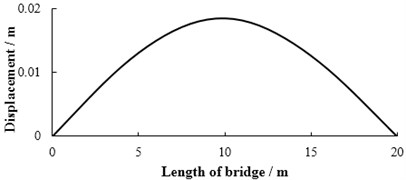
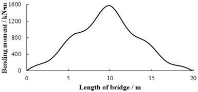
Fig. 7The bending moment of each point in 1# slab at the moment of maximum bending moment in mid-span
5. Conclusions
1) The theoretical research on the height of vehicle bump is carried out, and the feasible and effective theoretical calculation model and determination method are given, which provides a theoretical upper limit value for the selection of vehicle bump height.
2) When the theoretical limit height of vehicle bump is determined, a higher bump height can be used to obtain a higher signal-to-noise ratio of dynamic response and improve the measurement accuracy without causing damage to the bridge.
References
-
Farrar C. R., Duffey T. A., Cornwell P. J., et al. Excitation Methods for Bridge Structures. Office of Scientific and Technical Information Technical Reports, 1999.
-
Peng D. W., Hong J. X., Guo A. M., et al. Dynamic analysis and field-test of jointless bridge. Earthquake Engineering and Engineering Vibration, Vol. 25, Issue 2, 2005, p. 72-76.
-
Zhang J. P. Bridge Detection and Maintenance and Reinforcement. Second Edition, China Communications Press, Beijing, 2011, (in Chinese).
-
Huang C. S., Yang Y. B., Lu L. Y., et al. Dynamic testing and system identification of a multi-span highway bridge. Earthquake Engineering and Structural Dynamics, Vol. 28, Issue 8, 1999, p. 857-878.
-
Kwasniewski L., Li H., Wekezer J., et al. Finite element analysis of vehicle-bridge interaction. Finite Elements in Analysis and Design, Vol. 42, Issue 2, 2006, p. 950-959.
-
Racanel I. R. Static and dynamic testing of a concrete bridge in Bucharest. International Multidisciplinary Scientific Geoconference, 2011.
-
Cantieni R. Dynamic Load Testing of Highway Bridge. Transportation Research Record, 1984.
-
Test Method for Long Span Concrete Bridges (Final Recommendations). Industry Standards of Ministry of Transport, 2013, (in Chinese).
-
Specification for Inspection and Evaluation of Load-Bearing Capacity of Highway Bridges. Highway Science Institution of the Ministry of Transportation, 2011, (in Chinese).
About this article
This work was funded by the National Natural Science Foundation of China (Grant Number 51478203), Training Program for Outstanding Young Teachers of Jilin University.
