Abstract
Study on orchard working vehicle rollover and tipping prediction is important to maintain vehicle stability control in complicated operation conditions of orchard. Existing rollover and tipping prediction models for vehicles can not directly apply to orchard working vehicle, which structure and loading are changing under operation. So it is necessary to move ahead study on orchard vehicle bodywork posture prediction and rollover and tipping prediction by theoretical analysis, mathematical modelling, real vehicle test and other methods. In this paper, firstly, we establish orchard working vehicle dynamic model, analyses variation of key parameters during vehicle instability state, and look for characteristic parameters of vehicle instability. Secondly, active safety control algorithm which based on posture detection of vehicle body is researched. Finally, control model is verified and optimized by scaled test.
1. Introduction
Orchard vehicle, as a typical agricultural and versatile machine, has a lot of different tasks to carry out, such as seeding, spraying, fertilization, pruning and harvesting, etc. As the orchard vehicle often worked on sloping or uneven ground, and the center of mass is raised by lift platform, orchard vehicle rollovers cause over 45 % of fatalities in agricultural accidents each year [1]. The stability loss on rough ground is mainly because wheels follow bumps and hollows of rough ground and cause the instable of the vehicle [2]. So, it is very useful to design a control method which is able to keep orchard vehicle stable in various situations.
Nowadays, rollover protective structure (ROPS) is very popular in protecting the driver from rollover accidents [3-5]. Thambiratnam [6] researched on the performance of bulldozer rollover protective structure, and did a lot of work to solve the contradictory between ROPS bearing requirements and energy absorption requirements. Clark [7] extracted ROPS energy absorbing components for dynamic simulation analysis; he installed a thin cone tube as the energy absorption component on every side of ROPS to improve the energy absorption capacity. In order to study the behaviour of the ROPS mechanism in dynamic and static loading, Clark [8] also use finite element technology to simulate the nonlinear response of agricultural vehicles ROPS which is under the lateral concentrated static load.
But orchard vehicle has to be move freely between canopies of trees; it is impractical to be equipped with a ROPS. To provide necessary protection to drivers working in such a confined and complex environment, researchers should develop an active safety control method [9-12].
The goal of this paper is to design an active safety control method for typical orchard vehicle, which can suitable for its rough and changeable working environment. The experiment of control system, sloped surface and obstacles are carried out and the feasibility of control algorithmic verified.
2. Vehicle model
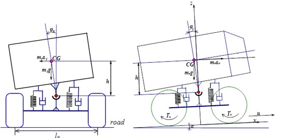
Ignoring the influence of non-sprung mass and lateral wind, considering the nonlinear factors such as front steering angle and the coupling of vertical movement and lateral movement when braking [13-16], 5 degree of freedom orchard vehicle rollover dynamics model has been set up which is shown in Fig. 1.
The dynamics differential equations ca n be got from Fig. 1 as following:
Longitudinal motion equation:
Lateral movement equation:
Yaw motion equation:
Roll motion equation:
Pitch motion equation:
where, is mass of orchard vehicle, is vehicle sprung mass, , are vehicle acceleration along the direction of the and , is yaw velocity, is roll angle, is pitch angle, , are respectively distance from center of mass to epipodium and back shaft, , are vehicle inertia around axis and axis, is steering angle of front wheel; , are vehicle roll length and height of the center of gravity, is suspension equivalent roll stiffness, is suspension equivalent pitch stiffness, is suspension equivalent roll damping, is suspension equivalent pitch damping, is vehicle width, , (1,…, 4) is braking force and lateral force for each tire.
Fig. 1Five-DOF model of orchard vehicle rollover and tip-over
3. Orchard vehicle bodywork posture control algorithm
Three axis accelerometer and gyro scope module of active safety control system (will describe in following section), which is installed in the orchard vehicle centroid, is used to obtain current axis angle and angular velocity , axis angle and angular velocity .
By processing and analysing points sampling data, orchard vehicle ratio coefficient matrix of axis and axis, and , can be determined. is restoring force coefficient of axis direction and is damping coefficient of axis direction. is restoring force coefficient of the axis direction and is damping coefficient of axis direction.
After that, obtain -point estimating value matrixes of angle and angular velocity of and axes and with points sampling data. is estimated value of angle axis at sample time , is estimated value of the angular velocity of axis of points, is -point estimated value of angle axis, is -point estimated value of the angular velocity of axis.
Then, using apriori estimate covariance matrix on axis and axis and , and measurement variance matrix of orchard vehicle posture control system , to calculate -point estimation gain matrix and :
where, is -point estimates of gain of axis angle, is -point estimates of gain of axis angle angular velocity, , , is -point estimates of gain of axis angle, is -point estimates of gain of axis angle angular velocity.
Obtain measurement results matrix with the measurement results of orchard vehicle posture control system. is -point dip direction of axis, is -point angular velocity of axis, is -point dip direction of axis, is -point angular velocity of axis.
Solve -point estimated value matrix of angle and angular velocity and :
Calculate apriori estimate covariance matrix at -point and to facilitate the subsequent iteration:
At last, get -point orchard vehicle output acceleration control results and angle of rotation in the moment. The flow chart of control algorithm is shown in Fig. 2:
4. Experiment results and analysis
A full-sized vehicle is difficult to operate and involves significant safety issues in unstable driven application which involves vehicle rollover and tip-over. It is more convenient to use a 1:8 scaled vehicle to test active safety control algorithm, which is mentioned in previous section. The developed control algorithm will be validated with the scaled vehicle since lateral and vertical dynamics of it are similar to those of a full-sized vehicle.
Fig. 2Flow chart of bodywork posture control algorithm
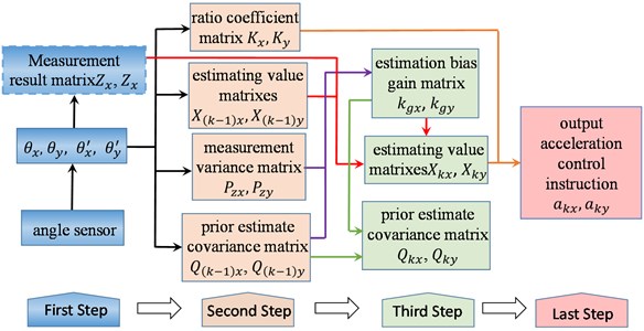
Fig. 3Main structure of experimental system
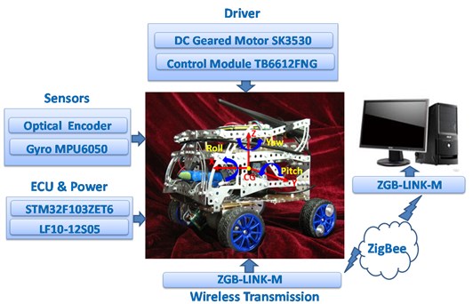
A microcontroller (STM32F103ZET6) from STM microelectronics is used for real-time data acquisition and control of the scaled vehicle speed and steering. The microcontroller is installed on the test vehicle. It samples the data from sensors and wirelessly sends them to a ZigBee receiver connected to a computer. MPU6050 from STMicroelectronics, which combines a 3-axis gyroscope, 3-axis accelerometer and a Digital Motion ProcessorTM (DMP), are used to measure acceleration and angle rate, respectively. It is placed near the C.G. of the vehicle, to measure the yaw, roll, pitch angle and rate. The front wheel of vehicle is driven by DC geared motor (SK3530). Microcontroller send control signal to drive motor control module (TB6612FNG). The speed of front wheel (which include right and left side) is measured by E6A2-CS3C speed encoder from OMRON. The photographs of the microcontroller and the sensors are shown in Fig. 3.
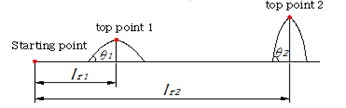
Fig. 4Scaled test path

a) First experiment
b) Second experiment
For the purpose of verifying and revising control model, we programmed the microcontroller to set a series of fixed speed and steering inputs. Thus, identical experiment can be repeated many times. For the first experiment, one obstacle is put 2.5 m in the front of starting point, the route of this experiment is show in Fig. 4. The pitch angle of obstacle is 22.5°. In this case, vehicle comes close to tip-over. The scaled vehicle differential speed curve, which is controlled by active safety control algorithm (ASC), is shown in Fig. 5.
Fig. 5Scaled vehicle differential speed curve and 2-axis angle with ASC
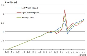
a) The speed of each wheel
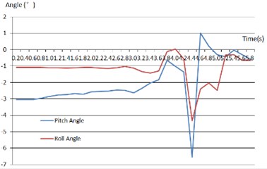
b) Pitch and roll angle of vehicle
From above results, when scaled vehicle cross obstacle, ASC make an important effort to adjust the differential speed between right and left wheel, which can verify scaled vehicle body to be stability.
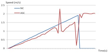
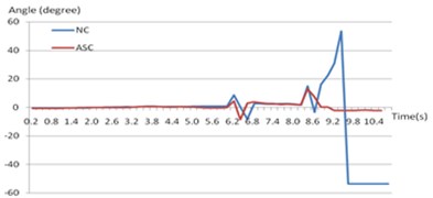
For the second experiment, we put two obstacles on the front route of the vehicle, the scaled vehicle follow path as shown in Fig. 3(b). The first pitch angle is about 13.5° and 1.5 m distance from starting point. The second one is about 23.5° and 2.8 m distance from starting point. The contrast experimental results of ASC and non-control (NC) are shown in following picture.
Fig. 6 is shown variation of pitch angle and average speed when scaled vehicle cross obstacles. If the vehicle was not controlled by active safety control algorithm, at first obstacle it can cross without any violent fluctuate of speed and pitch angle. But it fails to cross the second obstacle and tip-over in the end, which can be implied by pitch angle results. On the contrary, ASC control acceleration of scaled vehicle, pitch angle is adjusted and cross two obstacles successfully.
Fig. 6Contrast curve of Non-control (NC) and Active Safety Control (ASC)
a) Pitch angle contrast curve
b) Average speed contrast curve
5. Conclusions
In this paper, a 5-DOF dynamic rollover and tip-over model of orchard vehicle is established as theoretical model working for control method. After that, using Kalman prediction method, the active safety control algorithm is structured, which control 2-axis can accelerate and body posture of vehicle to prevent rollover and tip-over accident. Finally, scaled experimental system was set up, and scaled test prove feasibility and operability of algorithm.
References
-
Kim H. J., Park Y. P. Investigation of robust roll motion control considering varying speed and actuator dynamics. Mechatronics, Vol. 14, 2004, p. 35-54.
-
Trent V., Greene M. A genetic algorithm predictor for vehicle rollover. IECON 02, IEEE 28th Annual Conference, 56, p. 60-2002.
-
Wang Xin, Zhao Siqi, Wang Liyang Xu Songbing, Wang Shumao Stability control method for orchard vehicle. Transactions of the Chinese Society for Agricultural Machinery, Vol. 46, Issue 5, 2015, p. 13-19.
-
Wang Xin, Fu Han, Chen Du, Wang Shumao Anti-interference optimal design of grain combine harvester multiple target working speed control mode. Materials Processing and Manufacturing Vol. 3, 2013, p. 23-26.
-
Mao Xu, Wang Xin, Zhang Junchao, Chen Kai Design of electric orchard vehicle four-wheel steering control system. Applied Mechanics and Materials, 2013, p. 245-248.
-
Thambiratnam D. P., Clark B. J., Perrera N. J. Performance of a rollover protective structure for a bulldozer. Journal of Engineering Mechanics, Vol. 135, Issue 1, 2009, p. 31-40.
-
Clark B. J., Thambiratnam D. P., Perera N. J. Enhancing the impact energy absorption in rollover protective structures. International Journal of Crashworthiness, Vol. 13, Issue 2, 2008, p. 167-183.
-
Clark B. J. The Behaviour of Rollover Protective Structures Subjected to Static and Dynamic Loading Conditions. Queensland University of Technology, Brisbane, 2006, p. 122-126.
-
Wang Ling, Wang Xin, Wang Shumao Development of feeding rate detection sensor based on wireless technology. Applied Mechanics and Materials, Vol. 229, Issue 231, 2012, p. 1272-1275.
-
Kluga J. Dynamic data processing with Kalman filter. Electronics and Electrical Engineering, Technologija, Kaunas, Vol. 5, Issue 111, 2011, p. 33-36.
-
Wang Ling, Wang Xin, Liu Jian, Wang Shumao Research on flexible remote monitoring system of agricultural machinery based on virtual instrument. Transactions of the Chinese Society for Agricultural Machinery, Vol. 45, Issue 1, 2014, p. 34-39.
-
Guo J., Jafarkhani H. Sensor deployment with limited communication range in homogeneous and heterogeneous wireless sensor networks. IEEE Transactions on Wireless Communications, Vol. 15, Issue 10, 2016, p. 6771-6784.
-
Li Weiwei, Tian Lintao, Zhang Shaohong, Wang Shumao, Wang Xin Tip-over stability analysis of orchard vehicle with dynamic simulation method. 4th International Symposium on Electrical and Electronics Engineering, 2015, p. 1029-1034.
-
Pastor Marek, Dudrik Jaroslav Predictive control of grid-connected multilevel inverter with output LCL filter. Electronics and Electrical Engineering, Technologija, Kaunas, Vol. 21, Issue 3, 2015.
-
Prascevic M., Cvetkovic D., Mihajlov D., Petrovic Z., Radicevic B. Verification of NAISS model for road traffic noise prediction in urban areas. Electronics and Electrical Engineering, Technologija, Kaunas, Vol. 19, Issue 6, 2013.
-
Levisauskas D., Tekourius T. Investigation of P and PD controllers’ performance in control systems with steady-state error compensation. Electronics and Electrical Engineering, Vol. 121, Issue 5, 2012, p. 63-68.
About this article
Program for The National Natural Science Fund (Grant No. 51405492), Beijing Municipal Science and Technology Commission Project (Grant No. D151100003715001) and Chang Jiang Scholars and Innovative Research Team in University of China (Grant No. IRT13039).
