Abstract
Methods to harvest energy that is wasted during road vehicle operation have been studied in recent years. Mechanical vibrations from vertical motion induced by road bumps dissipate a large amount of energy. A linear electric generation system is presented to harvest this energy. The system uses mechanical resonance to maximize the efficiency of harvesting. A shock absorber suspension and electric generator mathematical model were created to analyze the vibration characteristics induced by road bumps during vehicle operation. An electromagnetic simulation using the commercial software MAXWELL (Ver. 13, ANSOFT, USA) was performed to predict the electricity generation. Finally, the magnetic circuit design was optimized to improve the amount of electricity generated. The results demonstrate the possibility of using the proposed approach in practical applications.
1. Introduction
Hybrid cars and electric cars use an electric motor as the main driving source, and they get their power from rechargeable batteries installed inside the car. These batteries, however, are not only used to power the car but also used for the functioning of lights and wipers. Electric cars have more batteries than normal gasoline car. Therefore, energy harvesting technologies that have been developed over the past decade include thermal energy harvesting from the brakes (regenerative braking systems), high temperature heat harvesting from the engine (thermal conversion systems) and so on [1-3]. However, most of the technologies produce only a small amount of electric energy and have unstable energy harvesting since the operation environment is intermittent. Thus, energy harvesting technologies that convert vibration energy when the vehicle is running into electric energy are attracting much interest in research. Vibration energy harvesting is performed by various devices [4-6]. Waterbury et al. introduced vibration energy harvesting from the unsprung suspension of a vehicle for asset monitoring using an electromagnetic transducer [7], and Lei et al. designed and characterized electromagnetic energy harvester for vehicle suspension [8, 9]. Those suggested the structure of energy harvester installation parallel with mechanical damper in vibration suspension system of a vehicle which results in spatial problem for installation of electromagnetic harvester due to confined space of vehicle suspension system.
Therefore, we propose a novel compact structure of electromagnetic regenerative suspension system to combine electric generator with mechanical suspension. In addition, the optimal design is performed to maximize the electric generation to compensate the loss of electric generation due to less size of electric generator. Vibration displacement analysis was performed and then transient analysis of the electric generation was performed using the commercial electromagnetic analysis software MAXWELL (Ver. 13, ANSOFT, USA). Lastly, design optimization was performed for stable and improved generation using PIAnO process integration, automation, and optimization (PIDO) software (Ver. 4, PIDOTECH, KOREA).
However, this approach has possible difficulties in obtaining efficient generation when the road is smooth. Therefore, we propose a resonance linear electric generator that uses vertical vibration energy from a vehicle suspension to overcome such limitations. The system is installed in the suspension. Vibration energy can be stably harvested from a small vibration input. This paper describes the structure and principles of the coupled system of a suspension and the generator. Vibration displacement analysis was performed using MATLAB, and then transient analysis of the electric generation was performed using the commercial electromagnetic analysis software MAXWELL (Ver. 13, ANSOFT, USA). Lastly, design optimization was performed for stable and improved generation using PIAnO process integration, automation, and optimization (PIDO) software (Ver. 4, PIDOTECH, KOREA).
2. Resonance linear electric generator with suspension system
The input energy from the road surface applies random vibration to the suspension system due to frequently changing road conditions, but not regular vibration. Therefore, the average road conditions and the input vibration frequency should be identified. A general asphalt road was used as the standard operating condition, and the average input vibration frequency was set to about 4 Hz [10].
Fig. 1 shows a vehicle suspension system that is affected by road vibration due to an irregular road surface. Differences in road elevation between paved and unpaved roads are shown in Fig. 2 [11]. An electric generator system was applied to the suspension on one of the wheels. This one-quarter model is typically used in the design process of a lower vehicle body and its components
Fig. 1Vibration system with road vibration
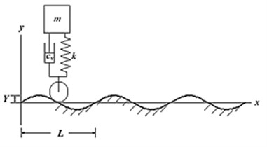
Fig. 2Various elevation displacements for different road surfaces
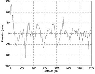
a) Unpaved road
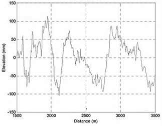
b) Highway (asphalt)
This model can neglect torsional vibration and the rolling motion of the vehicle body. Fig. 4 shows a schematic diagram of the suspension and generator. The size of the linear electric generator was roughly determined by considering the diameter of the suspension spring. The shaft that supports the moving part of the electric generator is the suspension damper.
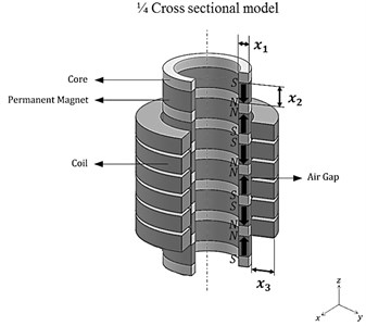
The moving part of the linear electric generator consists of permanent magnets with the pole arrangement shown in Fig. 4. A core act as a yoke by connecting the permanent magnets. The electromagnetic coil and electromagnetic coil housing surround the moving part as a stator with a fixed air gap spacing. The numbers of moving parts and vertical size of the moving parts and the stator were determined based on the two-pole three-phase structure that optimized the electrical array of the electric generator.
Fig. 3Diagram of suspension with linear electric generator
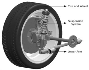
a) Suspension system
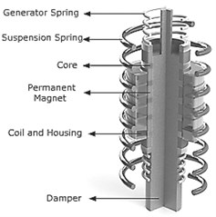
b) Electric generator in suspension
Fig. 4Schematic diagram of electric generator with pole arrangement
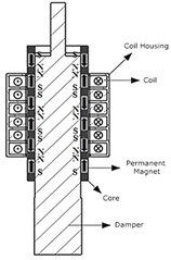
a) Cross-sectional diagram
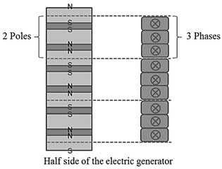
b) Two-pole three-phase arrangement
3. Mechanical analysis
Prior to analyzing the performance of the generator system, vibrational modeling was conducted. The vibration system has a 3 degrees of freedom (DOF) system with three representative masses. The system can be expressed as 3-DOF vector matrix equations and can be arranged as a state space equation for the vibration displacement analysis.
3-DOF vibration system:
State space:
Damping coefficient of the electric generator:
, , and are the masses of the suspension, electric generator, and vehicle body, respectively. This information was obtained from a Hyundai Sonata to create the vibration system. The spring constant k was also provided by the manufacturer (Mando Suspension, KOREA). The spring constant of the electric generator was determined to obtain the average input frequency 4 Hz from the road profile based on the natural frequency equation . The damping coefficient of the suspension was given by the manufacturer (Mando Suspension, KOREA). The damping coefficient of the electric generator was calculated using Eq. (3). , , and denote the flux density in the air gap between the moving part and the electromagnetic coil winding, electromagnetic coil length, and electromagnetic coil resistance, respectively.
Fig. 5Free body diagram of the electric generator and the applied suspension system
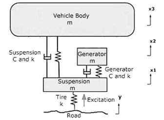
Table 1Data for the vibration system
Mass (kg) | Damping coefficient (kg/s) | Spring constant (N/m) | |
Tire (and wheel) | None | None | 190.000 |
Suspension | 59 | 798 | 16.182 |
Electric generator | (25 values for each design model) | ||
Vehicle body | 290 | None | None |
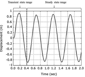
To determine the input far the transient electric generation analysis, a vibration analysis was conducted using MATLAB to find the displacement of the electric generator with a vibration system consisting of , , and . Displacement of the mass of the electric generator was simulated and differentiated to determine the velocity. This value was used as the input for the transient analysis. Fig. 6 shows the results of the vibration analysis and the equation of the input velocity.
Input velocity (m/s):
Fig. 6Displacement result of the electric generator
4. Electromagnetic analysis
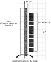
Transient analysis was performed using the commercial electromagnetic finite element analysis software MAXWELL (VER. 13, ANSOFT, USA) to confirm the normal operation of the linear electric generator. Fig. 7 shows the MAXWELL finite element model of the electric generator and the external circuit. Due to the 3-D shape of the electric generator (a symmetric cylindrical structure), the model was analyzed using 2-D analysis and was reduced to only one half of the permanent magnets, cores, and coil while neglecting the housing, spring, and damper shaft.
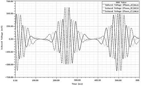
Since the electric generator has two poles and three phases, a graph of results was made for each of the three electromagnetic coil windings during the analysis process. Differences in the generation results occurred due to the initial position of each moving part and the electromagnetic coil winding pair. These characteristics are shown in the graph in Fig. 8. The analysis was conducted by modeling the entire covered mesh using triangle elements with a length of 0.1 mm on one side. The entire analysis time was 0.6 s for about 1.5 cycles of electric generation motion with a time step of 1/200 s. The induced voltage from the three electromagnetic coil windings in the analysis model was 0.623 V (peak value), and the average RMS values were 0.205, 0.202 and 0.196 during the generation process.
Fig. 7Finite element model of the electric generator and external circuit for transient analysis
a) Finite element model
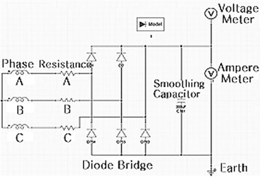
b) External circuit
Fig. 8Electric generation results
5. Design optimization
The generation performance of linear electric generators should be improved to satisfy increasing demands from automotive electronics and to realize a sufficient recharge capability for standby power systems. An optimum design is also required for practical use in mass production vehicles. A design formulation for optimization was determined with maximization of the gross generation of the electric generator as an objective function. The design variables were the main elements of the moving parts of the electric generator, permanent magnets, core thickness, permanent magnet height, and Optimum design formulation:
Cost function: Maximization of gross generation power.
Design variables: (a) Thickness of permanent magnets and cores; (b) Height of permanent magnets; (c) Thickness of the coil.
Constraints: (a) Total Length of Mover (300 mm); (b) Maximum Radial Length (150 mm); (c) Assume that Diameter of the Coil is 1.02 mm (AWG #18).
Misc.: (a) is the height of the damper (300 mm); (b) is the diameter of the damper assembly (150 mm).
Fig. 9Design variables in a mover of the electric generator
The specifications of the 25 electric generator models were determined in order to activate the resonance phenomena during operation. Regardless of the size, height, or thickness of the permanent magnets and cores, each mass value satisfies the natural frequency formula (, which can improve the generation performance. The spring constant was also manipulated in response to the natural frequency formula using MATLAB. The electric generators with various specifications were modeled as shown in Fig. 9. Each gross generation was predicted using transient analysis in MAXWELL (VER. 13, ANSOFT, USA). The overall trend of the predicted values and the correlation of the design variables were determined as a standardized mathematical meta-model, which can represent design models using the Kriging method. Based on this meta-model, the optimum design values that satisfy the maximum gross generation were derived by creating of each design variable with various specifications, eliminating culled models, and selecting dominant models using an evolutionary algorithm [12, 13].
Table 225 Simulation models for optimization
(Thickness of PM and core) | (Height of PM) | (Thickness of electromagnetic coil) | |
1 | 5 | 10 | 5 |
2 | 5 | 20 | 16.25 |
3 | 5 | 30 | 27.5 |
4 | 5 | 40 | 38.75 |
5 | 5 | 50 | 50 |
6 | 13.75 | 10 | 16.25 |
7 | 13.75 | 20 | 27.5 |
8 | 13.75 | 30 | 50 |
9 | 13.75 | 40 | 5 |
10 | 13.75 | 50 | 38.75 |
11 | 22.5 | 10 | 27.5 |
12 | 22.5 | 20 | 50 |
13 | 22.5 | 30 | 38.75 |
14 | 22.5 | 40 | 16.25 |
15 | 22.5 | 50 | 5 |
16 | 31.25 | 10 | 38.75 |
17 | 31.25 | 20 | 5 |
18 | 31.25 | 30 | 16.25 |
19 | 31.25 | 40 | 50 |
20 | 31.25 | 50 | 27.5 |
21 | 40 | 10 | 50 |
22 | 40 | 20 | 38.75 |
23 | 40 | 30 | 5 |
24 | 40 | 40 | 27.5 |
25 | 40 | 50 | 16.25 |
Table 3Transient analysis results for 25 models
Model | Induced voltage (mV) | Model | Induced voltage (mV) |
1 | 271.57 | 13 | 1390.98 |
2 | 385.71 | 14 | 1671.48 |
3 | 591.23 | 15 | 1427.22 |
4 | 711.54 | 16 | 993.25 |
5 | 1001.37 | 17 | 1376.79 |
6 | 344.15 | 18 | 2089.49 |
7 | 938.45 | 19 | 2401.32 |
8 | 1102.67 | 20 | 2863.1 |
9 | 849.33 | 21 | 1102.95 |
10 | 1205.49 | 22 | 1426.52 |
11 | 995.41 | 23 | 2074.88 |
12 | 1054.23 | 24 | 2511.57 |
25 | 3106.56 |
The entire optimum design process was performed using the PIDO software PIAnO based on theoretical optimum design methods [14]. Table 2 shows the 25 cases of simulation models for the optimization process. Based on these models, the heights of the core and coil and the turns of the coil were calculated to adjust the electric generator to satisfy the structure of two poles and three phases. Table 3 shows the transient analysis results, and Table 4 shows the optimum values of each design variable from the PIAnO design optimization analysis.
Table 4Optimum design variables
(Thickness of PM and core) | (Height of PM) | (Thickness of electromagnetic coil) | |
Optimum value | 38.4 mm | 49.4 mm | 16.4 mm |
6. Conclusions
Ongoing efforts are being made to harvest energy from vehicles using various ideas and technologies. Vibration energy has more potential than other sources for energy harvesting. We proposed the novel compact structure of electromagnetic regenerative suspension system to combine electric generator with mechanical suspension. The performances are verified in vibration analysis, electromagnetic analysis and optimal design. The following conclusions were drawn our results.
The mathematical vibration model of electromagnetic regenerative suspension system is created to predict the dynamic characteristic of armature by road bump. The information for vibration analysis was given by the manufacturer “Mando Suspension”.
The electromagnetic analysis by vibration data entry is performed to calculate the electric generation in three electromagnetic coil windings using commercial electromagnetic analysis software “MAXWELL”.
The optimal design is performed to maximize the electric generation to compensate the loss of electric generation due to less size of electric generator. The optimum design process was performed using PID software PIAnO. The design variables are thickness of permanent magnets and cores, height of permanent magnets and thickness of coil. In result, the gross electric generation magnify 5 times of initial model.
References
-
Manla G., White N. M., Tudor J. Harvesting energy from vehicle wheels. Solid-State Sensors, Actuators and Microsystems Conference, 2009, p. 1389-1392.
-
Wischke M., Masur M., Woias P. A hybrid generator for vibration energy harvesting applications. Solid-State Sensors, Actuators and Microsystems Conference, 2009, p. 521-524.
-
Dayal S., Dwari S., Parsa L. Maximum energy harvesting from vibration-based electromagnetic micro generator using active damping. Institute of Electrical and Electronics Engineers, Vol. 46, Issue 5, 2010, p. 371-373.
-
Sterken T., Fiorini P., Altena G., Van Hoof C., Pures R. Harvesting energy from vibrations by a micromachined electret generator. 14th International Conference on Solid-State Sensors, Actuators and Microsystems, 2007, p. 1681-1684.
-
Blystad Lars-Cyril Julin, Halvorsen Einar, Husa Sevin Piezoelectric MEMS energy harvesting systems driven by harmonic and random vibrations. Institute of Electrical and Electronics Engineers, Vol. 57, Issue 4, 2010.
-
Wischke M., Masur M., Woias P. A hybrid generator for vibration energy harvesting applications. Tranduces, 2009.
-
Waterbury A. C., Lin S. D., Wright P. K. Vibration energy harvesting from the unsprung suspension of a vehicle for asset monitoring using an electromagnetic transducer. PowerMEMS, 2012.
-
Zou Lei, Scully Brian, Shestani Jurgen, Zhou Yu Design and characterization of an electromagnetic energy harvester for vehicle suspensions. Smart Materials and Structures, 2010.
-
Zou Lei, Zhang Pei-Sheng Energy harvesting, ride comfort, and road handling of regenerative vehicle suspensions. Journal of Vibration and Acoustics, Vol. 135, 2013, p. 011002-1.
-
Gillespie T. D. Fundamentals of Vehicle Dynamics. Society of Automotive Engineers Inc., 1992.
-
Braz J. Vehicle dynamic response due to pavement roughness. Journal of the Brazilian Society of Mechanical Sciences and Engineering, Vol. 33, Issue 3, 2011.
-
Papalambros P. Y., Wilde D. J. Principles of Optimal Design: Modeling and Computation. Cambridge University Press, Cambridge, 2000.
-
Dette H., Lopez I. M. Maximin efficient design of experiment for exponential regression models. Journal of Statistical Planning and Inference, Vol. 136, Issue 12, 2006, p. 4397-4418.
-
Park C. H. PIAnO (Process Integration, Automation and Optimization) User’s Manual 3.6. 1st Edition, PIDOTECH. Seoul, 2013.
Cited by
About this article

This work was supported by Civil-Military Technology Cooperation Program (No. 16-CM-EN-17) funded by the Defense Acquisition Program Administration and the Ministry of Trade, Industry and Energy in Korea.
