Abstract
The vibration characteristics of stators of bearingless switched reluctance motors (BSRMs) are analyzed based on finite-element method (FEM) in this paper. Aiming at to overcome the limitations of the previous modal analysis in which the influence of stator windings on the natural frequencies of switched reluctance motors (SRMs) stators is treated simply as an additional mass, the finite-element (FE) model of a 12/8-pole BSRM stator which takes torque windings and suspension windings in account is constructed based on its real structural model. In this paper, a kind of method is proposed to connect the windings and stator core as well as torque windings and suspension windings through the contact whose type is bonded. The validity of the connection method is proved by three-dimension (3D) finite-element analysis (FEA) and experimental modal analysis results of the SRM prototype.
1. Introduction
Switched reluctance motors(SRMs) have many outstanding advantages, such as a simple structure and strong ability of fault tolerant, reliable operation under phase-lacking, which is tolerant to harsh environments and suitable for working at high speed. However, SRMs compared with other traditional motors have relatively higher level of noise and vibrations which limits its popularization and application [1, 2]. Therefore, many academics focus on how to reduce the noise and vibrations of SRMs.
Bearingless switched reluctance motors (BSRMs) have two sets of windings on a stator pole, one is torque winding and another is suspension winding which is used to generate levitation force. BSRMs can realize rotation and levitation functions at the same time through the control of two sets of windings [3, 4]. The development of BSRMs has broad prospects. However, as a special kind of SRMs, the vibrations and noise problem also restrict the application of BSRMs.
Research showed that the acoustic noise measured around an SRM is found to be directly related to the radial vibration of the stator core due to the radial magnetic force. The vibration and resulting acoustic noise is particularly severe when stator resonance occurs, i.e., when the frequencies and waveforms of radial magnetic forces coincide with the normal mode shapes and natural frequencies [5-7]. Therefore, it is important to predict the natural frequencies and vibration characteristic of BSRMs, in order to reduce the vibration and noise of motors.
At present, there are two kinds of methods to calculate natural frequencies theoretically. (1) analytical calculation method [8-10]. This kind of method can get the analytical expressions of natural frequencies, but its precision is poor. (2) numerical calculation method. Finite-element method(FEM) [11-16] is an effective numerical method, and is widely used in the study of the motors due to the results of modal analysis can be calculated quickly, correctly and intuitively.
In previous work, many researchers used FEM to obtain natural frequencies of SRMs. In the early time, stator core was the only model to be considered [11, 12]. Several different shapes of stator cores were analyzed in reference [13]. Further, some researchers were concerned about the contribution of windings. The windings were treated as additional mass by some investigators [14], while others did not account for them in the natural frequencies calculations. At the same time, references [14, 15] investigated the influence of frame, radiating rib, terminal box, and end bell on the natural frequencies. The mounting effects on natural frequencies were analyzed in reference [16].
Currently, published literatures are focused on decreasing vibration and acoustic noise of SRMs. There is no previous work on the effect of torque winding and suspension winding on the BSRMs stator natural frequency characteristics. Modeling the torque windings and suspension windings, and computing their influence on the BSRM stator vibration is the new contribution in this paper. In order to obtain the natural frequencies and corresponding vibration modes of BSRM stator accurately, this paper presents a new connection method which is using contact whose type is bonded to connect the windings and stator core as well as torque windings and suspension windings. A hammering measurement method is employed to measure the natural frequencies. Three-dimensional(3D) finite-element analysis(FEA) and modal experiment results of a 6/4-pole SRM prototype validate that the new connection method can improve the modeling accuracy.
2. 3D modal analysis of an SRM
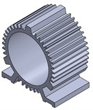
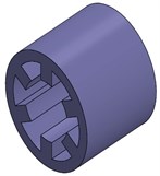
A 0.75-kW SRM experimental prototype with three-phase and 6/4-pole is used as the object of the modal calculations shown in Fig. 1.
Fig. 1The structure of a 6/4-pole SRM experimental prototype: a) shell which contains ribbed frame and base, b) stator, c) windings, d) a 6/4-poles SRM
a)
b)
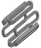
c)
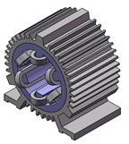
d)
2.1. Finite-element model of SRM stator
Based the SRM experimental prototype, 3D finite-element(FE) model of the SRM stator is built which takes windings in account. The FE model of the SRM wound stator which takes shell and ribbed frame and base in account is shown in Fig. 2. Table 1 shows the effective material properties of stator core, windings and shell which contains ribbed frame and base.
Fig. 23D FE computing model of the SRM stator
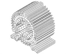
Table 1Material properties
Young’s modulus / Pa | Density / kg·m-3 | Poisson’s ratio | |
Shell | 0.9×10¹¹ | 7640 | 0.25 |
Windings | 1.2×10¹¹ | 8900 | 0.3 |
Stator Core | 2.05×10¹¹ | 7800 | 0.3 |
2.2. Modal analysis and its results
For an actual SRM, because the gap between the poles and windings is full with insulating resin, windings can move with the stator core. However, a gap is existing between stator poles and winding in the FE model of the SRM stator. In order to consider the influence of windings on natural frequencies of stator more reasonably, this paper puts forward a new connection method which is using contact whose type is bonded to connect the windings and stator core. More specifically, bonded is chosen as one of the contact types. In the meanwhile, Pinball radius is defined by ANSYS Workbench's own Program Controlled. In the process of free vibration, if the gap between stator core and winding is less than Pinball radius, they are bonded; otherwise they're both in a state of freedom without constraints.
FE software ANSYS Workbench is used to analyze free vibration modal of the SRM stator which is using the above winding connection method. Because the exciting force mainly happens on the yoke of the stator, vibration modes which have no axial deformations make contribution to acoustic noise. Due to the low-order vibration modes are the main vibration modes, this paper only lists the low-order vibration modes and corresponding natural frequencies.
Modal calculation results show that when the gap is less than 1.5 mm, ANSYS Workbench’s own Program Controlled can get effective modes. Table 2 lists low-order natural frequencies under different gap width. As shown in Table 2, there are no difference between natural frequencies of the low-order vibration modes. Therefore, the FE model of SRM stator which the gap between winding and stator core is 0.5 mm is selected for free vibration modal analysis in this paper. Vibration mode shapes are presented graphically in Fig. 3, which shows the 2nd, 3rd and 4th mode shapes.
Table 2Natural frequencies under different gap width
Gap width / mm | Natural frequencies / Hz | |||||||
Second-order | Third-order | Forth-order | ||||||
0.3 | 1886.9 | 1907 | 2170.6 | 2291 | 4641.7 | 5786.6 | 8339.8 | 8487.8 |
0.5 | 1886.6 | 1905.9 | 2170 | 2290.6 | 4639.2 | 5782.7 | 8317.9 | 8465.1 |
0.8 | 1886.1 | 1905.7 | 2169.2 | 2290.1 | 4635.2 | 5776.1 | 8277.5 | 8422.9 |
1.2 | 1885.5 | 1905.4 | 2168.1 | 2289.4 | 4629.9 | 5767.4 | 8218.4 | 8360.8 |
1.5 | 1885.5 | 1905.2 | 2167.3 | 2288.8 | 4626.1 | 5760.2 | 8164.3 | 8305 |
Fig. 3Low-order modal shapes of the 6/4-pole SRM prototype
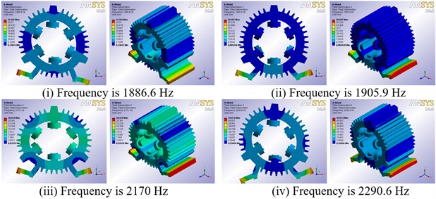
a) Second-order modal shapes
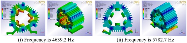
b) Third-order modal shapes
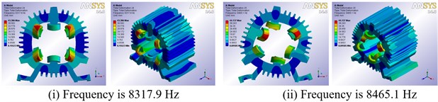
c) Forth-order modal shapes
2.3. Experiments
In order to validate the effectiveness of connection method which is using contact whose type is bonded to connect the windings and stator core, experimental modal analysis is applied for the SRM prototype based on the random signal and vibration analysis system (CRAS). The 6/4-pole SRM prototype is motivated in multiple-points and the output signal is picked up in one point using hammering method. Fig. 4 shows the frequency response curve which is obtained by modal experiments. Low-order vibration mode shapes obtained by experiment are shown in Fig. 5, the corresponding frequencies is 1633.30 Hz, 2285.16 Hz, 2031.86 Hz and 2922.36 Hz. Because hammering method can only obtain comparatively accurate low-order modal modes, this paper gets only frequency response characteristics within 4000 Hz.
3D FEA results are listed in Table 3. In order to validate the effectiveness of the modeling method proposed in this paper, the 3D FEA results of the SRM model whose windings are ignored are also shown in Table 3. Compared with modal experiment results, 3D FEA of the SRM model which takes the windings in account have more accurate results than those which ignores the influence of the windings. Therefore, the proposed method which is using contact whose type is bonded to connect the windings and stator core is effective and workable.
Fig. 4Frequency response curve obtained by experiments
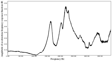
Fig. 5Vibration mode and natural frequencies of modal experiment
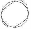
a) 1633.30 Hz
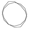
b) 2031.86 Hz
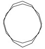
c) 2285.16 Hz
d) 2922.36Hz
Table 3Stator natural frequencies of 3D FEA
Vibration mode | Calculation methods of natural frequencies / Hz | |||||||
3D FEA | ||||||||
Windings are considered. | Windings are not considered. | |||||||
Second-order | 1886.6 | 1905.9 | 2170 | 2290.6 | 1928.7 | 1980.7 | 2337.8 | 2407.3 |
Third-order | 4639.2 | 5782.7 | 5204.3 | 6177.1 | ||||
Forth-order | 8317.9 | 8465.1 | 9367.1 | 10005 | ||||
3. 3D modal analysis of a BSRM
3D FEA and modal experiment results of the SRM prototype show that the connecting method proposed in paper can improve the accuracy of FE modeling of the SRM stator, so this method can be applied to 3D FEA of BSRM.
3.1. Finite-element model of BSRM stator
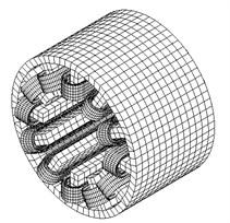
In this paper, 3D FE model of stator of a 12/8-pole BSRM which takes torque windings and suspension windings in account is constructed [17]. 3D FE model of the wound stator of BSRM is shown in Fig. 6.
Fig. 63D FE computing model of BSRM stator
3.2. Modal analysis and its results
Compared with the SRM, there are two sets of windings entwined around the stator of BSRM. Therefore, the connection not only exists between the windings and stator core, but also between torque windings and suspension windings. According to the above mentioned connection method, the connection between winding and stator core is realized by defining the contacts whose type is bonded. The same connection method is used to connect torque windings and suspension windings. FE software ANSYS Workbench is used to measure the vibration modes and natural frequencies of the BSRM stator which takes torque windings and suspension windings in account among the range of stated frequency. Vibration mode shapes which have no axial deformations are presented graphically in Fig. 7, which shows the 2nd, 3rd, 4th mode shapes.
Fig. 7FE vibration modes of the BSRM
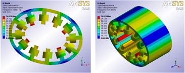
a) 2nd mode shape frequency is 709.67 Hz
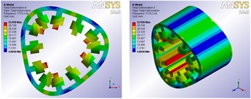
b) 3rd mode shape frequency is 1779.3 Hz
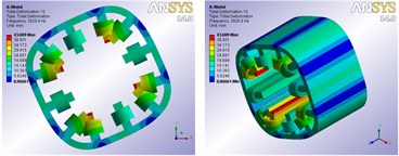
c) 4th mode shape frequency is 2928.8 Hz
Fig. 7 shows that after bonded is used to connect the windings and stator core as well as torque windings and suspension windings, two sets of windings can move with the stator core during the process of free vibration, and the vibration mode shapes are clear. The 3D FEA results confirm that the connection method can make the windings have a significant effect on the natural frequencies of the stator, and obtain more accurate natural frequencies and corresponding modal vibration modes of the BSRM stator.
4. Conclusions
In this paper, 3D FE model of stator of a 6/4-pole SRM which takes windings in account is constructed by using FE software ANSYS Workbench. Bonded as one kind of the contact types is used to connect the windings and stator core. Based on FEM, modal parameters of the SRM stator are obtained. The validity of the connection method is proved by 3D FEA and experimental modal analysis results of the SRM prototype. In order to consider the influence of torque winding and suspension winding on mass and stiffness of BSRM stator reasonably, the connection method which is using contact whose type is bonded to connect the windings and stator core as well as torque windings and suspension windings is applied in the 3D FEA of a 12/8-pole BSRM. The 3D FEA results show that the introduction of this connection method can improve the modeling accuracy of BSRM stator, which laid a foundation for reducing vibration and acoustic noise.
References
-
Masoudi K., Feyzi M. R., Masoud A. Reduction of vibration and acoustic noise in the switched reluctance motor by using new improved stator yoke shape. IEEE Electrical Engineering, 2013, p. 1-4.
-
Gan C., et al. Investigation of skewing effects on the vibration reduction of three-phase switched reluctance motors. IEEE Transactions on Magnetics, Vol. 51, Issue 9, 2012.
-
Yang Y., Deng Z., Zhang Q., et al. Stator vibration analysis of bearingless switched reluctance motors. IEEE International Conference on Electrical and Control Engineering, 2010, p. 1993-1996.
-
Liu C., Yang Y., Deng Z. Vibration control strategy for bearingless switched reluctance motors. 17th International Conference on Electrical Machines and Systems (ICEMS), 2014, p. 1675-1680.
-
Cameron D. E., Lang J. H., Umans S. D. The origin and reduction of acoustic noise in doubly salient variable-reluctance motors. IEEE Transactions on Industry Applications, Vol. 28, Issue 6, 1992, p. 1250-1255.
-
Wu C. Y., Pollock C. Analysis and reduction of vibration and acoustic noise in the switched reluctance drive. IEEE Transactions on Industry Applications, Vol. 31, Issue 1, 1995, p. 91-98.
-
Pillay P., Cai W. An investigation into vibration in switched reluctance motors. IEEE Transactions on Industry Applications, Vol. 35, Issue 3, 1999, p. 589-596.
-
Anwar M. N., Husain I. Radial force calculation and acoustic noise prediction in switched reluctance machines. IEEE Transactions on Industry Applications, Vol. 36, Issue 6, 2000, p. 1589-1597.
-
Cai W., Pillay P., Omekanda A. Analytical formulae for calculating SRM modal frequencies for reduced vibration and acoustic noise design. IEEE International Electric Machines and Drives Conference (IEMDC), 2001, p. 203-207.
-
Grabner C., Hajdarevicl I. Analytical and numerical approaches for the prediction of resonance frequencies of a switched reluctance machine. 2nd International Conference on Power Electronics, Machines and Drives (PEMD), 2004, p. 392-397.
-
Lee J. H., Lee Y. H., Kim D. H., et al. Dynamic vibration analysis of switched reluctance motor using magnetic charge force density and mechanical analysis. IEEE Transactions on Applied Superconductivity, Vol. 12, Issue 1, 2002, p. 1511-1514.
-
Zhang H., Gao R., Zhang J., et al. Vibration analysis for switched reluctance motor system based on finite element and FFT. IEEE International Conference on Mechatronics and Automation, 2009, p. 4257-4261.
-
Cai W., Pillay P., Omekanda A. Low vibration design of SRMs for automotive applications using modal analysis. IEEE International Electric Machines and Drives Conference, 2001, p. 261-266.
-
Cai W., Pillay P., Tang Z. Impact of stator windings and end-bells on resonant frequencies and mode shapes of switched reluctance motors. IEEE Transactions on Industry Applications, Vol. 38, Issue 4, 2002, p. 1027-1036.
-
Sun J., Zhan Q., Wang S., et al. A novel radiating rib structure in switched reluctance motors for low acoustic noise. IEEE Transactions on Magnetics, Vol. 43, Issue 9, 2007, p. 3630-3637.
-
Tang Z., Pillay P., Omekanda A. M. Analysis of mounting effects on vibrations of switched reluctance motors. IEEE International Electric Machines and Drives Conference, Vol. 1, 2003, p. 97-103.
-
Yang Y., Deng Z. Q., Yang G., et al. A control strategy for bearingless switched-reluctance motors. IEEE Transactions on Power Electronics, Vol. 25, Issue 11, 2010, p. 2807-2819.
About this article
This work was supported by the National Natural Science Foundation of China (No. 51477042).
