Abstract
Economic feasibility and cost minimizing of experimental setups is one of the most important factors in many research and this is no different for active noise control (ANC) in ducts. Cheaper acquisition and assembly of equipment is desirable, provided you keep the same efficiency of acquisition, filtering, control and attenuation. This study aims to compare the performance of low cost microphones with precision microphones, when applied to the acoustic control system in feedforward configuration. This system makes use of a control board with Digital Signal Processor (DSP) in order to identify, analyze and compare systems of acoustic control in real time. To validate the performance of the sensors, an experimental bench was setup, which included a PVC duct and speakers as noise source and actuator. Microphones are the error and reference sensors. The system performance is obtained by a sound pressure meter acting on the outlet duct.
1. Introduction
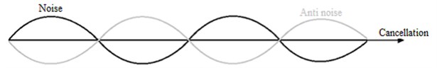
Active Noise Control (ANC) reduce sound pressure levels (SPL) and is a system that involves acoustic concepts, components and electronics. It is based on the generation of a signal “anti-noise” of equal amplitude and opposite phase, superimposed to the primary sound (unwanted sound), resulting in attenuation or cancellation of both. According to Bistafa [1], the performance of the cancellation of the primary noise depends on the accuracy in amplitude and phase of the generated anti-noise. In Fig. 1 shows the superposition of two sound waves, which results in a sum of zero or attenuated value.
The ANC system acts with great efficiency at low frequencies and have a reduced installation volume. This system may have various applications and can be used together with a passive technique, resulting in hybrid control solutions [2].
An active control system was adjusted to attenuate noise in duct. Will be presented a comparison between precision microphones and inexpensive microphones when applied to this system.
Fig. 1Sum of sound waves resulting in the cancellation of both
2. Active noise control
One of the most important types of active noise controllers are the feedforward controllers. It is used on the cancellation of both narrowband noise (periodic noise) and broadband noise (random noise) [3]. Another important factor is that the feedforward controls the reference noise is felt before spreading through the speaker of cancellation [4].
2.1. Feedforward control
In ventilation and exhaust systems a wide range of broadband noise is produced in their ducts. Such systems are evaluated by the construction of similar systems in laboratories compounds commonly by a noise source (noise generator), a reference sensor (microphone), an actuator (speaker), an error sensor (microphone) and an electronic of control. In Fig. 2 we define each component of an ANC system and acoustic systems involved.
Fig. 2Diagram of a feedforward controller broadband
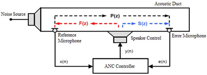
Where is the reference signal of the controller, is the controller output signal, the error signal, the transfer function between the noise source and the microphone error (primary path), is the transfer function between the actuator and the error microphone (secondary path) and is the transfer function between the actuator and the reference microphone (feedback path).
As shown in this configuration, the reference microphone picks up unwanted signal at a later point the noise source, and generates , before this signal passes through the actuator. This signal is processed by the ANC controller, which in turn generates a control signal of equal amplitude and opposite phase of the incident signal, to the actuator. Where the signal , anti-noise, is used by the actuator to produce a canceling sound that attenuates the primary acoustic noise in the duct. The error microphone generates a signal used to monitor controller performance.
The basic principle of feedforward control system is that the propagation delay of the sound wave between the reference microphone and speaker, offers sufficient time to calculate the control and activate the anti-noise, thus causing the cancellation. So that the distance between the reference microphone and canceling speaker satisfies the principle of causality.
The main goal of the feedforward controller is to anticipate the physical phenomenon in a predictive way through the information captured by the reference sensor, so that the noise was canceled when going through error sensor.
2.2. Algorithm of adaptive filtering
Sensors and actuators are administered through an electronic unit (controller) designed for cancellation of unwanted noise in the plant, which is based on the principle of wave superposition. It mostly consists of generating an anti-noise same amplitude and opposite phase to the unwanted noise in order to cause the cancellation of the noisy signal at a given point or region of interest [5, 6].
Although conceptually simple, there are several difficulties to be overcome when installing this type of controller. Significant variations in environmental conditions and non-linearity of the sensors and actuators can hamper and even compromise the controller’s efficiency because introduce unwanted disturbances in the system [7] and change the algorithms of the transfer functions.
In an attempt to counteract these disturbances and alterations, the researchers developed the automatically adaptive controllers. These are inserted in adaptive filters in digital signal processors (DSPs) that promote, through adjustment of its coefficients, the noise reduction system [8, 9]. For this procedure, the filter normally used is the type Finite Impulse Response (FIR) and the mechanism normally used in the setting of the filter coefficients are versions of variants LMS (Least Mean Square) classic. In this case was used the LMS algorithm along with FxLMS algorithm.
The active noise control reached a stage of development such that commercial systems are now available in major practical applications [10].
3. Microphones
The microphones are critical components to identify the noise. Because they are one electroacoustic transducer, they are responsible for transforming sound waves into electrical signals. This enables the handling and processing of these signals by means of electronic components, and can thus amplify, filter and store these signals.
There are several types of microphone, with different principles of operation. Existing principles are: varied contact resistance, electrodynamic, piezoelectric and electrostatic. However, all microphones are based on the conversion of a mechanical wave in a proportional electrical signal to this.
Each microphone has certain characteristics that are specific to certain types of applications. According to Gerges [11], these characteristics are: frequency response curve, dynamic range, directivity and sensitivity.
The microphones studied in this work are of the electrostatic type, being three different condenser: Bruel & Kjaer type 4957, PCB 130E22 and SAMSON C02; and an electret microphone: JL- 061C.
4. Duct project
For the verification of low cost microphones, applied to the ANC, it was necessary the construction of a duct without high costs and complex geometries using easily accessible and inexpensive materials, it was decided to build the duct with PVC pipes.
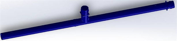
It was designed so a duct 3.8 m in length with a diameter of 150 mm. The primary source was positioned at one end to 1.735 m speaker of cancellation. In Fig. 3 shows the isometric view of the assembly of the duct, made in CAD software to design 2D and 3D.
Fig. 33D CAD design of the duct
In a uniform circular cross-section duct diameter , considering the propagation environments cylindrical, the lower cutoff frequency () corresponding is given by [12]:
Therefore, this duct is flat acoustic waves to 672 Hz cutoff frequency, based on calculations of Eq. (1).
5. Instrumentation and technical specification
Four microphones of different specifications were used, a type of speaker and a DSP board.
The speakers used in this experimental procedure is the line Subwoofer Bass UBL Selenium. Model 6MB17A with a diameter of 6 inches, maximum power of 70 Watts RMS and frequency response range of 72-4000 Hz.
They were used for the analysis and comparison of results, to thereby obtain the objective of the proposed work, three microphones each manufacturer. It is one as a reference microphone and two as error microphones. Different microphones previously determined, had as criteria the best frequency response and lower cost compared to expensive microphone.
In Table 1 below proves the criteria used to determine the microphones used in this work, based on the low cost and the best frequency response in a frequency range close to . Below, you can see the price list of the microphones.
Table 1Market price of microphones
Microphone | Market price (US$) |
JL-061C | 0,30 |
Samson – C02 | 120,00 |
PCB Piezotronics – 130E22 | 600,00 |
Brüel & Kjær – 4957 | 1000,00 |
Since this work aims to better economic viability on an ANC system, sensors and actuators are less accurate and inexpensive. However, because the added capability of digital signal processing in DSK C6713 platform the response obtained had the same success that a system using components with higher added value.
The DSK 6713 Board Spectrum has the following characteristics:
• DSP Texas Instruments TMS320C6713;
• RAM memory of 16 MB (megabytes);
• Analog inputs: MIC IN and LINE IN;
• Analog outputs: HP OUT and LINE OUT.
6. Experimental procedures and results
6.1. Experimental procedure I – characterization of the microphone in the frequency domain
Characterize the frequency response curve of the microphones allows us to know the frequency range that each microphone works with more efficiency. For this, a methodology aimed at identifying and comparing the values obtained in decibels for each predetermined frequency has been prepared. The proposal is to sweep the entire range of frequency of the microphones, with emphasis on frequencies up to 500 Hz.
Using a calculation program the value of the reference sound pressure, so that the microphone PCB having, is 0.16896. This value is used to calculate the SPL () of the other pre-set frequencies for all microphones in Eq. (2):
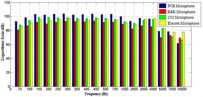
After the treatment all signs acquired in the measurements was generated Fig. 4.
Note that, as mentioned earlier, that the microphone to the PCB SPL frequency of 1000 Hz is equal to 100 dB. This enables comparison of different types of microphones studied, as reference in all other values to a single value. With it, you can see the sensitivity of each microphone, identifying the most sensitive microphone is the microphone PCB and less sensitive microphone is the microphone Bruel & Kjaer.
Another feature that should be highlighted is the stabilization of values of the NSP for all microphones in the frequency range 150-500 Hz, with a variation of 2 dB for PCB and Samson microphones, but the microphones electret and Bruel & Kajaer undergo a somewhat greater variation being 3 dB and 4 dB, respectively.
The analysis of the data shown in Fig. 4 concludes that all microphones can be used in an active noise control system.
Fig. 4SPL to the microphones in a study using the reference sound pressure P0
6.2. Experimental procedure I – application of ANC
The evaluation of the microphones in the application of ANC aims to identify which of the microphones have better performance for this type of application.
The main parameter to be analyzed in this experiment was the attenuation obtained by applying the ANC. This was done using a sound pressure meter calibrated.
As the variable under consideration is the attenuation that the ANC causes and this calculation is performed by SPL difference before and after application of the ANC, was standardized as would be the measurements performed with the sound pressure meter. Set the position of this unit as the end of the duct, directing your microphone into the duct. Two measurements were made, prior to application of the ANC and the other measuring after application and the stabilization of the ANC. Each measurement time is 2 minutes and the results are presented in the discussion below.
The last point to be made is that the background noise in the room where was installed the product about 50 dB at the time of measurement.
The Table 2 below shows the overall SPL obtained at each measurement, making the difference between the values obtained before and after applying the ANC and with this result the column labeled attenuation.
Table 2Attenuation of global SPL
Microphone | SPL before of the ANC (dB) | SPL after of the ANC (dB) | Attenuation (dB) |
PCB | 88,7 | 51,9 | 36,8 |
Bruel & Kjaer | 88,7 | 50,6 | 38,1 |
Samson | 88,9 | 51,6 | 37,3 |
Eletreto | 89,2 | 49,4 | 39,8 |
Observing the results, we note that all the microphones were able to mitigate the noise generated significantly, reaching levels close or equal to the background noise. Through the comparisons made by graphic confirms the decline in the SPL in octave band whose center frequency is 250 Hz, regardless of microphone used. This directly influences the results presented in Table 2, because the value of the global SPL depends on the value of the SPL presented in each band.
7. Conclusions
This study compares the performance of high and low cost microphones in a ANC system. Two microphones considered high cost were studied, Bruel & Kjaer and PCB. The microphones low cost are Samson and electret. Both microphones can be applied in the ANC to the standard conditions in this work. All microphones have similar performance. The cost benefit of using low cost microphones compared to the other is much greater. To achieve the same attenuation level, the invested monetary value is significantly lower. Comparing prices from Bruel & Kjaer microphone with electret microphone, this value can reach the order of 0.05 %.
• All microphones studied in this work are able to be applied in ANC in circular ducts with a diameter of 150 mm, where the noise source to generate a tonal signal 250 Hz;
• All microphones obtained attenuation next to the SPL of background noise, this suggests that background noise could have influenced the results obtained;
• The method used to characterize the microphones, by means of tonal signals, guaranteed way to make a comparison between these sensors. However, it is important to stress that there are several cascade systems in the experiment, such as: microphone, preamp, computer audio card, cables, among others.
References
-
Bistafa S. R. Acústica Aplicada ao Controle de Ruído. 2nd Edition. Editora Edgar Blucher Ltd., São Paulo, 2011, (in Spanish).
-
Riyanto B. Real-time DSP implementation of active noise control for broadband noise using adaptive LMS filter algorithm. International Conference on Electrical Engineering and Informatics, 2007, p. 718-722.
-
Minguez A. Inginieria Avanzada Para Sistemas De Controle De Ruido Acústico Mediante Técnicas Adaptativas. Doctoral Thesis, Universidade Politécnica de Madrid, 1998, (in Spanish).
-
WidrowB.,Stearns S. D. Adaptive Signal Processing. Prentice-Hall, Englewood Cliffs, NJ, 1985.
-
Nelson P. A., Curtis A. R. D., Elliott S. J., Bullmore A. J. The minimum power output of free field point sources and the active control of sound. Journal of Sound and Vibration, Vol. 116, Issue 1, 1987, p. 397-414.
-
Hansen C. H.,Snyder S. D. Active Control of Noise and Vibration. E&FN Spon, London, U.K., 1997.
-
Kuo S. M., Morgan D. R. Active noise control: a tutorial review. Proceedings of IEEE International Symposium on Circuits and Systems, 1999, p. 943-973.
-
Goodwin G. C., Sin K. S. Adaptive Filtering Prediction and Control. Prentice-Hall, Englewood Cliffs, NJ, 1984.
-
Clarkson P. M. Optimal and Adaptive Signal Processing. CRC Press, Boca Raton, FL, 1993.
-
Qiu X., Lu J., Pan J. A New Era for Applications of Active Noise Control. Inter Noise, Melbourne, Austrália, 2014.
-
Gerges S. N. Y. Ruído Fundamentos e Controle. 2nd Edition. NR Editora, Florianópolis, 2000, (in Spanish).
-
Delfino L. C. Controle Ativo de Ruído em Dutos Utilizando Processador Digitais de Sinais. Federal University of Uberlândia, Uberlândia, MG, 2005, (in Spanish).
About this article
