Abstract
A review on investigations of precise vibromechanics and vibroengineering performed in Lithuania is presented in this paper. Results of research, inventions and innovations obtained in this field are discussed. Some of the development in the area of precise vibromechanics are presented in more details.
1. Research in the field of vibroengineering
The start of research activities in vibroengineering was in the Lithuanian Academy of Sciences in the year 1954, later it was transferred to Kaunas Polytechnic Institute in the year 1963 and developed to the research center “Vibrotechnika”. A new scientific direction was created, the so called precise vibromechanics and vibroengineering.
Research associates working in the field of vibroengineering visited leading scientific research institutes, experimental construction bureaus all over the USSR. The purpose was to ensure financing for work of scientific creative character. It was possible to propose our own ideas, based on vibrations and waves that were useful for the designed devices and objects. Some of the proposed research work may be used for future technologies after a number of years.
The created scientific field of precise vibromechanics and vibroengineering is applied in all areas (industry, space technology, medicine, biology, art). In this scientific field directions of stabilization, robotization, control was created, that are based on vibrations, waves, nonlinear effects and qualities of dynamical systems.
More important development created in “Vibrotechnika” are described in details.
Principles of effects:
• the effect of combined dynamical synchronization and original methods and means of implementation were created;
• the effect of dynamical directivity of systems of definite types was created. Because of vibrations laws of motions of self-organizing systems, trajectories or unstable and stable dynamical structures of systems are created. On this basis new technologies were created. For example, when vibrating liquid polymers in the process of their transition to solid status the dipoles are oriented, this enables to make the electrical resistance of the polymer in different directions to differ more than one thousand times;
• systems with variable degrees of freedom were created. They were implemented in contact devices consisting from two elastic elements mutually contacting by impacts: when their eigenfrequencies coincide both elements connect together at the contact point and move together in a definite region of parameters, or during a single impact there are no multiple contacts;
• some devices based on transverse standing waves were created:
- valves and fluid dosing devices, consisting of tube filled with liquid with balls freely located inside those tubes. The longitudinal motion of the balls in the tube is limited by supports. When the tube is excited by transverse vibrations the balls try to locate themselves to the nodal points or points corresponding to maximum amplitudes of vibrations;
- device for separation of multiphase flowing liquids into separate parts;
• cleaning of the surface of a rotating cylinder from waste material using travelling waves excited in air was implemented.
Principles of change of motions:
• several new principles based on vibrations and waves of bodies were created by using nonlinear effects with the purpose of forcing the bodies to move according to the desired laws and trajectories or to perform positioning in space with high precision. Based on those principles many vibration drives and vibration motors were created;
• dynamical systems without kinematic connections were created that change rotational and translational motions one into another;
• for the implementation of very small displacements devices based on capillary principle and vibrations were created;
• in order to perform small displacements systems based on deformations of definite shapes of rigid deformable bodies were created.
Principles of stabilization:
• for the stabilization of moving systems principles based on high frequency micro vibrations and travelling waves were created;
• vibration protection methods and means self-regulating according to the force fields were created;
• for the change of static centering of rotor systems effective vibration methods and means of dynamical centering were created;
• the identification and stabilization of rigid bodies rotating about any axis is ensured by the created method, based on the investigation of their dynamics about three orthogonal axes;
• automatic dynamical isolation of vibrating systems with several degrees of freedom was implemented that protects the environment from vibrations;
• active protection of human hearing organs from external noises was implemented;
• methods and means to accept external signals by technical devices and to transfer them to the brain through the vibrations of human skin instead of eyes and ears were created.
Principles of change of energy:
• methods and means to transform mechanical energy of rigid bodies or flows into electrical by auto-vibrations or auto-waves were created;
• ecological motors and vibration devices based on energy accumulated by constant magnets were created;
• thermal motors based on materials with the so called memory were created;
• effective dynamical transformation of mechanical energy between rotational and translational motions was implemented;
• systems for fast focusing of optical energy in space were created.
Principles of control:
• methods and means of precise measurement of vibrations which eliminate disturbances were created;
• methods and means of measurement of displacements and their derivatives based on surface waves were implemented;
• also methods of measurement of displacements and their derivatives based on photo-stroboscopic process were created;
• optical methods for measurement of displacements in the level of nano dimensions were created;
• powerful acoustic vibrators with controlled spectrums for testing, or diagnostics, or destruction of objects and buildings were created.
Those and other facts revealed during the investigations, methods and means created on their basis, a number of inventions and innovations were and are effectively revolutionary used in science and engineering. Operation of some of the created objects looks as paradox phenomena.
Contemporary investigations were also performed:
• division of rigid bodies into molecules;
• essence of differences of creation of sound forms created by a separate singer and chorus;
• a platform for cleaning of lungs by exciting controlled waves in the lungs was created;
• controlled vibration of air inhaled into the lungs according to the desirable parameters;
• device for measurement of air debit in the process of breathing;
• a platform on which for a tired human being during several minutes tiredness is eliminated was created that is some of the human parameters (pulse, blood pressure) are restored to those which were before the hard work;
• method and means to diagnose some nerve and heart diseases according to the vibration characteristics of human muscles were created;
• means for transportation of materials by waves in channels of biological systems were created;
• the processes of any nature registered by technical devices may be transferred to the brain through forced external vibrations of human skin. The brain reacts by signs of various colors depending on frequencies and characteristics of vibrations.
More than half of a hundred of monographs and books were prepared and published, more than 1000 scientific research papers, more than 2500 inventions and patents, more than 300 doctoral and habilitated doctor dissertations were defended, 69 editions of scientific research works were published, 22 books of innovations were published, series of books on vibration engineering was published. Kaunas branch of the Seminar of Theory of Mechanisms and Machines of the Academy of Sciences of the USSR was taking place in the time period 1963 – 1990 years. Every year several expanded seminars were organized. Scientific Center “Vibrotechnika” published papers of the Seminars. Now there are 6 members of Lithuanian Academy of Sciences, which originated from “Vibrotechnika”.
After the decay of the socialist camp and transformation to new state orders, in the time period of 1990-1995 years scientific research in the former USSR and Eastern Europe (including Lithuania) decreased substantially. Kaunas Polytechnic Institute became Kaunas University of Technology. Scientific center “Vibrotechnika” was destroyed in Kaunas University of Technology.
About half of a hundred of scientists having the degrees of habilitated doctor, professors and a number of doctors of science were employed in various departments and laboratories. A number of scientists managed to transfer to creative activities in other domains: more than 30 scientists became heads of private enterprises of creative profile. About 30 scientists are working abroad (USA, Bulgaria, Armenia, Ukraine, Moldova, Romania, Israel, Uzbekistan, Tajikistan).
Now in Lithuania investigations of mechanical, biomechanical systems under the action of various vibrating physical, among them mechanical (such as accelerations, velocities, forces, temperatures), optical, gravitational, electromagnetic and other, processes and fields are performed.
Lithuanian scientists take part in the investigations of the influence of vibrations of the magnetic field to the human organism and also in the investigations of the vibrations and waves of brains which are performed in the USA. Here especially actively participate physicians of the Lithuanian University of Health Sciences and specialists of technical sciences and mathematics of Kaunas University of Technology. The below presented work is the example of synchronization of mechanical systems.
2. Self-synchronization of pneumatic exciters of vibrations on air cushion
2.1. Introduction
This scientific paper is closely related with previous researches in this area that were described by L. Licht and others that have investigated the self-exciting vibrations occurring in air bearings [1].
Ragulskis K., Galinskas A., Šermukšnis A., Kibirkštis E. [2-5] and others created various one dimensional and two dimensional vibroexciters based on air cushion and accumulators and created basis of their theory. Spruogis B., Ragulskis K., Bogdevičius M., Matuliauskas A., Mištinas V., Kibirkštis E., Pauliukaitis D. [6-8] developed transformation of vibrations of mechanical systems to step and continuous motions of single direction on the basis of pneumatic exciters of vibrations. This is used for the creation of robots. Gecevičius J., Ragulskis K. [9] and others created a vibrating platform with three directions based on two unbalanced pneumatic exciters of vibrations of rotor type. For the latter two exciters of vibrations they proposed to introduce a self-vibrating contour and created a simplified theory of synchronization of those vibroexciters.
In this investigation the systems have been created, which because of self-vibrations may synchronize the operation of exciters of vibrations and control the phase difference of their vibrations. More precise theory was created, which is confirmed by experiments. Regions of existence of synchronous regimes and their transition to chaotic vibrations have been analysed.
2.2. The model of the system
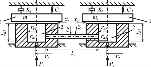
Research of self-synchronization of two vibroexciters connected with pneumatic channel in the shape of a tube (radius , length ) is carried out in this work. Principal scheme of the analyzed mechanical system is shown in Fig. 1.
Fig. 1Scheme of self-synchronization of pneumatic vibroexciters: 1 – oscillatory mass, 2 – chamber of vibrodrive, 3 – tube link, P1, P2 – supplied gas pressure, r1, r2 – radius of the air supply channel, rk1, rk2 – chamber radius, lk1, lk2 – chamber height, ra1, ra2 – external radius, lv – length of the linking channel, rv – radius of the linking channel
A simplified model of gas flow is used for creating a mathematical model. The system is described by two differential equations of second order that describe the movement of working body (masses m1 and m2) of each vibroexciter:
where and – initial tightening of vibrating masses and that cause the rigidity of the whole system, and – pressure of pressed air in the chambers, – atmospheric pressure ( = 101325 Pa), , – coefficients of resistance, , – coefficients of rigidity, and amplitudes of vibrations of chambers of working body.
The mass of gases in the chambers is described by the law of gas mass balance:
where , when , , when ;
where , when , , when .
Here and – mass of gas in the chambers, and – amount of feeding air, and – amount of air flowing out from the chamber in the direction of the working body, – amount of gases flowing out (feeding in) from the chamber through the synchronization channel. In general, the mass of gases in the chambers is calculated as:
Defining the flow of gases inside the chamber it is assumed that the process is adiabatic and the density of gases and the pressure do not depend on coordinate. According to the theory of thermodynamics the main parameters (pressure , density temperature ) of gas state are linked by the equation:
where – volume of gas, – mass of gas, – molar mass of gas, – universal gas constant ( = 8.314 J/mol K). Considering that and (J/kg K) – gas constant depending on gas type, Eq. (6) could be expressed:
The pressure and density during adiabatic process are linked by the formula:
The velocity of gas flow increases up to the level of critical sound velocity with the decreasing of value of the ratio . The critical pressure ratio from the energy equation could be expressed as:
where – ratio of critical pressures ( = 0.528); = 1.405; – coefficient of thermal conductivity under constant pressure; – coefficient of thermal conductivity under constant volume.
Evaluating Eq. (7-9) and applying De Saint Venant and Vantzel equations, gas stream that enters the chambers ( = 1, 2) and stream flowing out from the chambers for the present system could be expressed by the equations:
where – coefficients assessing the gas resistance: – resistance coefficient of air entering into the chamber; – resistance coefficient of air flow from the chamber; – density of supplied air.
The gases do not transfer the heat with the walls of synchronization channel when its length is small. The losses of pressure due to friction along the tube that has length of the segment according to Darcy is expressed as:
where – coefficient for evaluation of friction and other technical losses, – velocity of gas flow, – diameter of the tube.
Applying the equation of energy, the differential equation of kinetic and potential energies could be created evaluating the losses in the interval :
According to the equation of ideal gases and from the balance equation: , then the velocity is:
where – amount of entering and flowing gases, – cross-section area of the tube. Inserting Eq. (14) in Eq. (13) it is obtained:
If the pressure at the beginning cross-section of the tube is and at the end – and the length of the tube is , the equation is obtained:
Expressing from Eq. (15), an equation of gas amount in case of isothermal flow in the tube is obtained:
According to the notations in Fig. 1, the change of amount of gas in 1 s in the synchronization tube of pneumatic vibroexciters could be written as follows:
Thus the dynamics of two vibroexciters connected with synchronization tube could be described by the system of Eq. (1-4), where expressions from Eq. (10, 11) and Eq. (18) are used.
The differential equations are described in matrix form – Eq. (19), where the changing members with respect to time at each time moment are recalculated in different procedures:
where the expressions of functions and are solved from Eq. (1) and Eq. (2) respectively and the functions and are deduced from Eq. (3-5), Eq. (10, 11) and Eq. (18).
2.3. Analysis of results of calculations
During the investigation the geometrical parameters (, , , , , ) of chambers, also pressures and that enter into the chambers, masses m1 and m2 of the working body were changed. At the beginning the vibrations without the tube connection of working bodies of vibroexciters were tested, i.e., vibroexciters were working independently (without synchronization channel). Later the influence to character of vibrations of introduction of the synchronization channel between the vibroexciters was analyzed. The data of synchronization channel in all samples were constant: length = 100×10-3 m, radius of tube = 2.5×10⁻³ m.
Fig. 2Vibrations of both working bodies of vibroexciters with synchronization channel: a) vibrations in the interval of 1 s, b) phase view of vibrations
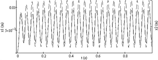
a)
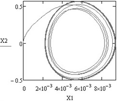
b)
Fig. 3Vibrations of both working bodies of vibroexciters with synchronization channel: a) vibrations in the interval of 1 s, b) phase view of vibrations
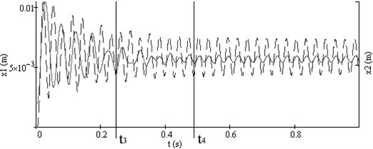
a)
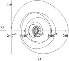
b)
Typical synchronous regimes of operation of the investigated system are presented in Fig. 2 and Fig. 3.
3. Conclusions
Self-synchronization by connection tube was proposed for two pneumatic vibroexciters on air-cushion. The mathematical model of investigated mechanical system was made and testing results of this equation system were obtained. Simplified model of gas flow was used for making the mathematical model.
It was determined that the self-vibrations of one phase were obtained in both vibroexciters by choosing particular geometrical parameters of vibroexciters and the initial conditions for vibrations and introducing the synchronization channel. It was obtained that the character of law of motion as the working body begins to vibrate in the regime of self-vibrations could be of various different types.
The results of calculations show that the amplitudes of self-vibrations commonly decrease, but in some of the cases the amplitude in one vibroexciter increases and in the other decreases after introduction of the synchronization channel.
Numerical analysis has shown that after introducing of synchronization it is possible to choose such parameters of the mechanical system, which enable to obtain harmonic vibrations in both vibroexciters or in one of them to form non-harmonic law of motion of the working body as both vibroexciters previously have been operating in different vibrations regimes.
References
-
Licht L., Fuller D. D., Sternlicht B. Self-excited vibrations of an air-lubricated thrust bearings. Transactions of ASME, Vol. 80, 1958, p. 411-416.
-
Galinskas A. V., Ragulskis K. M., Šermukšnis A. P. Use of the Phenomena of “Pneumatic Hammer” to Generate Directed Vibrations. Problems of Development of Gas Lubrication. Part 2. Report at the Union Coordination Meeting, Science, Moscow, 1972, p. 238-247, (in Russian).
-
Šermukšnis A. Questions of Dynamics of Pneumatic Generators of Vibrations. Thesis of Doctoral Dissertation, Kaunas Polytechnic Institute, Kaunas, 1969, (in Russian).
-
Kibirkštis E. Development and Investigation of Pneumatic Vibration Exciters of Self Vibrating Type. Thesis of Doctoral dissertation, Kaunas Polytechnic Institute, Kaunas, 1980, (in Russian).
-
Kibirkštis E. Development and Investigation of Multifunctional Pneumatic Transducers Working in the Mode of Self-Exciting Oscillations. Theory and Application. Abstract of the Dissertation of Doctor Hability, Vilnius Technical University, Vilnius, 1993.
-
Spruogis B., Ragulskis K., Bogdevičius M., Ragulskis M., Matuliauskas A., Mištinas V. Robot Performing Stepping Motion Inside the Pipe. Patent LT 4968 B, 2002.
-
Ragulskis K., Bogdevičius M., Mištinas V. Analysis of dynamic processes in self-exciting vibration of an in-pipe robot. Proceedings of the 11th International Conference, Kaunas University of Technology, Kaunas, 2006, p. 274-277.
-
Ragulskis K., Kibirkštis E., Pauliukaitis D. Robot actuator operating as a self-exciting system on air films. Proceedings of the 10th International Conference on New Actuators and 4th International Exhibition on Smart Actuators and Drive Systems, Bremen, Germany, 2006, p. 1041-1044.
-
Gecevičius J., Ragulskis K. Dynamics of Planetary Pneumatic Vibrators. Vibrations of Complex Mechanical Systems, Mintis, Vilnius, 1969, p. 147-193, (in Russian).
-
Gladyshev N. N. Fluid and Gas Dynamics: Compendium for Lectures. Saint-Petersburg state University of Plant Polymers. Saint Petersburg, 2012, p. 5-24, (in Russian).
About this article
