Abstract
In the paper the stress-strain state of hexapod robot is considered in order to clarify its dynamical characteristics. Full-size model of hexapod robot is built in the SolidWorks program complex. The state of the robot was analyzed in an extremely dangerous location at static loading. Dynamic analysis was conducted to clarify oscillation of the support unit in the robot’s construction. The results of the survey show that such robot design cannot be used in the environments with the vibrating background below 5 Hz.
1. Introduction
In the process of operation of the robot-hexapod performing a process task it is necessary to assess static and dynamic characteristics, and identify the behavior of the system as a whole. Given the fact that the analysis of different calculation schemes need to select the best, you should spend a large amount of numerical calculations, it is therefore necessary to resort to the use of computers.
The calculation was made in CAD system SolidWorks. For analysis in the software package SolidWorks was built full-size simplified model of the robot hexapod, shown in Fig. 1. When solving problems of structural analysis required to solve the following computational procedure:
1. Static analysis (determination of the static stresses, strains, displacements, assessment of strength)
2. Dynamic analysis (determination of free oscillations of the system under the action of external forces frequency methods).
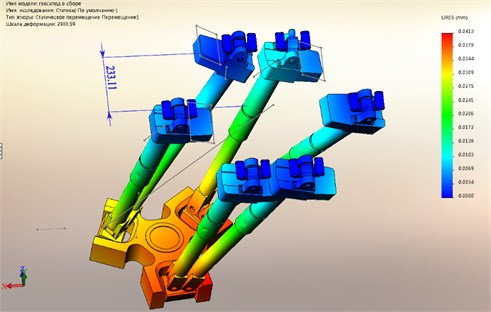
Fig. 1Motion under static loading
2. Static analysis
The main goal of static analysis is to determine the percentage error of the position of the platform under static loading in an extreme dangerous situation in comparison with positioning accuracy stated in the passport equipment – 0.1 mm.
Technical characteristics of the equipment provided the maximum payload of the robot is 100 kg in the simulation of the process of loading were also taken into account the mass of the hexapod – 200 kg model of the robot was moved to the end position (an extreme we assume a position in which the platform is at a maximum distance from the axis of symmetry in the initial position, when all the rods have the same length). For the calculation will apply the load to the platform maximum load capacity hexapod, and take into account its own weight. We assume that most vulnerable spot is the hinge joint that takes the maximum load, so will do the rods absolutely rigid.
Created computational model of the robot Fig. 1 has ball screw (ballscrew) and gear. Their presence is accounted for by the rotation in the hinge bearings (ball screw stops the spontaneous movement of the rods like a worm mechanism). In mounting the bottom hinges applied conventional bearing components and “pins” (axes), i.e. the platform in these sites is mobile.
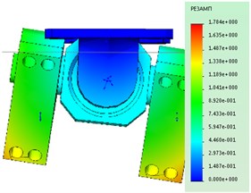
The analysis showed that when the loading platform is displaced to the center of balance within the deformation of the structure by the amount in the range of 40 microns. see Fig. 1, which is 40 % of positioning accuracy. Therefore, when using the robot in industrial environments that require high precision operations, it is necessary to consider not only the positioning error but also the deformation of the nodes of the hexapod during loading.
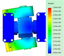
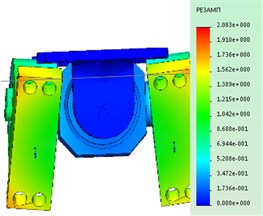
The maximum stress, as seen in Fig. 2, occur in areas of the contact details of reference nodes. The loaded barbell is a rod indicated by the arrow in Fig. 2.
Fig. 2Tension under static loading
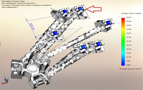
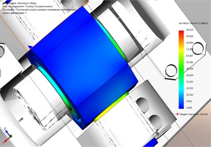
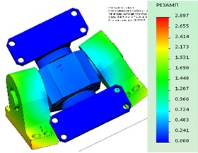
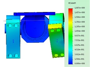
Fig. 3Dangerous subassembly under static loading
3. Dynamic analysis
When analyzing the frequency characteristics of the reference node of the hexapod mounting is not rational to calculate the whole full size model of a hexapod. Such a solution will require large capacities of computing hardware. Accordingly, it is necessary in the calculation of the node to find the module and direction of these forces so that under the action of the load support unit has experienced the stress-deformation state in the same power calculation a full-sized design. Since the problem is symmetric, we will construct the calculation model of the reference node, given its stress-strain state in the overall design.
According to the results of maximum stresses are around 100 MPa, see Fig. 3 in the contact area, the axis of the hub and the bearing ring (the magnitude of the stresses varies within ±10 MPa, it all depends on the accuracy of the mesh elements).
Parts indicated by the arrows, see Fig. 4, is not subject to special stress, therefore, will consider them as absolutely rigid, as in the initial calculation, meaning that the entire burden assumes hinge joint.
Fig. 4Stress-strain model
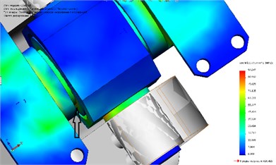
Fig. 5Finite element model
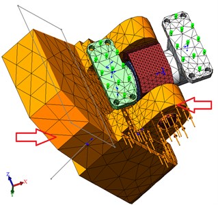
Fig. 6The shapes of the reference node at various frequencies: a) Form of oscillations at the frequency of 1907 Hz, b) Form of oscillations at the frequency 2934 Hz, c) mode Shape at a frequency of 3417 Hz, d) mode Shape at a frequency 3557 Hz, e) Form at a frequency of 4488 Hz
a)
b)
e)
c)
d)
Make a load of 10 000 N on the end of the element bracket to obtain the necessary stress-strain state, see Fig. 5. Because the element is absolutely rigid, it is not prone to deformation and transmit the load on the fastening elements.
Get the stress-strain state of the reference node, see Fig. 4. The maximum stresses happened in the area of 96 MPa and a maximum is observed in the area of contact of the bearing ring and the axis (arrow) and in the transition cervical cross the wall.
The resulting model can now be used in the frequency analysis. This type of analysis allows to identify forms its own harmonic vibrations that occur when loading products. The calculation was 5 identified mode shapes and resonant frequencies for each of them.
4. Conclusions
Each form of the oscillations matches the card resonant amplitudes. The obtained data show that to exploit the structure of the robot is prohibited in an industrial environment, vibration is below 5 Hz, due to the fact that the system is able to enter in resonance and break. Also the design of the robot might get damages in the process of low-frequency or seismic activity in hazardous industrial areas.
References
-
Sagdeev Y. A., Kopysov S. P., Novikov A. K. Introduction to finite element method. Publishing House “Udmurt University”, Izhevsk, 2011, (in Russian).
-
Gaponenko E. V., Rybak L. A., Chichvarin A. V. Determination of static error of the machine with parallel kinematic. World Applied Sciences Journal, Vol. 30, Issue 9, 2014, p. 1193-1198, (in Russian).
-
Rombach G. A. Finite Element Design of Concrete Structures: Practical Problems and Their Solutions. Thomas Telford Publishing, London, 2004.
-
Solin P. Partial Differential Equations and the Finite Element Method. Wiley-Interscience, New Jersey, 2005.
-
Hughes Thomas J. R. The Finite Element Method: Linear Static and Dynamic Finite Element Analysis. Dover Publications, New York, 2000.
-
Magergut V. Z., Ignatenko V. A., Bazhanov A. G., Shaptala V. G. Approaches to construction of discrete models of continuous technological processes for synthesis control machines. The Bulletin of BSTU named after V. G. Shukhov, Vol. 2, 2013, p. 100-102, (in Russian).
About this article
This work supported by the Russian Science Foundation, the Agreement No. 16-10-00148.
