Abstract
The paper covers the questions of modeling and research different hydrodynamic effects, that influence the occurrence of lateral vibrations in rotor systems with fluid-film bearings. The present research is aimed at developing rotor dynamics as one of the fields of science, as well as at developing the analysis and diagnostics methods of the dynamic condition of the rotor systems with fluid-film bearings. The results of the present research consist of a complex of the developed mathematical models and the numerical methods of solutions for centering and Magnus effects in fluid-film bearing and its influence on dynamics of rotor system. The significance of the results is determined by a wide range of applications in various designs of single-shaft rotor systems. The novelty of the obtained results is in the developed mathematical models that allow solving the analysis problems of lateral vibrations in the rotor systems with fluid-film bearings, given a nonlinear formulation of the problem; which significantly broadens the spectrum of the analyzed parameters domain.
1. Introduction
The rotor with fluid film bearings is active-dissipative system in which the complex of hydrodynamic and heat transfer processes, and also different types of axial and lateral vibrations is realized. Viscosity, surface wettability, compressibility, phase transitions, turbulence, multiphase, rheological properties, technology factors, thermal, elastic, inertial processes acting important role for load-carrying capability of a fluid film. In the hydrodynamic lubrication theory, depending on importance of the phenomena mark out thermal hydrodynamic, elasto-hydrodynamic, thermal elasto-hydrodynamic also multiphase and hybrid lubrication with different types of friction. However today there are no works on influence on dynamics of a rotor of such effects in bearings of liquid friction as, Magnus effect and the aligning effect at axial giving (Lomakin effect).
2. Main text
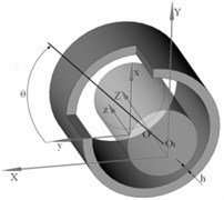
Main complexity of rotor-bearing modeling is calculation of fluid film bearing reaction (Fig. 1). Fluid film bearing design model represented Fig. 1.
The majority of works by calculation of fluid film bearing reaction is based on the solution of the Reynolds Eq. (1). And here, determination of the pressure distribution is a complex boundary problem based on the Reynolds equation. Using the operators of the partial first derivatives in the forms of and , this equation reads:
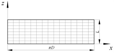
where and are the circumferential and axial coordinates of bearing’s sweep, respectively; represents the pressure inside the bearing; and are the viscosity and density of the fluid accordingly; is the radial gap function; and are the turbulence coefficients in the directions of turbulence, namely in the and directions, correspondingly, that determine the effective viscosity when the flow is turbulent considering the Reynolds stress. In expression Eq. (1), and are the values of the circumferential and radial velocities of the surface points of the shaft. The form of Eq. (1) is not exclusive and can vary depending on the different types and operational conditions of the bearing, more detail on the forms of Eq. (1) can be found in [1-4]. However, there are works [5, 6] in which modeling is based on solution Navier-Stokes equation (NS equation).
In present paper the bearing with the following geometric and operating parameters is investigated: 50 mm; 50 mm; 100 µm; 10-3 Pa·s; 1000 kg/m3, where and are diameter and length of bearing, respectively; is the radial clearance.
Fig. 1Fluid film bearing design model
2.1. Magnus effect
During the operation of the radial fluid film bearing there is a situation which can lead to emergence of effect of Magnus, a mathematical problem definition, system of the of continuity and Navier-Stokes equations in cylindrical system of coordinates, which solutions of boundary conditions:
1) Known pressure at bearing ends:
2) Known velocity on shaft surface:
where and – functions of on shaft surface velocity component and respectively; – shaft radius.
3) Zero velocity “wall” on bearing surface:
where .
Values of functions and on shaft surface can be derived by relationships:
where – rotor angular velocity; and – component and respectively of shaft center velocity.
Reactions of fluid film bearing can be derived by derived by relationships:
where – shear stress on shaft surface.
For the analysis of a possibility of the accounting of Magnus effect two approaches for calculation of fluid film hydrodynamic reactions have been used: 1) on the basis of the solution of the Reynolds equation by finite elements method with a mesh 40×40 of elements; 2) on the basis of the solution of the Navier-Stokes equation in the Ansys CFX by finite volumes method with a grid of 50 elements on bearing length, 400 elements in the circumferential direction of the bearing and 20 elements on thickness of a fluid film.
Calculations were carried out for the concentric position of a shaft and at equality to zero in the Eq. (5). During the carrying out calculations and representation of results the following dimensionless parameter has been entered:
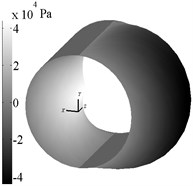
Typical pressure profile is presented in Fig. 2 when calculating of the described problem.
Fig. 2 shows cylindrical surface of sleeve fluid-film bearing, which is used as the base surface for pressure field in a cylindrical frame. Note that when calculating negative area of the field of pressure not set to zero as it usually becomes when calculating bearings of sliding, it is made for convenience of comparisons of the importance of fluid film reactions.
Fig. 2Typical pressure profile for Magnus effect (ω= 500 rad/s, VX= 2,49 m/s)
2.2. Lomakin effect
The theoretical analysis of radial forces in ring gaps, is successfully executed by Lomakin [7] who has offered a physical explanation for an origin of the radial hydrostatic aligning force in a ring eccentric gap and has removed a formula for its calculation. Further researches of this for clearance seals consolidations can be found in works [4, 8].
However, in all works of this effect were investigated namely the noncontact seals in which opposed bearing mainly lubricant axial flow, and which have a small axial size in comparison with the bearing.
In this work the technique of accounting of this effect through entering of nonlinear boundary conditions in Reynolds equation is offered Eq. (1).
At an entrance end face of the bearing there is a hydraulic pressure drop for sharp edges can be determined by follow relation [9]:
where – entrance pressure; – function of average axial velocities at an entrance end face of the bearing.
Using relationship of a mass flow and pressure gradient on the bearing entrance we will finally receive:
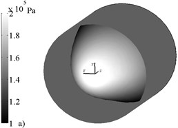
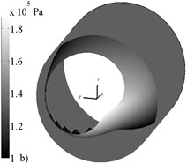
Note that the Eq. (10) is analog of a boundary condition in the form of heat radiation for the heat conductivity equation [10] which provides the steady numerical decision in an iterative method of Newton for a finite element system, it should be noted that in iterative procedure in the right member of Eq. (10) emergence of complex values therefore it is necessary to watch is possible that expression under the radical was positive, otherwise it is necessary set to zero nodal values of additional vectors and matrices. In Fig. 3 typical pressure profiles with and without accounting Lomakin effect are presented.
Fig. 3 shows pressure field like Fig. 2 and demonstrates that accounting Lomakin effect changes the pressure distribution on sleeve surface, that affects the bearing reaction, as consider follow.
Fig. 3Typical pressure profiles for lubricant supply without a) and with b) accounting Lomakin effect (ω= 314,16 rad/s, e= 0,4, p|z=0= 2∙105 Pa, p|z=L= 1∙105 Pa)
2.3. Dynamic model of rigid symmetric rotor
The movement of the geometrical center of a rigid symmetric rotor, can be presented in stationary frame which rigidly connected with the geometrical center of bearing bush by following system of ordinary differential equations:
where – mass of rotor; and – acceleration components of rotor center; and – external rotor forces components.
3. Results
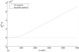
In Fig. 4 results of calculation of reactions of the bearing at the concentric provision of a shaft at change of the dimensionless parameter in range from 0.001 to 2 are presented. Apparently from schedules Fig. 4(b) with growth of angular speed of rotation of a rotor carrying power in the direction perpendicular speeds of the center of a pin increases and to become rather powerful in comparison with force of lobe resistance in Fig. 4(a) that allows to manifestation of Magnus effect.
Also it should be noted that forces of lobe resistance rather good correlate for two accepted models (NS equation and Reynolds equation) that can’t be told about the carrying power which correctly pays off only for NS equation for Reynolds equation she is equal to zero. However, it should be noted that in real rotor units characteristic radial speed makes the size a good assumption of extreme value of characteristic size the increased nominal rate by 5 times is, to this value of characteristic speed of radial speed there corresponds 0.001 value for which in Fig. 5 schedules of components of carrying power depending on the angular speed of rotation of a rotor are submitted.
Fig. 4Fluid film reaction for pressure components: a) X and b) Y
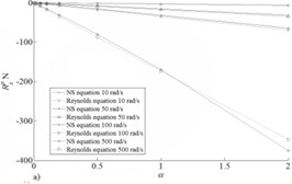
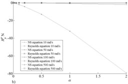
Fig. 5Fluid film reaction (α= 0.001) component Y for pressure a) and for shear stress b)
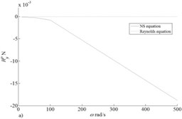
Data for Reynolds Eq. (1) are given in Fig. 4-5 without second composed in his right part of the squeezing film which is responsible for effect as this effect cannot be considered in three-dimensional stationary statement of NS equation what is serious restriction of applicability of this approach for modeling of fluid film bearings. In Fig. 6 dependences of force of front resistance on tangent tension taking into account and without effect of squeezing in model on the basis of Reynolds equation for the parameter is given in range from 0.00001 to 0.001.
Comparing values of reactions in Fig. 4-5 it is possible to draw a conclusion on insignificance of Magnus effect in comparison with friction forces caused by effect of squeezing which usually neglected in practical calculations [2-4].
Fig. 6Fluid film reaction component X for shear stress
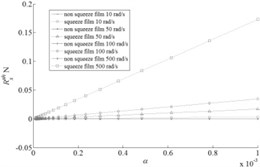
Fig. 7Fluid film reaction for pressure components a) X and b) Y
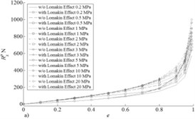
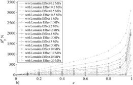
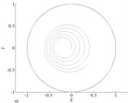
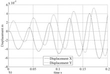
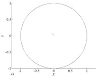
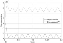
In Fig. 7 results of calculation of reactions of the bearing are presented ( 314 rad/s) depending on the relative vertical shift of the shaft center for various values of pressure at entrance end face of the bearing. Apparently the accounting of Lomakin effect considerably influences a reaction component in the shift direction of the shaft center that does the accounting of this effect important at research of rotor systems supported by fluid film bearings with axial lubricant supply. In Fig. 8 trajectories and lateral vibrations of a rigid symmetric rotor (mass of 5 kg and a static imbalance of 10 µm) of 1 MPa leaning on bearings with pressure on an entrance are presented. From Fig. 8 the positive role of the accounting of Lomakin effect on dynamic stability of a rotor is visible.
Fig. 8Trajectories without a) and with c) accounting Lomakin effect and lateral vibrations without b) and with d) accounting Lomakin effect of rotor center
4. Conclusions
In this work two hydrodynamic effects of the bearings of liquid friction arising during the work are considered. Impossibility of the accounting of Magnus effect in model on the basis of Reynolds equation is shown, at the same time the insignificant level of influence of this on reactions of the fluid film bearing in actual practice of work is established. The assessment of the importance of the accounting of Lomakin effect when calculating reactions of fluid film bearings with axial lubricant supply is given, and also the stabilizing role of this effect on a dynamic state a rotor-bearings system is shown.
References
-
Adams M. Rotating Machinery Vibration: from Analysis to Troubleshooting. Marcel Dekker Inc., New York, 2001.
-
Yamamoto T., Ishida Y. Linear and Nonlinear Rotordynamics. A Modern Treatment with Applications. John Willey and Sons, New York, 2001.
-
Kramer E. Dynamics of Rotors and Foundations. Springer Verlag, Berlin, 1993.
-
Childs D. Turbomachinery Rotordynamics: Phenomena, Modeling and Analysis. John Willey and Sons, New York, 1993.
-
LiuH., Xu H., Ellison P., Jin Z. Application of computational fluid dynamics and fluid-structure interaction method to the lubrication study of a rotor-bearing system. Tribology Letters, Vol. 38, Issue 3, 2010, p. 325-336.
-
Ravikovich Y., Ermilov Y., Pugachev A., Matushkin A., Kholobtsev D. Prediction of operational characteristics of fluid-film and gas bearings for high-speed turbomachinery using computational fluid dynamics. Proceeding 29th International Council of Aeronautical Sciences, St. Petersburg, 2014, p. 119-125.
-
Lomakin A. Calculation critical rotor speed and conditions of rotor dynamic stability for high-pressure pumps subject seal forces Energomashinostroenye, Vol. 4, 1958, p. 1-5, (in Russian).
-
Marcynkovsky V. Hydrodynamics of Orifice Channels. Sumskoy Gosuniversity, Sumy, 2002, (in Russian).
-
San Andres L., Soulas T., Fayolle P. A bulk flow model of angled injection Lomakin bearing. Journal of Engineering for Gas Turbines and Power, Vol. 129, 2007, p. 195-204.
-
Lewis R., Nithiarasu P., Seetharamu K. Fundamentals of the Finite Element Method for Heat and Fluid Flow. John Willey and Sons, New York, 2004.
About this article
This work was partly supported by an RSF Grant, Project 16-16-00186 “Planning of Optimal Energy Efficient Trajectories of Rotors in Mechatronic Modules in Complex Rheology Media”.
