Abstract
In this paper we study a five-link mechanical system, whose links are connected by cylindrical hinges equipped with actuators. The central link is the body and the side links execute oscillatory motion, which provides the required motion of the body. Such a system can be used as an ornithopter during antiphase oscillations of the side links with the same amplitudes and also during alternation of the stages of motion, in which forces of resistance acting on the links rise and fall.
1. Introduction
Oscillatory movements of links, which lead to directed motion of the robot in space by their interaction with the surrounding environment, are widely used in mobile robots. These objects include crawling robots that move on rough surfaces, jumping, underwater ichthyoids, flapping wing flying robots many others [1-6].
Such oscillatory systems represent a special class of mechanical systems, whose directed motion is defined by periodically recurring movements of links. One of the main problems that need to be solved when designing such systems is the generation of the given oscillatory movements of the links of the system, which results in directed movement of the robot. This paper discusses a mathematical model of a five-link oscillatory system that describes the motion of a robot, for example, an ornithopter. We study the character of the controlled periodic movements of the external links under the action of piecewise constant control actions. The conducted analysis of motion parameters will be useful during the design of mobile robots of this type.
2. Modeling of the motion of the mechanical system
In this paper we look at an oscillating mechanical system, whose analytical model in the vertical plane of the absolute coordinate system is shown in Fig. 1. The system consists of five rigid undeformable links. Link 3 is the body, which is a parallelepiped with dimensions (in plane – a rectangle with dimensions ). The rest of the links have the form of plates with dimensions , and (in plane – rods of lengths , 1, 2, 4, 5). When the system is considered as an ornithopter the stated links play the role of the wings, each of which consists of two links (left wing – links 1 and 2, right wing – links 4 and 5). All the links have masses and their centers of mass coincide with the centers of symmetry of the links-points . each pair of adjacent links is connected to each other by cylindrical hinges 6-9 with a rotary actuator that generates torques: 6 – , 7 – , 8 – , 9 – . The position of this system in the plane is defined by seven generalized coordinates: projections of the center of mass on the coordinate axes and , and angles , , , and that characterize the anticlockwise rotations of all the links relative to the positive direction of axis . The vector of generalised coordinates is given as follows:
Fig. 1Analytical model of the oscillatory mechanical system
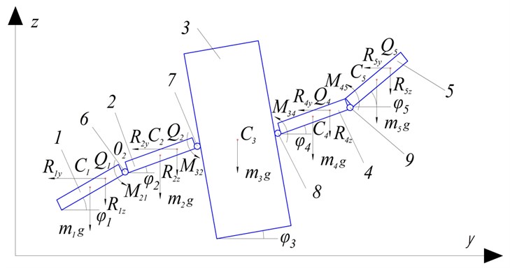
We consider the case when the object moves horizontally along axis ( const) or is in a hovering mode at a certain height above the surface ( const). This allows us to switch to a simplified mathematical model of the robot’s motion, by assuming that the projections of the position of the center of mass of the body along axes and , as well as its angle of rotation about point remain unaltered ( const, const, const). We also assume that links 1 and 5, 2 and 4 move in antiphase with equal amplitudes (, ) in order to achieve flapping motion of the wings. In this case the number of generalised coordinates is reduced to two and the vector can be written as follows:
During motion the studied system is subjected to the following forces: forces of gravity, , applied to the centers of mass of the links, torques , , and generated by actuators and that provide relative oscillatory movements of the links, forces of resistance , 1, 2, 4, 5, whose points of action, , are the centers of gravity of the diagram of the forces of resistance of the external environment, which are calculated as follows:
where – density of air; – velocity of point ; – effective area of link , – dimensionless coefficient of aerodynamic force.
The given forces can be broken down into two components – horizontal, and vertical, , as well as into the components, , directed along link , and , perpendicular to the link:
Since the force is proportional to the square of the velocity, , of the its point of application, while the velocities of the points, , of links 1, 2, 4 and 5 will be constantly changing during motion, we can assume that at different points of motion the diagrams of the forces of resistance on the links will have different forms and the position of the points will move along the links. We assume that the points, on the links, 1, 2, 4 and 5, are seperated by distances from the centers of mass, along, lengths . To calculate the distances, we assume that the points, are the centers of mass of the figures forces by the forces, . Since and , it is sufficient to determine the distances only for links 4 and 5:
where , and are coefficients determined by the formulas:
The distances, for 4 and 5, are calculated as follows:
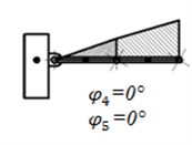
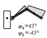
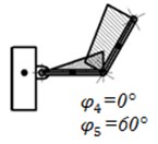
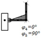
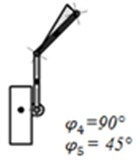
We assume that the linear and angular velocities of the robot body:, , and the angular velocities of the links: rad/s, while 0 rad. Then at different values of angles and we get the following form of the distribution of aerodynamic forces on the relevant links (Fig. 2).
Fig. 2Diagrams of distribution of forces of resistance along the lengths of the links 4 and 5
The system of differential equations describing the behaviour of the whole mechanical system in matrix form can be written down as follows:
where , are matrix coefficients, – matrix of generalized forces, which includes gravitational forces, forces of resistance and torques generated by the actuators, – diagonal matrix of the first derivatives of the coordinates .
For the particular case of horizontal flight or hovering, when the body is fixed, we will have two differential equations:
where is the central moment of inertia.
The control system that implements the given motion of the robot, in general form is shown in Fig. 3(a) (“Mechanical system”). Here the actuator torques play the role of reference signals and the angles of rotation of links 1, 2, 4 and 5 – the controlled variables. The coordinates of the center of mass of the body are generated at the output of the control system, but negative feedback channels are absent. In order to process the laws of oscillatory motion of links 4 and 5 when the boy is fixed the control system can be transformed into the form shown in Fig. 3(a) (“Links 4 and 5”). In it the number of generalized coordinates (, ) obtained at the output correspond to the number of control parameters, which are torques and .
Fig. 3a) Diagrams of control systems of the mechanical system and links 4 and 5 (horizontal flight and hovering modes), b) cylcogram of control torques of the automatic control system “Links 4 and 5”
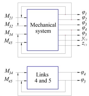
a)
b)
This work studies one of the possible control strategies, under which the torques acting on links 1, 2, 4 and 5 are equal in magnitude and opposite in direction (, ). To model the motion of the given system as an ornithopter it is necessary to alternate stages, in which the projections of the effective areas of the side links on axis , as well as the velocity of the points of application of the forces of resistance rise up to the maximum values and vice-versa when the same parameters decrease up to minimum values.
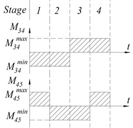
We will model the motion of the robot during horizontal flight along axis or in hover mode. Then, for the whole duration of the robot’s motion const, const, 0 work, , . The sequence of the stages of motion is shown in Fig. 4. The purpose of modelling is the generation of such control torques that will provide oscillations of links 4 and 5 with a change of the projections of their areas on axis and the velocities of points from the largest to the smallest and vice-versa.
Let the initial angles of links 4 and 5 be and , where – a certain fixed value of the angle. In the first stage torques and act at points and , as a result of which links 4 and 5 rotate up to the angles rad, . With the onset of the second stage torque changes its sign and at torque continues to act at point . As a result, the angles of the links attain the following values: and 0. In the third stage changes its sign and continues to act at point . At the end of this stage the angles attain the values 0 and . In the fourth stage torque continues to act at point , while reverses direction, as a result of which the angles are equal to the initial angles at the end of the stage.
Fig. 4Sequence of the stages of motion of the links of the mechanical system as an ornithopter
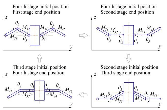
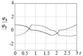
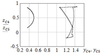
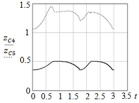
Fig. 5Graphs of: a) φ4t, φ5t and b) zC4yС4, zC5yC5
a)
b)
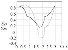
Fig. 6Graphs of: a) zC4t, zC5t and b) yC4t, yC5t
a)
b)
The parameters of the modeled object are as follows: 1 kg, 1 m, 4 rad. The results of modelling are shown in Fig. 5 and Fig. 6. From the graphs it can be seen that the control system correctly processes the given sequence of movements: links 4 and 5 execute oscillatory movements in the range: to . It can be seen from the trajectory graphs that point executes rotational motion, while point moves on a more complex trajectory, executing rotational-translational motion. The proposed method of motion of the mechanical system can be used for viewing terrain, collection of data on the composition of air, its temperature, humidity, etc. for the purposes of monitoring environmental parameters using ornithopters.
3. Conclusions
This paper considers a mechanical system consisting of five links connected to each other by active cylindrical hinges, whose side links execute oscillatory motion. The motion of the system takes place in an environment with resistance represented by aerodynamic forces, whose points of application are assumed to be moving along the lengths of the side links and taken as the centers of mass of the distribution diagrams of the stated forces. Such a system can be used to simulate a flying robot of the ornithopter type if alternation of stages, in which the horizontal projections of the effective areas of the given links and the velocities of the points of application of the forces of resistance increase and decrease during antiphase oscillatory movements of links 1 and 5, 2 and 4 with equal amplitudes, occurs.
The given system is considered in this paper as an ornithopter in horizontal flight or hovering mode at a certain height, which allows us to impose restrictions on the mobility of the robot body completely by fixing it in plane . We develop a mathematical model of motion was for links 4 and 5, as well a negative feedback control system for their angles of rotation, where the torques generated by actuators are used as control actions and the controlled variables are the angles of rotation of the links. A sequence of the stages of motion of the stated links is also presented and a cyclogram of control torques is given. The time functions of the corresponding generalized coordinates are obtained as a result of the numerical modelling.
References
-
Bolotnik Zeydis N. N. I. M., Zimmerman K., Yatsun S. F. Dynamics of controlled movements of vibrating systems. Theory and Control Systems, Izvestiya RAN, Vol. 5, 2006, p. 157-167.
-
Chernous’ko F. L. Optimal two-mass system of periodic motion in a resistant medium. PMM, Vol. 72, Issue 2, 2008, p. 202-215.
-
Volkova Yu L., Jatsun S. F. Simulation of the plane controlled motion of a three-mass vibration system. Journal of Computer and Systems Sciences International. Vol. 51, 2012, p. 859-878.
-
Jatsun S. F., Lupehina I. V., Panovko Ja G., Volkova Yu L. Dynamics of the vibration driven tool at its interaction with the processing material. 13th World Congress in Mechanism and Machine Science, 2011, p. 1-5.
-
Efimov S. V., Polyakov R. Y., Vorochaeva L. Y., Jatsun S. F. Bouncing dragonfly-like mini-robot. Fundamental Research, Vol. 9, 2015, p. 455-459.
-
Jatsun S.F., Lupehina I.V., Rukavitsin A.N. The study controlled motion of a jumping minirobot. Proceedings of the Higher Educational Institutions, North Caucasus Region, Vol. 2, 2011, p. 10-15.
About this article
Work supported by RSF, Project No. 14-39-00008.
