Abstract
In this paper we explore the resonant properties exhibited by insects during hovering and present a wing actuation mechanism based on the structure of the insect thorax. A mathematical model of the proposed actuation mechanism is developed. An analysis of the influence of spring stiffness, flapping frequency and drag coefficient on the torque and mechanical power required for wing movement is carried out. We show that driving the actuation mechanism at resonant frequency helps to reduce inertial costs of accelerating and decelerating the wings.
1. Introduction
The development of flapping wing aerial vehicles (FWAV) that imitate efficient natural fliers like birds and insects has been subject to active research in the field of robotics in recent years. The principles of flight used by these natural fliers can be used to design energy efficient FWAVs capable of avian maneuvers such as rapid takeoff, hovering, gliding and perching. One such principle is the exploitation of resonance observed in insects during steady state flight. Various studies have been carried out on the exploitation of resonance in FWAVs to reduce peak torques and power during the flapping cycle [1-3]. A comparison of FWAV projects based complexity, number of joints, actuator type, flapping frequency and control is given in [1]. Here a list of mechanisms that exploit resonance is also provided e.g. the Harvard fly. Khan et al. [2] develop a resonant flapping mechanism that incorporates torsion springs to generate complex insect-like wing motion. In this paper we present a simplified flapping mechanism inspired by the wing coupling in insects and carry out an analysis of the influence of spring and aerodynamic parameters on peak torques and power.
2. Object description
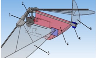
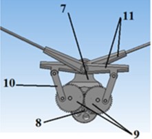
We define an insectopter as an aerial vehicle that imitates the flight of insects. Fig. 1 shows general views of 3D models and main components of the insectopter and the gearbox. The flapping mechanism of the robot includes gearbox 5, wings and servomotor 5, which rotates tail 6. The insectopter body 4 houses the gearbox, which transmits motion from the motor to the wings, accumulator and other electronic components of the robot’s control system. The wing coupling mechanism, which includes rotation limiter 1, is mounted on the leading edge spar of the wing. The limiters are used to control pitching motion of the wing and regulate the angle of attack. The gear unit shown in Fig. 1(b) consists of body 7, pinion 8, synchronizer 9, connecting rods 10 and rockers 11. The synchronizer comprises two gear wheels of equal diameter meshed with each other. It ensures synchronous flapping of the wings. When voltage is applied on the DC motor rotation is transmitted from the motor to the gear wheels of the synchronizer. The connecting rods are set into motion, which in turn pass flapping motion to the rocker on the wings.
The resonant properties observed in insects during flight help to reduce the inertial cost of accelerating and decelerating the wings. The insect thorax can be described as a damped oscillatory system since the wing is attached to the thorax via the protein resilin that possesses elastic properties [1]. Fig. 2(a) shows the wing coupling in the insect thorax [10] and a proposed simplified mechanical analog of the insect thorax.
Fig. 13D models of а) insectopter: 1 – rotation limiter; 2 – gearbox; 3 – wing surface; 4 – body; 5 – servomotor; 6 – tail; b) gear unit: 7 – body, 8 – pinion, 9 – synchroniser, 10 – connecting rod, 11 – rocker
a)
b)
Fig. 2а) Wing coupling in insect thorax, b) mounting of wing on an elastic suspension
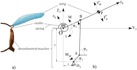
The following denotations are used in Fig. 2(b): – center of pressure; ; – drag; – motor torque; –actuator torque at the wing hinge – spring torque; – velocity of the center of pressure along axis . The coordinate system, is associated and rotates together with the wing. In Fig. 2(b) the gear mechanism represents the dorsolventral muscles in the insect thorax and the torsion spring– the protein resilin. The system can be considered as an oscillatory system whose motion about axis is described by the following second-order differential Eq. (1):
where – moment of inertia of the wing; – spring stiffness. Aerodynamic drag can be calculated using the following non-linear model:
where – drag coefficient; – surface area of the wing; – density of air. Based on the construction of the mechanism harmonic forced motion of the wing is assumed i.e. the angle of rotation of the wing, changes as follows:
where is the maximum flapping amplitude determined by the mechanism’s design; is the flapping frequency of the wing. Thus, we can find the actuating torque at the wing hinge, by substituting and into Eq. (1) and performing the necessary transformations:
In the expression above the first term, , reflects the torque required to overcome wing inertia, while the second, , reflects the torque required to overcome aerodynamic drag. Resonance can be observed in the system if the mechanism is driven at its natural frequency. The natural frequency of the system in the absence of drag is defined as follows:
From the above definition of natural frequency, we can see that the first term in Eq. (4) is nullified when i.e. when the mechanism is driven at its natural frequency. This leads to a reduction in the torque and mechanical power required for wing movement, especially in cases when wing inertia is considerably large. Resonant frequency in the presence of aerodynamic drag, , is the flapping frequency at which peak actuator torque is minimum i.e. the frequency at which the derivative of peak torque with respect to flapping frequency equals zero. Further, we study the influence of flapping frequency and spring stiffness on the peak actuator torque at the wing hinge for a wing using the following parameters: 0,5 m; 0,03 kg; 0,33 m; 0,0741 m2, 0,00333 kg/m2, 75°; 0,5; 1,3 kg/m3, where is the length of the wing.
3. Study of the dependence of peak actuator torque on flapping frequency at constant spring stiffness
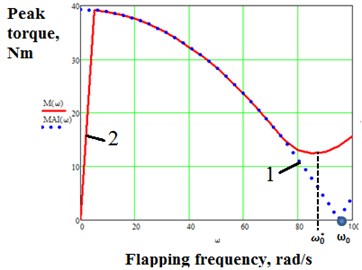
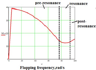
We will study the influence of flapping frequency on the values of peak torque at a fixed spring stiffness: 30 Nm/rad and 0100 rad/s. The natural frequency of the wing oscillations in this case is given by Eq. (5):94,9 rad/s. We first investigate the effect of flapping frequency on the amplitude of the torque required to overcome wing inertia, where , assuming zero aerodynamic drag i.e. (see Fig. 3). We also plot the graph of peak torque against flapping frequency in the presence of drag i.e. 0,5. We can see from the graph 1 in Fig. 3 that in the absence of resistance the torque required to overcome wing inertia decreases as flapping frequency increases and is nullified when resonance occurs. This in effect means that no torque is required to drive the mechanism at resonant frequency in the absence of aerodynamic drag. Notice that the resonant frequency is shifted to the left due to non-linear aerodynamic drag.
Fig. 3a) 1– Graph of AMi against flapping frequency for CD= 0; 2 – graph of peak torque against flapping frequency for CD= 0,5; ω0= 94,9 rad/s; ω0*≈ 85 rad/s, b) frequency regions
a)
b)
Three regions can be singled out on the graph: pre-resonance, resonance and post-resonance, as shown in Fig. 3(b). In the pre-resonance region the value of peak torque decreases as flapping frequency increases and attains a minimum value in the resonance region, which occurs due to the nullification of wing inertial forces as stated earlier. The value of peak torque begins to rise in the post resonance region as the flapping frequency increases. We can conclude that driving the mechanism at or close to the resonant frequency yields a significant reduction in the actuator torque, especially in cases when wing inertial forces are significantly large as compared to aerodynamic drag. A smaller actuator can therefore be used to drive the mechanism.
4. Study of the dependence of peak actuator torque on spring stiffness and drag coefficient
We study the dependence of peak actuator torque on the spring stiffness, where 030 Nm/rad. The value of drag coefficient is fixed at 0,5. Graphs of peak motor torque against flapping frequency are shown in Fig. 4.
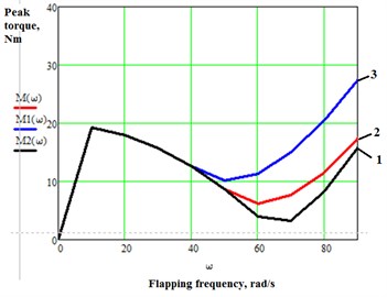
From the graphs we see that peak actuator torque in the absence of an elastic element increases as flapping frequency increases (see Fig. 4, graph 1). We can see that the graphs of peak torque for all mechanisms with an elastic element attain minimum values in the resonance region, which are significantly lower than the peak torque in graph 1. This study allows us to choose the optimum value of stiffness and control the natural frequency of the mechanism, . The graphs below show the results of the study of the influence of aerodynamic drag on peak actuator torque for a fixed stiffness, 15 Nm/rad.
From the Fig. 4, 5 we can see that aerodynamic drag begins to have a considerable effect on peak torque at flapping frequencies close to the resonant frequency, 67,1 rad/s in this case. Peak torque begins to rise proportionally to the drag coefficient value. As aerodynamic drag increases the value of resonant frequency is shifted to the left.
Fig. 4Graphs of peak motor torque against flapping frequency: 1) c=0; 2) c= 5 Nm/rad; 3) c= 10 Nm/rad; 4) c= 15 Nm/rad; CD= 0,5
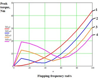
Fig. 5Graph of peak actuator torque against flapping frequency for different drag coefficient values:1) CD= 0,2; 2) CD= 0,5; 3) CD= 1,0; c=15 Nm/rad; ω0= 67,1 rad/s
5. Study of the effect of drag coefficient on the phase shift between flapping angle and actuator torque
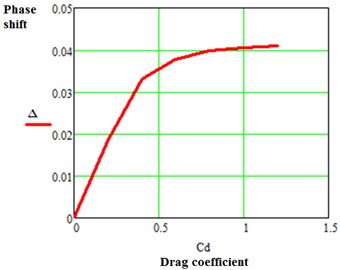
We study the influence of drag coefficient on the phase shift, , between flapping angle and actuator torque. In this study the phase shift was evaluated for different values of drag coefficient in the range: 01,2. Fig. 6 shows the obtained results.
From the graph we can see that phase shift at first increases linearly as the drag coefficient increases for 1. Phase shift arises in the presence of aerodynamic drag and as a result the graph of torque acquires a polyharmonical character. The average power in this case is non-zero due to the phase shift. As the phase shift rises, the average power required to drive the mechanism increases.
Fig. 6Graph of Δ against CD
6. Conclusions
In this paper the resonant properties of insects are studied. An actuation mechanism based on the thorax of insects is presented and a mathematical model describing the motion of the mechanism is given. An analysis of the influence of spring stiffness, flapping frequency and drag coefficient on the torque and mechanical power required for wing movement is carried out. It was shown that wing inertial forces are nullified at resonance and driving the actuation mechanism at resonant frequency helps to reduce the torque and mechanical power required for wing movement by cutting down the inertial costs of accelerating and decelerating the wings. It was also shown that resonant frequency can be tuned by varying the stiffness of the elastic suspension.
References
-
Bolsman C. T. Flapping Wing Actuation Using Resonant Compliant Mechanisms: An Insect-Inspired Design. TU Delft, Delft University of Technology, 2010.
-
Khan Zaeem A., Sunil K. Agrawal Design and optimization of a biologically inspired flapping mechanism for flapping wing micro air vehicles. International Conference on Robotics and Automation, IEEE, 2007.
-
Baek Stanley S., Kevin Y. Ma, Ronald S. Fearing Efficient resonant drive of flapping-wing robots. IEEE/RSJ International Conference on Intelligent Robots and Systems, 2009.
-
Maglasang Jonathan, et al. Aerodynamic study and mechanization concepts for flapping-wing micro aerial vehicles. Memoirs of the Faculty of Engineering, Kyushu University, Vol. 66, Issue 1, 2006, p. 71-82.
-
Deng Xinyan, et al. Flapping flight for biomimetic robotic insects. Part 1: system modeling. IEEE Transactions on Robotics, Vol. 22, Issue 4, 2006, p. 776-788.
-
Adnan Nahid Hasan, Mohammad Talha Talkin Alam Designing a Radio Frequency Controlled Biomimetic Flying Bird. Thesis, BRAC University, 2014.
-
Polyakov R. Y., Efimov S. V. Study of take-off motion of a flapping wing robot. Voronezh Institute, Vol. 3, 2014, p. 90-97, (in Russian).
-
Polyakov R. Y., Efimov S. V. Study of Controlled Synchronous Motion of a Flying Multi-Link Robot, Electro-Technical Complexes and Control Systems. Publishing House “Quart”, Voronezh, Vol. 3, 2014, p. 28-33, (in Russian).
-
Polyakov R. Y., Efimov S. V. Study of the Motion of a Flapping Wing Flying Robot during Take-Off, Electro-Technical Complexes and Control Systems. Publishing house “Quart”, Voronezh, Vol. 3, 2014, p. 41-45, (in Russian).
-
Resilin in Insect Wing Cross Section. Bugboy52.40, https://commons.wikimedia.org/wiki/ File:Resilin_in_insect_wing_crossection.svg.
About this article
Work supported by the Russian Science Foundation, Project No. 14-39-00008.
