Abstract
Traditional welded joint in steel frame design can be seen as completely rigid joint. And the high strength bolt end-plate joints have been used with popularity in multi-story frames because they have the advantages of requiring shorter assembly times, better seismic performance and good ductility. The performance of this kind of structure model under the condition of progressive collapse has not been analyzed. So, this paper aimed to solve this problem. ANSYS is applied in this article for the analysis of the performance of the capacity of unilateral extended end-plate connections through the method of numerical simulation and comparing with rigid joint. Then applying corner-general force curve of semi-rigid joint to the numerical analysis by using SAP2000. Establishing separate frames with rigid joints and semi-rigid joints, and analyzing the performance of each frame in the condition of progressive collapse. The analysis results show that the resistance of steel frame with semi-rigid joints is superior to rigid frame structure. It has better ductility, and is conducive to the further development of catenary stage.
1. Introduction
Progressive collapse refers to the small damage in structure that caused by any accident results in the upper unbalanced load which makes the damage inside the structure develops and eventually lead to wide collapse. Progressive collapse often causes serious social influence. It has carried out a large number of related research at home and abroad in recent years. And the purpose is to enhance the ability of structures to resist progressive collapsed after local failure occurred [1].
At present, related study mostly assumes that beam-column connections as fully rigid joints or ideal hinge, which is inconsistent with the actual structures [2]. Connected joints in practical structures are often between just rigid and articulated, which is known as semi-rigid joints.
2. The performance of semi-rigid joint
The stress distribution of high strength bolt end-plate joints is complex, for its contact condition between each element, the applying of bolt pretension and the plastic development of metal materials, as well as large deformation problems. Using ANSYS in elastic-plastic finite element analysis of high strength bolt end-plate joints, considering the material nonlinearity, geometric nonlinearity and nonlinear factors such as the contact status. This can get more correct stress and deformation performance of panels, as well as the formation and development of pry force, the distribution of high strength bolt tensile force [3].
3. Material and methods
Model of plate and bolt adopts 10 nodes hexahedron unit SOLID185 entity model. The contact unit and the target unit of CONT174 and TARGE170 have been set up between column flange and the end plate, nut and column flange, nut and end plate, and bolt bar and hole wall.
The steel plate ultimate tensile strength is 345 MPa () off 1.45 times of yield strength (). The yield strength of 10.9 bolt diameter of 20 high strength bolt is 940 MPa, and the tensile strength is 1050 MPa.
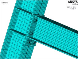
The column section is H400×350×12×16 and beam section is H400×300×12×16. The detail main size of model and end plate is shown in Figs. 1, 2. At the same time, establishing solid model of the same size frame with rigid joints. The final finite element model of semi-rigid frame as shown in Fig. 3.
Fig. 1The model of connection
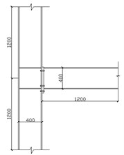
Fig. 2Structure of end-plate
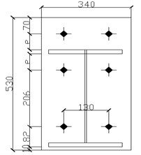
Fig. 3The model of finite element
4. Results
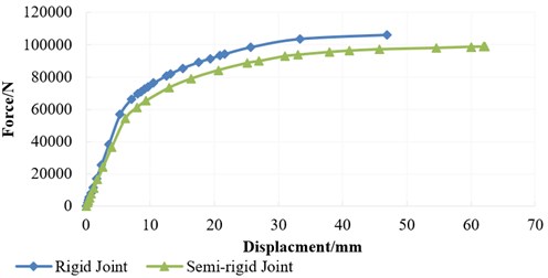
The load-displacement curve of semi-rigid frame and rigid frame is shown in Fig. 4.
From the diagram, the initial stiffness of rigid joint is 9.8 % bigger than semi-rigid joint. And the ultimate bearing capacity of the rigid joint is 7.1 % larger than semi-rigid joint, although its effect on the ultimate bearing capacity is smaller than the initial stiffness, but the bearing capacity of rigid frame is significantly greater than semi-rigid joint. But the brittle fracture in the subsequent stages of analysis such as the welding defects in rigid joint eventually lead to joint damage occurred. The destruction of semi-rigid joint is behind the rigid joint because of its better ductility. This is good for the development of catenary mechanism in frame structure.
Fig. 4Force-displacement curve of connection
5. The resistance of frame structures in progressive collapse. Material and methods
In order to determine the influence of semi-rigid frame in progressive collapse resistance, establishing two frames with semi-rigid joints and rigid joints. Nonlinear dynamic analysis and nonlinear static analysis have been applied and results have been compared.
According to the determine structure failure criterion in UFC2010 [4] of the United States, when structures destroyed or angle of the beam end more than 0.2 rad depending on the structure of progressive collapse happened. At the same time, the yield strength of steel will be multiplied by the amplification coefficient of 1.1 to consider the strain rate effect in the process of analysis according to the GSA [5].
Using finite element analysis software SAP2000 to establish a steel frame with 4×4 across and 5 layers, the height of each layer is 3.6 m, the column spacing of transverse and longitudinal direction is 9 m. The column section is 400 mm×350 mm×12 mm×16mm, beam cross section is 400 mm×300 mm×12 mm×16 mm, and all the steel are Q345.According to the FEMA356 [3], M3 plastic hinge has been applied in the ends of beams, and P-M2-M3 plastic hinge has been applied in he ends of columns. The weight of each component are included. According to the GSA [5], the load G = DL+0.25LL (DL as the dead load, LL live load). The frame model is shown in Fig. 5.
Fig. 5Finite element analysis models
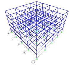
a) Stereogram
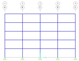
b) Profile
Alternate load path method is used in analyzing progressive collapse. To format the structure with local initial damage by dismantling one or several main stress components of root structure [6]. Then the remaining structure is analyzed with mechanics’ method, and to simulate rest structure during the process of progressive collapse by numerical method. This paper only analyzes the condition that outside column fails. The calendar function failure time take no more than 10 % of the remaining structure vertical base period. Using Reilly damping as structural damping,[7]. Its proportion coefficient can be decided according to the first two order frequency of the rest of the structure:
where [], [] represent mass and stiffness matrices respectively, , represent quality and stiffness coefficient, represent modal damping ratio as 0.02, and , represent the first two order frequency of the rest of the structure.
6. Results
6.1. Nonlinear static analysis results
The development of plastic hinge of rigid and semi-rigid frame under the Pushdown analysis are shown in Fig. 6.
By the figure of the development and distribution of plastic hinges, rigid frame structure and semi-rigid frame structures’ damage only over the failure columns’ studio and, no plastic hinge occurs on another cross beam. When the node displacement of rigid frame meets the failure criteria, the plastic hinge only in the phase of its plastic hinge curve of LS (that is, the stage of life safety). And at the time of semi-rigid frame meets the failure criteria, some of plastic hinges have developed into CP phase (that is, the collapse phase). There is a plastic hinge even come close to failure stage.
Analysis based on the above results can be concluded that the semi-rigid frame structure under collapse load, the failure pattern is relatively more ideal than rigid framework with more plastic hinges in the failure across, at the same time with more fully developed plastic hinges. It means that the ductility of the frame is higher, and dissipates more energy. It can help the overall structure to consume more energy to a certain extent by redistributing plastic internal force in the process of progressive collapse.
Fig. 6Plastic hinge result of frames
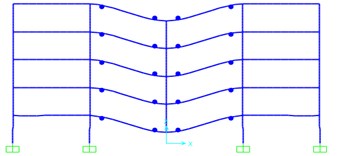
a) Rigid frame
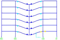
b) Semi-rigid frame
6.2. Dynamic analysis results
The dynamic response of structures in progressive collapse can be achieved by vertical displacement of failure joints and the inertial force of upper structures [1].
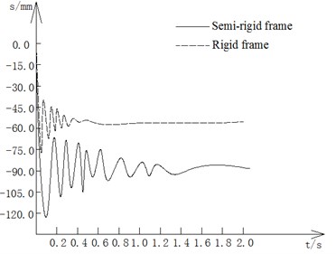
The vertical displacement time history curve of failure joint of rigid and semi-rigid frames are shown in Fig. 7.
Fig. 7The displacement-time curve of failure point
7. Discussion
As shown in the figure, the maximum vertical displacement of rigid frame is 75.48 mm, occurs in 0.07 s. And the maximum vertical displacement of semi-rigid frame is 121.52 mm, in 0.12 s. In addition, the displacement time history curve of semi-rigid frame failure joint is in fluctuation condition before 1.3 s. After stabilizing, and control in 89.42 mm or so. Just pick up rigid frame achieved stable after 0.5 s, and finally controlled at about 57.67 mm. According to the analysis results that the vertical displacement of latter frame is much smaller than the former’s. At the same time, the structure under damage conditions achieves maximum response much faster, and easily tends to be stable, which means rigid frame’s stiffness is much larger than semi-rigid frame. It also has better capability of resistance of progressive collapse. However, the semi-rigid frame has better ductility.
Axial force of right side beam above the failure joint are shown in Fig. 8.
Fig. 8The force-time curve of left beam
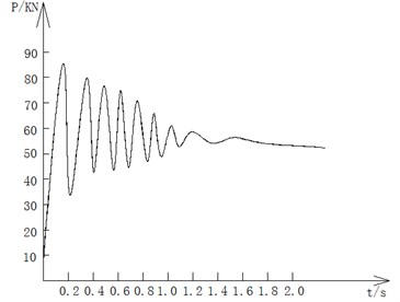
a) Semi-rigid frame
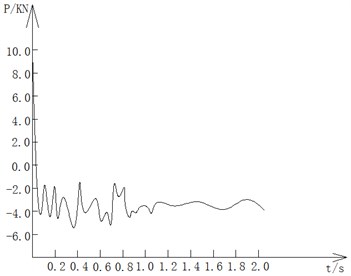
b) Rigid frame
The axial force of right side beam above the failure joint in semi-rigid frame has obvious vibration, and greatly increased, and finally gets in the tensile state. Thus the beam-column substructure has entered the stage of catenary that both sides of the beam resist progressive collapse by Rachel action. At this time, if continue to increase the upper load, the structural damage is likely to occur. The axial force of right side beam above the failure joint in rigid frame is pressure which explain the structural resist to fall through the beam mechanism. There is a certain distance from structure progressive collapse. From the above analysis, semi-rigid frame has better ductility, catenary effect will develop more fully under the condition of progressive collapse. It will consume more energy while its vulnerability is larger than rigid frame.
8. Conclusions
Based on finite element analysis between rigid and semi-rigid frames, the following conclusions have been obtained:
1) The failure joint displacement of semi-rigid frame is the largest as well as its oscillation amplitude, which shows that it has better capability in energy dissipation. But due to the lesser stiffness, failure joint displacement is too large because of the lack of effective support. Through the analysis of the internal force of beam, it can be found that this kind of frame structures are more likely to enter the stage of catenary under collapse conditions, and help dissipating energy.
2) The rigid frame has better stiffness. Rigid beam with rigid joint can generate effective support for the structure above the failure joint, so that structure is more likely to enter a stable state. But its deformation ability is poorer, energy consumption ability is lower than semi-rigid frame. The brittle failure often happens under the condition of progressive collapse.
3) The vulnerability of semi-rigid frame is lager. So it should be carefully used in the inverted design of structure. Rigid and semi-rigid joints should be mutual fusion used in progressive collapse resistance protection.
References
-
Minimum Design for Buildings and Other Structures. ASCE/SEI7-05, American Society of Civil Engineers, USA, 2006, p. 207-208.
-
Hendrick A., Murray T. M. Column Web Compression Strength at End-Plate Connections. Research Report No. FSEL/AISC83-01, Fears Structural Engineering Laboratory, School of Civil Engineering and Environmental Science, University of Oklahoma, Norman, 1983.
-
Prestandard and Commentary for the Seismic Rehabilitation of Buildings. FEMA 356.
-
Design of Buildings to Resist Progressive Collapse. UFC4-023-10.
-
Progressive Collapse Analysis and Design Guidelines for New Federal Office Buildings and Major Modernization Projects (GSA2003).
-
Gu Xiang Lin Design methods for buildings to resist progressive collapse. Structural Engineers, Vol. 25, Issue 5, 2009, p. 142-148.
-
Qian Jiaru, Hu Xiaobin Dynamic effect analysis of progressive collapse of multi-story steel frames. Journal of Earthquake Engineering and Engineering Vibration, Vol. 28, Issue 2, 2008, p. 8-14.
-
Wheeler A. T., Clarke M. J. FE Modeling of four-bolt tubular moment end-plate connections. Journal of Structural Engineering, Vol. 126, 7, p. 816-822.
-
Li Guo Qiang, Shi Wen Long Design of Steel Frames with Semi-Rigid Connections. China Architecture and Building Press, Beijing, 2009.
-
Izzuddin B. A., Vlassis A. G., Nethercot D. A. Progressive collapse of multi-storey buildings due to sudden column loss. Part 1: simplified assessment framework. Engineering Structures, Vol. 30, Issue 5, 2008, p. 1308-1318.
About this article
