Abstract
This paper introduces a novel design method of virtual prototype based on OpenGL. This method can be applied to describe the principle of work and show the operating condition of the robot, plays a significant role in promoting structural design and system optimization of the robot. And in this way with CAD modeling and VC++ programming techniques developed a kind of virtual prototype system of PJR-2X shotcrete robot, solved the issue of the establishment of the complex model based on OpenGL
1. Introduction
Virtual Prototype Technology, a new kind of technology developed gradually in the 1980s, integrates CAD modeling technology, computer collaborative technology, user interface design, design process management and virtual reality technology. And finally a computer model is formed, which can reflect the actual product’s features, including the appearance, structure and the characteristics of kinematics and dynamics. With the help of this technology, we can build structural model of mechanical system on the computer. Accompanied by the three-dimensional visual interactive display methods, the kinetic characteristics of the system can be simulated in a real environment, which break away from the bound of two-dimensional drawings.
The PJR-2X model shotcrete robot, made by our college’s robot research center, is the first coal mine robot in our county. With the properties of high reliability, simple structure and convenient operation, it can be used as the appropriative concrete spraying equipment for the port of coal mine or underground engineering tunnel. Based on this type of robot, this paper shows a brief introduction to its basic design structure and expounds a novel virtual prototype design method which is based on OpenGL and combines several other software at the same time.
2. The operating principle of the shotcrete robot
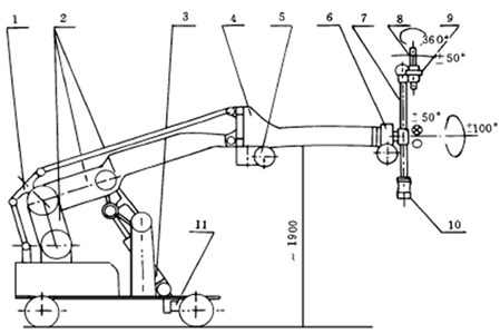
According to the requirements of shotcrete work’s characteristics, the shotcrete robot, shown in Fig. 1, is designed to be a kind of closed four-bar mechanism. Its working principles are: hydro-cylinder 3 drives four-bar linkage 2 of big arm to lift up and down, which makes the front of the big arm move along a plumb line, therefore , and it is ensured that the parallel four-bar components of the forearm can move up and down along the vertical direction;hydraulic motor 5 drives forearm parallel four-bar linkage to swing along the horizontal direction, which can be used to adjust the relative distance between the spray gun and tunnel wall , and it is also guaranteed that the angle of the spray gun and tunnel wall is invariant; hydraulic motor 6 drives spray gun rod 7 to rotate in the scope of minus 100 degrees to 100 degrees; an angle of 3 degrees is formed by Spray gun head 8 relative to the center of axis, Hydraulic motor 9 can drive this angle to rotate continuously, and it makes certain that spray gun head circular moves along a circular, which can Conform to the requirements of the shotcrete technology; Hydraulic motor 10 derives spray gun head 8 to swing in the scope of minus 50 degrees to 50 degrees for the purpose of the adjustment of posture; hydraulic motor 11 derives vehicle plate walk back and force on the track. The above mentioned principles can be ruminated through Fig. 1.
Fig. 1Shotcrete robot mechanical structure: 1 – balance rod; 2 – big arm four-bar linkage; 3 – big arm pitching oil cylinder; 4 – forearm four-bar linkage; 5 – hydraulic motor (forearm swing); 6 – hydraulic motor (spray gun rod rotation); 7 – spray gun rod; 8 – spray gun head; 9 – hydraulic motor (spray gun head rotation); 10 – hydraulic motor (spray gun head swing); 11 – hydraulic motor (drive vehicle plate)
3. The design ideas of virtual prototype
Within most software which can design virtual prototypes, the combination of Visual V++ and OpenGL has its unique superiority in the respect of building a robot prototype system. Firstly, V++ has a strong interactive processing ability and it is operated simply. Secondly, OpenGL is an open 3-D graphic software package, which can be run under different operating systems. OpenGL has a good portability and the powerful ability of graphic processing as well, which is suitable for building the robot’s mechanical structure and conducting movement simulation. Finally, the interface, between VC++ and OpenGL, is convenient and accurate. As long as the corresponding library files and the necessary program interface are contained, we can design by using the interface between OpenGL and Windows.
Fig. 2Robot parts processing flowchart (swing arm section)
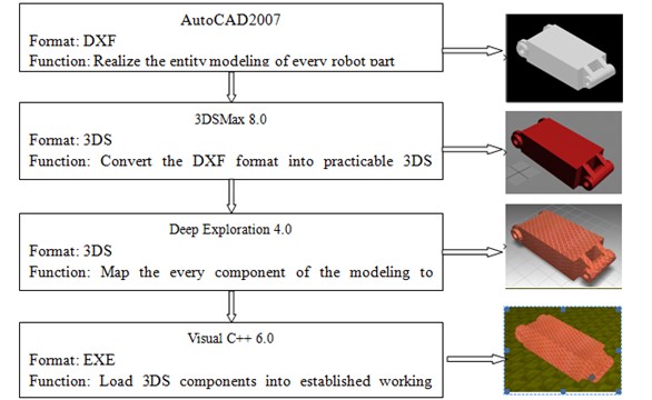
The shortcoming is that OpenGL can only provide the modeling function which contains basic geometric elements, and the advanced command of 3-D model cannot be offered, which makes certain difficulty when OpenGL sets up complex model. AutoCAD can conveniently provide accurate modeling of complex geometric entities, whereas, in the way of object rendering and procedures, it is unsatisfactory. For these reasons, in the design of the virtual prototype of the robot, using AutoCAD to modeling the robot and providing these model components for 3DSMax, Deep Exploration and OpenGL for secondary processing can realize a strong realistic motion structure of robot.
If a shotcrete robot is split into 20 parts, and every part is solidly modeled by using AutoCAD, we can obtain DXF files. On the one hand, this type of file has small program kernel, high reliability and good scalability. But on the other hand, it has relatively complex structure, tedious programming, slow execution speed and poor portability. In view of these, it is need to use 3DSMax 8.0 to convert them into 3DS files. And then Deep Exploration 4.0 is put into the files for rendering and texture, so finally visual C++ 6.0 is lead into a working scene that is build based on OpenGL, which can improve the shortcomings by the above steps. The resources about building OpenGL work platform and how to import the 3DS file are relatively abundant, there is no need to be repeat here.
4. The realization of motion structure
The part, which is more difficult to achieve in the mechanical structure of shotcrete robot, is large arm four connecting rod part. The whole structure makes lifting movement in the vertical plane. The original posture of virtual prototype at runtime is shown in Fig. 3. This part is composed of the base of the car body, swinging arm, big arm, rod 1, rod 2, balanced rod, pendulum body, bracket and oil cylinder.
Fig. 3Shotcrete robot four-bar linkage structure
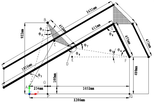
4.1. The calculation of initial parameters
From Fig. 3, when the total length between the hydraulic oil cylinder and piston rod is :
The initial value of is 670 millimeters. And the original angles of and are respectively 12.507 degrees and 35.885 degrees. The degree of angle is fixed, which is 12 degrees.
Assuming that the coordinate of the intersection point of pendulum body and big arm is (, ). There:
and then:
On the one hand, the angle of swing arm and the horizontal line, an angle sum of and , which is a intersection angle between the rod 1 and horizontal line as well, is solved. On the other hand, the intersection angle between swing arm and big arm, which is the angle of the rod 1and rod 2, is solved as well. From these, the linkage of big arm of four-bar can be come true.
4.2. The implementation of program
What is derived out by the above formula is the initial posture of each joint of the robot. In practice, the total length of hydraulic cylinder and the piston rod is (670) millimeters. is the stroke that is generated for the reason of the position rod out from oil cylinder. Modifying this variable can control the pitching of the big arm:
float ;
Solve the degrees of each angle:
float ;
Solve the degrees of each angle:
float ;
float ;
float ;
float ;
; // Solve
; // Solve
; // Solve
// The coordinate of the intersection point of pendulum body and big arm is (, )
;
;
; // Solve
; // Solve
; // Solve
; // Solve
The following is the kinematic implementation for the structure of big arm four-bar linkage (assuming that the point is the original of coordinates). Then import the swing arm, the big arm, balance rod into 3DS components in turn. (The ways of importing for rod 1and rod 2 are same).
// The swing arm
glRotatef(,1.0,0.0,0.0);
// The assembly parts move anticlockwise () degrees around -axis
m_drawGL→Scene(18,0,0,0,0,0,0.005);
// Import the swing arm
// The big arm
glTranslatef(0.0,0.0,0.27);
// Move 54 millimeters along -axis to make the shaft center of the head of big arm coincide with the shaft enter of the end of the swing arm.
glRotatef(,1.0,0.0,0.0);
// The assembly parts move anticlockwise () degrees around -axis to realize linkage of big arm and swing arm.
glTranslatef(0.0,0.0,–3.075);
// The coordinate system moves 615 millimeters along negative direction of -axis, and the origin of coordinate system arrives the point .
m_drawGL→Scene(21,0,0,0,0,0,0.005);
// Import the big arm
// The balance rod
glTranslatef(0.0,0.0,3.075);
// The coordinate system moves 615 millimeters along positive direction of -axis, and the origin of coordinate system arrives the point .
glRotatef(90,1.0,0.0,0.0);
// The assembly parts move clockwise () degrees around -axis to make the balance rod be in a vertical state.
m_drawGL→Scene(22,0,0,0,0,0,0.005); // Import balance rod
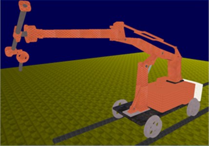
In accordance with the above method, after importing all the joint parts in sequence into the working scene build by OpenGL, a virtual prototype of shotcrete robot, showed in Fig. 4 and Fig. 5, can be received. Compared with robot prototype, this shotcrete robot has the same size and movement posture. It is entirely feasible that the operation of shotcrete robot’s work is simulated through the control of keyboard’s keys.
Fig. 4Virtual prototype system of shotcret robot (initial posture)
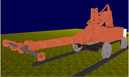
Fig. 5Virtual prototype system of shotcret robot (work posture)
5. Conclusions
The virtual prototype design method elaborated on this paper is based on OpenGL, and this method combine with CAD modeling and VC++ programming technology for development, which has very important significance to verify the robot’s working principle, operating scene, and the effectiveness of the kinematics equations. The virtual prototype system that is designed by this method, such as PJR-2X shotcrete robot, can be used to simulate the movement characteristics of the robot and establish optimal operation scheme and algorithm to solve the problems of robot design, manufacture and operation. The prototype system can be used for teaching demonstration, which can achieve good teaching effect.
References
-
Beisi Z. C., Ying S., Tongkui G. Automatic guided vehicle (AGV) Summary of development. Chinese Manufacturing Information, Vol. 1, 2010, p. 53-59, (in Chinese).
-
Bing Hui F. Shotcrete robot hydraulic system design. Journal of Coal Science and Technology, Vol. 3, 1998, p. 11-14.
-
Dong C. Three-Dimensional Motion Simulation and Finite Element Analysis of M_6iB FANUC Robotics. Xi’an University of Technology, 2007, p. 19-20.
-
Fuguang B. Research on agricultural products traceability mechanism based on RFID. Advance Journal of Food Science and Technology, Vol. 6, Issue 8, 2014, p. 1008-1015.
-
Hua Y., Xin Cheng T., Chuan Jun X. The implementation and design of industrial robot 3D simulation system. Robot Technique and Application, Vol. 5, 2002, p. 36-38.
-
Shreiner D., Mason W., Jackie N., et al. The OpenGL Programming Guide (Sixth Edition). Mechanical Industry Press, Beijing, 2009, p. 63-285.
-
Xiu Feng W. SQP algorithms in balancing rotating machinery. Mechanical Systems and Signal Processing, Vol. 21, 2007, p. 1469-1478.
-
Yongding W., Jiapeng Y. RFID and AGV systems integration and application in the distribution center. Computer Systems Applications, Vol. 11, 2011, p. 131-134, (in Chinese).
-
Wang Z., Chang Y. Z., Zhang J. G. The description of the robot motion in a virtual environment. Journal of Applied Science and Technology, Vol. 5, Issue 5, 2001, p. 9-10.
About this article

