Abstract
To overcome the difficulty in identifying the fatigue crack in key parts of aerospace structure, a kind of methods aimed to monitor the crack length based on matching pursuit (MP) method and binary tree support vector machines (BT-SVM) classification algorithm was developed. In this method, Lamb wave signals were decomposed into a linear combination of several Chirplet atoms by MP method, and then the matching parameters were extracted as feature vectors for training and testing in BT-SVM classification algorithm. At the same time, a lug joint model was created with a certain ratio and the effect of crack extension on Lamb wave signals propagation was studied. At last, fatigue loading experiments were carried out in lug joints and tail reinforced frames of aircraft. The results showed that this method can monitor the length of fatigue crack effectively, which presents a new approach for monitoring the fatigue crack.
1. Introduction
Aerospace structures often suffer from a variety of loads which may lead to crack, especially at the stress concentration portion. Once the crack which is small or located inside the structures is not detected in time, aircraft catastrophic accidents will occur. Nowadays, there are four popular damage detection methods applied into use which include acoustic emission detection [1], thermal imaging detection [2], eddy current detection [3], ultrasonic scanning detection [4]. But the structures must discontinue using when applying these methods. Also, overweight detection system and expensive cost make it unrealistic to monitor the aircraft in real time. Therefore, it has important significance to develop a method aimed to monitor the crack length of aerospace structure online.
Data mining method [5] opens a new way to recognize damage. It uses classified sensor signal samples as guide to identify the type of similar damage. Classification method based on neural network classifier is popular in structural health monitoring because of its strong ability of self-organize and self-study and better property of nonlinear systems classification. But neural network is easily affected by complex network structure, local extremum, over-fitting, and insufficient generalization capability and so on [6]. Support vector machine was proposed by Vapnik in 1995 [7, 8]. It has some advantages when solving the problems of small sample, nonlinear and high-dimensional pattern recognition. Also, it makes up for the disadvantages of method based on neural network.
Many scholars have research on the application of SVM in structural damage identification. Roh and Park et al. used SVM to detect the loose of bolt in jointed steel plates which based on lamb waves [9]. Isa et al. used SVM to detect the damage in oil pipeline which based on lamb waves [10]. Liu Long and Meng Guang applied SVM into the damage diagnosis of beam-like structures, and obtained damage localization and damage degree through using modal frequency as feature parameter [11]. Yuan S. F. et al. diagnosed the fault of turbo-pump rotor based on SVM [6]. These researches showed that damage identification methods combined with SVM can identify damage localization and damage degree. But in the aerospace structure, quantitative identification of crack length is still a challenging task due to the nonlinear relationship between crack length and the attenuation of lamb waves.
Traditional multi-class classification methods based on SVM include “One-Versus-One” (OVO) [12], “One-Versus-Rest” (OVR) [13] and so on, but all of them may appear the situations of low computational efficiency and inseparable overlapping region. A SVM classification method based on binary tree structure which called Binary Tree Support Vector Machine (BT-SVM) can solve these problems [14].
In recent years, some time-frequency analysis methods were used to analyze the monitoring signals such as short-time Fourier transform, wavelet transform, Hilbert-Huamg transform and so on, but the time-frequency resolution obtained by these methods is not optimal and they do not take the dispersion characteristic into account. Some researchers use matching pursuit method to monitor the signals. Hong et al. used matching pursuit method to analyze the wave signals, but they assume that the wave signal is single-mode and not dispersive [15]. Ajay et al. also utilized matching pursuit method based on Chirplet dictionary to process Lamb wave signals in a plate, but they do not establish the relationship between the dispersion and the chirp rate of the Chirplet atom [16]. Zhong Chen et al. extracted the impulse energy ratio by projecting on the selected atoms based on the matching pursuit method [17].
In this paper, a kind of method to monitor crack length based on matching pursuit (MP) method and classification algorithm which based on binary tree support vector machines (BT-SVM) was developed. In this method, firstly, the feature vectors were token by using matching pursuit method which based on Chirplet atoms dictionary base that can reflect the information of lamb waves accurately and sensitively. Secondly, the effect of crack extension on lamb wave signals propagation was studied that laid a certain foundation for experiment research. At last, fatigue crack expansion experiments were carried out in lug joints and reinforced frames of aircraft. The results showed that the proposed method is feasible and effective.
2. Classification methods based on binary tree support vector machine
SVM method aimed at two-class classification originally. How to expand to multi-class classification effectively is also one of the important content of research.
Multi-class classification based on binary tree support vector machine take all classes divided into two subclasses, and then take these two subclasses divide into two second subclasses respectively. By analogy, until all points just have one class. A complex multi-class classification problem can be transformed into some two-class classification problems. Each point use two-class SVM classifier which based on OVR method as classification function.
In the algorithm implementation process, the class which was first identified will be removed, thus comparison times can be reduced as far as possible at each point. As seen in Fig. 1, four-class classification problem can be solved.
Fig. 1Construction of multiple hyperplanes for BT-SVM method
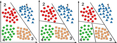
The advantage of this method is that k-1 optimal classification hyperplanes just needed to be set up for -class classification problem. Also, this method can improve computational efficiency, because data of a certain class were removed after every classification. In addition, it can give priority to some kinds of damage and terminate algorithm automatically when these damage have been detected. For example, bolted joints structure may consider torsional failure (damage A) firstly rather than structural damage (damage B) and it can terminate algorithm when failure of the bolts has been detected [5, 18]. The identification of crack length is just according to the sequence of the crack propagation because damage just exist one kind in this paper. In the process of testing, in order to avoid some points are divided into more than one class, the points which are divided into class-A at the first time will be removed from the testing set and then class-B will continue to classify.
3. Matching pursuit feature extraction method based on Chirplet atoms
Matching Pursuit (MP) method is a kind of adaptive signal processing method which was proposed by Mallat and Zhang in 1993 [19]. At the same time, Qian and Chen also put forward similar method [20]. This method projects iterative signals on enormous waveform dictionary base and choose the most appropriate waveform that can match a certain period of signals to be analyzed. MP method overcomes some weaknesses that the window function of short-time Fourier transform is fixed and frequency parameter is inversely proportional to scale parameter of window function in wavelet transform. It can use waveform which matches time-frequency characteristics of signal to represent signal. MP method is widely applied in many fields, such as image processing, signal processing of biomedical science, signal processing of earthquake, structural health monitoring and so on.
Assuming signal belongs to Hilbert space . MP method transforms signal into the linear combination of time-frequency atoms by multiple iterative decomposition. Let be , take decomposition at m-time as an example to illustrate:
a) Choose best atom from dictionary base :
b) After step (a), residual value of signal becomes the following value:
The process of iteration is controlled by the number of iterations or residual value of signal. After iterative decomposition for times, the signal was decomposed as follows:
where and are orthogonal in the process of decomposition and whole process satisfies the law of conservation of energy. When , the energy of residual signal is close to zero, its form is as follows:
In this paper, MP method chooses dictionary base consisted of Chirplet atoms. It can be written as:
where is index and is scale, is time-center, is angular frequency, is chirp rate. The angular frequency of this atom .
MP method based on Chirplet atoms can decompose Lamb wave signals into a linear combination of some atoms. Every Chirplet atom can be uniquely determined by (the time of arrival), (chirp rate) and (amplitude), so these parameters can reflect the information of original signal accurately. When the number of atoms is, the feature vectors can be constructed as:
4. Simulation research on the influence of crack length on signals
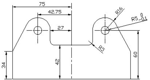
In order to study the influence of crack propagation on PZT sensor signals, the finite element model of aluminum lug joint had been set up based on ABAQUS. Its dimension parameters were shown in Fig. 2, elasticity modulus 72.9 GPa, Poisson ratio 0.3, density 2730 kg/m3, thickness 6 mm and these holes are reaming.
Fig. 2Schematic diagram of lug joint
As shown in Fig. 3, two square PZT sensors had been created around the stress concentration areas, S1 was used to excite signal, S2 was used to receive signal. Excitation signal adopted narrow band signal modulated by Gauss window:
where is step function, is the amplitude of excitation signal, is the number of wave crests, is the center frequency of excitation signal. In this paper, , .
Fig. 3The position of sensors and prefabricate crack
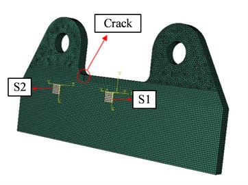
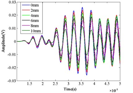
The crack was simulated by removing some elements in the stress concentration area. Six situations were studied whose crack length is 0 mm, 2 mm, 4 mm, 6 mm, 8 mm, 10 mm respectively. Fig. 4 shows the simulation signal of different crack lengths. The attenuation of received Lamb wave signals is becoming more and more serious with the increasing of crack length. This phenomenon laid the foundation for the following experiment research.
Fig. 4The simulation signals of different crack length
5. The experiment research on lug joint
5.1. Experiment set-up and experiment process
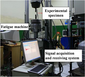
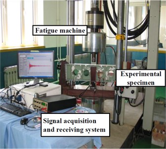
The experimental specimen is aluminum lug joint. As shown in Fig. 5(a), sinusoidal periodic loading was applied by American MTS fatigue machine. Its amplitude is 10 kN and loading frequency is 2 Hz. Narrow band signal was generated by NI-PX15412 signal generator as excitation signal and its center frequency is 300 kHz. The signal was received by NI-PXI6115 data acquisition card.
Fig. 5a) Experimental set-up of lug joint and b) sensors arrangement
a)
b)
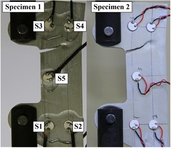
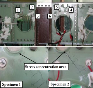
As shown in Fig. 5(b), PZT sensor network was arranged in the stress concentration area. The diameter of sensor is 6 mm, sickness is 1mm. Every sensor can excite signal and receive signal.
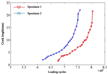
Fatigue loading experiments have been done for two experimental specimens in the process of experiment. The upper stress concentration area was first pulled open for both of them. Experimental data were collected when fatigue machine stopped working. Data of 31 kinds of states were collected in total. Fig. 6 records the crack extension process of lug joint with the increasing of loading cycles.
Fig. 6The crack extension process of lug joint
5.2. Signal processing based on matching pursuit method
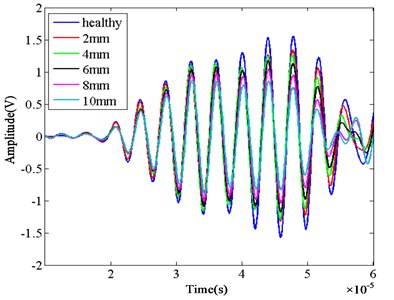
Six states were chosen to analyze from the data of two specimens, every sample of every state intercepts 400 points for analysis. Different damage states can be defined as: (1) C1 → healthy, (2) C2 → 2 mm, (3) C3 → 4 mm, (4) C4 → 6 mm, (5) C5 → 8 mm, (6) C6 → 10 mm. Fig. 7 shows Lamb wave signals corresponding to every state of specimen 1. It can be seen that the amplitude of received Lamb wave signals have certain attenuation. This is consistent with the simulation results.
Fig. 7The Lamb wave signals of different crack length
C1 signal of specimen 1 was decomposed by using MP method. When the number of atoms is five, Fig. 8 shows the reconstructing signal and residual signal. Fig. 9 shows the time-frequency energy distribution obtained by using matching pursuit method, where scale , angular frequency .
The number of atoms is ten in this experiment. When the feature vectors were extracted according to Eq. (6), time-center and chirp rate should amend the magnitude. Table 1 shows samples of parts with first two atoms.
In order to explain the superiority of MP method, the same signals had been analyzed through two different methods. 30 groups of samples were taken from every class of Specimen 1and it is a total of 180 groups. The dimension of every sample is 400. First of all, normalization processing was made for these data. Then principal component analysis (PCA) was made for them and the first three principal components were chosen for plotting. Fig. 10 shows that sample points exist sizable overlapping area and it has certain difficulty to separate these points. If feature vectors were extracted by MP method firstly and then PCA was made for them. Fig. 11 shows the result of this situation. Obviously, sample points of same class become more concentrated. Sample points of different class still exist some overlapping area, but it’s relatively easy to separate them. When the number of atoms is ten, the dimension of signal reduced to 30 after extracting feature vector. So, this method can greatly improve processing speed when facing large data scale.
Fig. 8Reconstructing signal and residual signal with 5 atoms
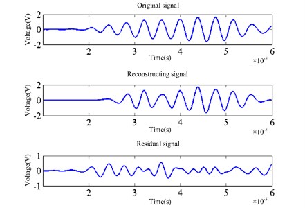
Fig. 9The time-frequency energy distribution obtained using matching pursuit method
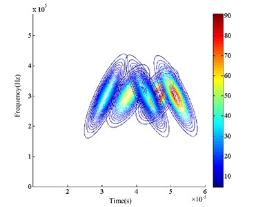
Fig. 10PCA of original signals
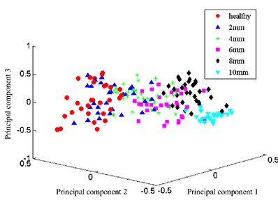
Fig. 11PCA of MP feature vectors extracted from signals
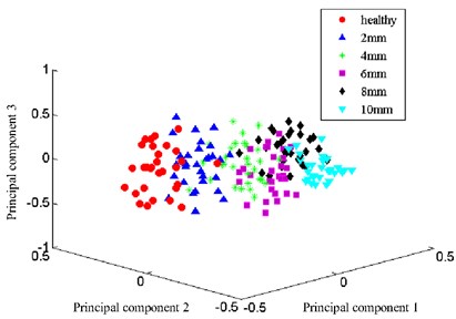
Table 1Samples of parts with 2 atoms
4.5998 | 5.1245 | 0.5232 | –1.0924 | 1.0729 | 0.9989 | |
4.5998 | 5.1247 | 0.5200 | –1.0902 | 1.0735 | 0.9984 | |
4.6997 | 3.3027 | 0.4495 | –0.6338 | 0.8707 | 0.7350 | |
4.6996 | 3.3027 | 0.4492 | –0.6339 | 0.8706 | 0.7345 | |
4.7071 | 3.3274 | 0.7458 | –06585 | 0.9342 | 0.7556 | |
4.7071 | 3.3274 | 0.7469 | –0.6598 | 0.9350 | 0.7556 | |
4.6699 | 3.4289 | 0.5363 | –0.5339 | 0.9024 | 0.7804 | |
4.6699 | 3.4290 | 0.5350 | –0.5287 | 0.9023 | 0.7804 | |
4.5733 | 3.4308 | 0.7498 | –0.4718 | 0.7457 | 0.6430 | |
4.5733 | 3.4308 | 0.7489 | –0.4718 | 0.7458 | 0.6427 | |
3.5333 | 4.5375 | 0.5983 | 0.5000 | 0.5356 | 0.5147 | |
3.5333 | 4.5375 | 0.5966 | 0.5000 | 0.5355 | 0.5152 |
5.3. Experimental results and analysis
This experiment mainly studied the crack extension process of upper stress concentration area. The data of specimen 1 were used to set up training model and the data of specimen 2 were used for testing.
100 groups of samples were extracted from every state of specimen 1 and specimen 2 separately. Feature vectors were extracted by using MP method and then imported into BT-SVM classification algorithm for training and testing. There was a partial overlap between the data, so a certain error was allowed to avoid the situation of excessive matching and lack of universal property. The training error is 10 %. Through interactive proof, better classification effect can be obtained when kernel function parameter and penalty factor .
As mentioned in Section 2, the identification of crack length just according to the sequence of the crack propagation when there is only one kind of damage. The sequence of damage identification is C1-C6. The consequence of testing is showed in Table 2, it shows that data points of class C1 have a very good classification effect which correspond with the classification method proposed in this paper. Some data of other class were classified into class C1 and these data should be removed from class C1 when continue to classify. This will partly reduce accuracy of latter forecast, but it reduces data size and improves classification effect.
Table 2The test result of lug joint
Identified class | |||||||
C1 | C2 | C3 | C4 | C5 | C6 | ||
Real class | C1 | 88 | 7 | 4 | 1 | 0 | 0 |
C2 | 11 | 82 | 3 | 2 | 1 | 1 | |
C3 | 7 | 8 | 80 | 2 | 2 | 1 | |
C4 | 6 | 3 | 6 | 80 | 3 | 2 | |
C5 | 4 | 3 | 4 | 8 | 79 | 2 | |
C6 | 2 | 3 | 5 | 5 | 10 | 75 | |
As shown in Fig. 12, normalization processing of the distance between sample points and optimal classification hyperplane were made for showing the degree of overlap between the data vividly at the first classification. It is obviously that just a small number of data of class C1 were classified into other class while relatively more data of C2-C6 were classified into class C1.
As can be seen from Table 3, BT-SVM method improves computational efficiency compared to OVO-SVM and OVR-SVM multi-class classification method in the condition that there is not big difference in test accuracy.
Fig. 12Distance from the optimal hyperplane
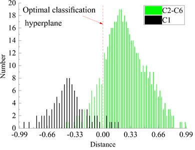
Table 3Computational efficiency and test accuracy of the different methods
Computation time (s) | Test accuracy | |
OVO-SVM | 130 | 81.56 % |
OVR-SVM | 160 | 82.02 % |
BT-SVM | 58 | 80.67 % |
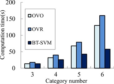
With the increase of category number, OVO-SVM, OVR-SVM and the method proposed in this paper have a certain difference in computational efficiency which includes training time and testing time. As shown in Fig. 13, OVO-SVM and BT-SVM have similar computational efficiency and both better than OVR-SVM. This is because there is partial overlap between the data of different damage category. OVR-SVM takes more time than OVO-SVM which has more number of comparing in classification comparison. But the time of classification will increase with the increasing number of comparison when the category is increasing. Time of OVO-SVM increases faster than other two methods, it can be predict that time of OVO-SVM will exceed OVR-SVM soon. Computed strength of BT-SVM is same as OVR-SVM at the first comparison, but the data involved in comparison of BT-SVM is reducing in the following comparison. The computational efficiency of BT-SVM is improved obviously. As shown in Fig. 13, the time needed grows slowest of BT-SVM in these methods.
Fig. 13Trend of computational efficiency with the change of category number
6. Experimental verification on actual aircraft structure
6.1. Experiment set-up and experiment process
As shown in Fig. 14(a), Periodic random loading was applied by English INSTRON fatigue machine. Its maximum is 73.21 kN and loading frequency is 2 Hz. Narrow band signal was generated by NI-PX15412 signal generator as excitation signal and its center frequency is 300 kHz. The signal was received by NI-PXI6115 data acquisition card.
As shown in Fig. 14(b), the experimental subject is tail reinforced frame of aircraft. In order to monitor crack propagation effectively, six PZT sensors were arranged according to the experience. No. 1 and No. 4 were used to excite signal while No. 2-6 were used to receive signal.
Fig. 14a) Experimental set-up of tail reinforced frame and b) sensors arrangement
a)
b)
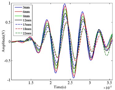
Fatigue loading experiments had been done for two experimental specimens similarly. Fig. 15 records the crack extension process with the increasing number of loading. In the experimental process, signal was collected at intervals for a certain time of rise and fall. 100 groups of data were collected of every state when the machine stopped working. Fig. 16 shows the Lamb wave signals of different crack length in specimen 1.
Fig. 15Crack extension process of reinforce frame
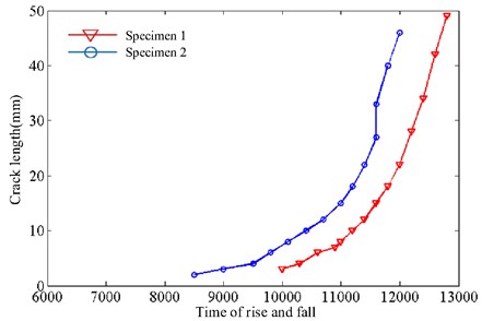
Fig. 16The Lamb wave signals of different crack length
6.2. Experimental results and analysis
Six states were chosen to analyze from the data, each set of data intercepts 200 points for analysis. Different damage states can be defined as: (1) C1 → 3 mm, (2) C2 → 6 mm, (3) C3 → 8 mm, (4) C4 → 12 mm, (5) C5 → 15 mm, (6) C6 → 18 mm.
This experiment mainly studied the crack extension process of left stress concentration area. The data of specimen 1 were used for training and the data of specimen 2 were used for testing. Similarly, the training error is 10 % and better classification effect can be obtained when kernel function parameter and penalty factor .
Table 4 shows the test result and test accuracy of every class all exceed 70 % while it is lower than the result of lug joint experiment. This may because the specimen is complex and the distance between sensors becomes longer. Table 5 illustrates that the method proposed in this paper has obvious advantage in computational efficiency.
Table 4The test result of tail reinforce frame
Identified class | |||||||
C1 | C2 | C3 | C4 | C5 | C6 | ||
Real class | C1 | 85 | 9 | 5 | 1 | 0 | 0 |
C2 | 11 | 80 | 6 | 2 | 1 | 0 | |
C3 | 7 | 10 | 78 | 4 | 1 | 0 | |
C4 | 6 | 5 | 8 | 73 | 6 | 1 | |
C5 | 4 | 2 | 4 | 8 | 75 | 7 | |
C6 | 5 | 3 | 5 | 6 | 10 | 71 | |
Table 5Computational efficiency and test accuracy of the different methods
Computation time (s) | Test accuracy | |
OVO-SVM | 126 | 77.50 % |
OVR-SVM | 157 | 78.50 % |
BT-SVM | 55 | 77.00 % |
7. Conclusions
The method combined with matching pursuit method and BT-SVM method was proposed to monitor the crack length. Also, the application of this method in the actual structure was explored in this paper.
Matching pursuit adaptive signal processing methods based on library base consisted of Chirplet atoms can extract the feature vectors which were sensitive to cracks quickly and accurately. Also, it can improve the classification effect and the efficiency of classification.
The simulation result showed that the amplitude of signal gradually decayed with the increasing crack length in the process of Lamb wave propagation. The experimental results of lug joint indicated the feasibility of this method proposed in this paper which aimed to monitor crack length on-line.
In the tail reinforce frame fatigue experiment, the method proposed in this paper was able to monitor crack length in actual aircraft structure on-line. It provides a new method for quantificational monitoring crack length in aircraft structure.
The data size of practical engineering application is usually large. Compared with traditional multi-class classification methods, BT-SVM method takes less time and computational efficiency is higher. So, it has a certain engineering application prospects.
References
-
Yu Y. H., Choi J. H., Kweon, J. H., et al. A study on the failure detection of composite materials using an acoustic emission. Composite Structures, Vol. 75, Issues 1-4, 2006, p. 163-169.
-
Genest M., Martinez M., Mrad N., et al. Pulsed thermography for non-destructive evaluation and damage growth monitoring of bonded repairs. Composite. Structures, Vol. 88, Issue 1, 2009, p. 112-120.
-
Simsir M., Ankara A. Comparison of two nondestructive inspection techniques on the basis of sensitivity and reliability. Materials Design, Vol. 28, Issue 5, 2007, p. 1433-1439.
-
Aymerich F., Meili S. Ultrasonic evaluation of matrix damage in impacted composite laminates. Composites Part B: Engineering, Vol. 31, Issue 1, 2000, p. 1-6.
-
Coelho C. K., Das S., Chattopadhyay A., et al. Detection of fatigue cracks and torque loss in bolted joints. Health Monitoring of Structural and Biological Systems, 2007, p. 653204-653212.
-
Yuan S. F., Chu F. L. Support vector machines based fault diagnosis for turbo-pump rotor. Mechanical Systems and Signal Processing, Vol. 20, Issue 4, 2006, p. 939-952.
-
Vapnik V. N. Statistical Learning Theory. Wiley-Inter-Science, New York, 1998.
-
Deng Nai Yang, Tian Ying Jie A New Method for Data Mining – Support Vector Machine. Science Press, Bei Jing, 2004.
-
Roh Yongrae, Kim Dong Young, Yang Seung Han, et al. PZT-induced lamb waves and pattern recognition for on-line health monitoring of jointed steel plates. Key Engineering Materials, Vol. 321, Issues 323-1, 2006, p. 146-151.
-
Dino I., Rajprasad R. Pipeline defect prediction using support vector machines. Applied Artificial Intelligence, Vol. 23, Issue 8, 2009, p. 758-771.
-
Liu Long, Meng Guang Study on damage diagnosis of beam-like structures by support vector regression. Journal of Vibration and Shock, Vol. 25, Issue 3, 2006, p. 99-100.
-
Krelel U. Pairwise Classification and Support Vector Machines. MIT Press, Cambridge, 1999, p. 255-268.
-
Bottou L., Cortes C., Denker J. Comparison of classifier methods: a case study in handwriting digit recognition. Proceedings of International Conference on Pattern Recognition, 1994: 77-87.
-
Ying Wei, Wang Zheng Ou, An Jin Lng Study on multiclass text categorization method based on improved support vector machine. Computer Engineering, Vol. 32, Issue 16, 2006, p. 74-76.
-
Hong J. C., Sun K. H., Kim Y. Y. The matching pursuit approach based on the modulated Gaussian pulse for efficient guided wave inspection. Smart Materials and Structures, Vol. 14, Issue 4, 2005, p. 548-560.
-
Ajay R., Carlos E. S. C. Guided-wave signal processing using chirplet matching pursuits and mode correlation for structural health monitoring. Smart Materials and Structures, Vol. 16, Issue 2, 2007, p. 355-366.
-
Zhong Chen, Xianmin Zhang Noise and vibration assessment of permanent-magnet synchronous motors based on matching pursuit. Journal of Vibroengineering, Vol. 16, Issue 4, 2014, p. 1831-1841.
-
Chattopadhyay A., Das S., Coelho C. K. Damage diagnosis using a kernel-based method. Insight-Non-Destructive Testing and Condition Monitoring, Vol. 49, Issue 8, 2007, p. 451-458.
-
Mallat S. G., Zhang Z. Matching pursuits with time-frequency dictionaries. IEEE Transactions on Signal Processing, Vol. 41, Issue 12, 1993, p. 3397-3415.
-
Qian S., Chen D. Signal representation via adaptive normalized Gaussian functions. Signal Processing, Vol. 36, 1994, p. 1-11.
About this article

This research is partially supported by the National Natural Science Foundation of China (Grant No. 51475228), the Research Fund of State Key Laboratory of Mechanics and Control of Mechanical Structures (Nanjing University of Aeronautics and Astronautics) (Grant No. 0515G01) and the Priority Academic Program Development of Jiangsu Higher Education Institutions.
